
23 minute read
Safety rules Safety rules

from New Holland RG 170.B VARIABLE POWER Motor Grader Operator's & Maintenance Manual 75314349 - PDF

SAFETY RULES
Read and follow all safety rules and decals on the machine prior to any servicing of the machine.
Do not carry rings, wrist watches, jewelry, loose clothing such as ties, torn clothes, neck scarfs, unbottoned or zippered shirts or sweaters that may get caught in rotating parts. Use of helmets, slip proof shoes, safety gloves, ear mufflers, safety goggles, etc., is recommended.
Keep all hand rails, ladders and steps clean and free from any foreign objects, oil, grease or mud to keep the chance of slipping or stumbling to a minimum.
Do not jump on or off the machine.
Always keep both hands and one foot or both feet and one hand on the ladders and grab handles. Do not use controls or hoses as a handhold: these parts are movable and do not provide a steady support; also, inadvertent movement of a control may cause inadvertent movement of the machine or the implement.
Do not operate the unit or use any implements from any position other than the seated operating position.
Under all circumstances, always keep your head, body, members, hands and feet in the driving position to keep the risk of being exposed to external hazards to a minimum.
Do not leave the machine until all movement has stopped. STARTING

Do not start or drive a damaged machine. Before using the machine ensure that any hazardous safety situation has been properly corrected. Test brakes, steering and implement controls prior to starting the machine. Advise service people of any operating malfunction.
Check, adjust or lock seat in position to provide maximum operating comfort. Prior to driving the machine or engaging any implements or attachments, ensure no one is within the machine's radius of operation. Before climbing onto the machine, take an inspection walk around the machine. Observe all signage provided by flags, posters or signs. Due to the presence of flammable fluids in the machine, do not check or fill the fuel tank and batteries adjacent to excessive heat, open flame or sparks.
OPERATION
Never operate the machine in closed spaces, unless there is an efficient system of aspiration of the exhaust gases.
Do not use the machine to transport objects, unless an appropriate arrangement for this purpose is provided.
Do not transport people on the machine, unless an appropriate arrangement has been developed specifically for this purpose.
Try to know and become familiar with all machine outlet alternatives, so you can use them in an emergency.
Do not try to get on or off the machine while it is moving.
During operation, always look in the direction of machine travel. Keep alert to the presence of people, particularly children. If anyone comes within the machine´s operating range, stop machine immediately.
Always keep a safe distance from other machines or obstacles, in order to provide minimum visibility at all times.
SAFETY RULES
STOPPING
Never abandon the machine with the engine running. Before leaving the operating area and after ensuring no persons are around the machine, slowly lower the control arms to the ground. Lock all controls and switch off the master switch.
Park the machine in an area where other machines are not operating and where there is no movement of other vehicles. Choose a firm, flat surface. If that is not possible, park the machine across the downgrade and check for any risk of sliding. Where stopping is not possible away from the traffic route, use of safety signs (flags, torches and other signage indicating danger) is recommended. These signs serve as warning to other drivers approaching the area. Never lower the implements from a position other than the operator’s position.
MAINTENANCE
GENERAL
Prior to working on or servicing the machine: 1. Read carefully all safety rules in this Manual; 2. Read and follow all safety decals and instructions attached to the machine. Do not allow non-authorized people to operate or carry out any servicing of the machine. Do not carry out any servicing without previous consent. Follow procedures provided for maintenance and servicing in this Manual.
Do not carry rings, wrist watches, jewelry, loose clothing such as ties, torn clothes, neck scarfs, unbottoned or zippered shirts or sweaters that may get caught in rotating parts. Use of helmets, slip proof shoes, safety gloves, ear mufflers, safety goggles, etc., is recommended. Keep all hand rails, ladders and steps clean and free from any foreign objects or oil spots, grease or mud to keep the chance of slipping or stumbling to a minimum.
Do not jump on or off the machine.
Always keep both hands and one foot or both feet and one hand on the ladders and grab handles. Do not carry out any servicing of the machine with people seated on the operator’s seat other an experienced and licensed operator who is assisting in the operation. If an implement must be operated during servicing or while working on the machine, ensure the operation is carried out from the seat operator’s position only.
Keep the operator’s immediate vicinity free from any loose objects at all times. Always lock the operating arms, or those machines parts that will be raised, prior to carrying out any work under these parts while they are in the raised position.
Do not allow any persons to circulate near or under the raised implement in unlocked condition. Avoid as possible standing under an attachment in the raised position, even it is locked.
Never carry out any servicing of the machine with the engine running, other than as recommended.
Where the servicing operation contemplates access to components that cannot be reached from the ground, use a ladder or raised catwalk. If neither of these is available, use any means of access available on the machine. All servicing operations shall be carried with maximum care and caution.
Do not check or refuel the fuel tank and batteries while smoking or near a naked flame or sparks as the fluid and fluid vapors are highly flammable.
If the machine must be towed, use only tiedowns provided. Engage carefully, ensuring prior to towing that required pins and locks are firmly attached in place.
When transporting a damaged machine, utilize as possible a flat, low deck trailer. If the machine must be towed, use local traffic signs and signaling. To load and unload the machine, choose a flat area that offers good ground support for the truck wheels.
Use loading ramps of sufficient height and slope. Quickly attach machine to loading deck of the truck and block the tracks or wheels with wedged chocks.
SAFETY RULES
If there is need to lift or transport heavy parts, use a hoist or similar equipment of proper capacity. Use lifting supports, if provided. Ensure there are no other persons in the vicinity.
Never use gasoline, diesel fuel or other flammable fluids such as detergents. Use authorized commercial, non-flammable, non-toxic solvents.
When using compressed air to clean parts, use sideflapped safety glasses. Keep air pressure to 2 kg/cm² maximum.
Never operate the machine in closed spaces, unless there is an efficient system of aspiration of the exhaust gases. Do not smoke, light flames or cause sparks when refueling or using readily flammable products. Do not use naked flames as a lighting means when servicing or looking for leaks. Do not pile up rags or cloth soaked up in oil, grease or flammable fluid. These are serious fire hazards. Dispose of them into closed metal containers. Prior to operating the machine or engaging any implements or attachments, check, adjust and lock the operator´s seat in position. Ensure no one is within the machine´s area of operation. Rust inhibitors usually are volatile, flammable products. These must always be used in properly ventilated environments. Containers must be kept in fresh, dry, ventilated places not accessible to nonauthorized people. Do not carry in your pockets objects that can drop into machine slots or openings. Clutches, brakes and other auxiliary equipment (distributor, cylinders, etc.) must be properly adjusted according to procedures published in the technical literature. Do not adjust with the engine running.
When carrying out any servicing of the braking system, which will likely make them temporarily inoperative, park machine on level ground and chock all wheels with proper chocks. When working under the machine or beneath raised attachments, move with caution. Wear proper safety equipment such as: safety helmet, safety goggles, anti-slip shoes and ear mufflers. Check that all tools are in good state of repair. When carrying out any checks where the engine must be kept running, use the help of an operator who must be in the operator´s seat and keep him at all times within your area of visibility. Never carry out any checks or repairs for which you have not been authorized. Follow procedures and recommendations in the technical service publications. In the event of carrying out any work outside the workshop, park machine on level ground and chock all wheels. Do not rely on flattened or doubled cables or chains. Never use them for lifting or towing. Use only proper safety gloves to handle them. The area where service operations are carried out must be kept clean and dry at all times. Immediately eliminate any impounded water or oil spills on the floor. When welding, use of safety welder's glasses, safety helmet, leather apron, gloves and safety shoes is mandatory. Safety glasses must be used as well by persons in the adjacent area, even though not participating in the work.
Never stare into the weld beam without proper eye protection.
Prior to performing any welding work on fuel tanks or adjacent to fuel tanks, drain all the contents from the tank and flush it properly to remove all residue and fumes that may have remained inside the tank.
Become thoroughly familiar with the capacity and operation of hydraulic jacks or other lifting devices.. Remember that the attaching point for lifting the machine must be appropriate to the load to be lifted and that the machine area of support on the ground must be stable.
Any loads lifted with a hydraulic jack or loads lifted with other lifting means are hazardous. Prior to lifting, transfer the weight from the hydraulic jacks to other more secure means (stands, etc.).
Wire ropes fray out with use. When handling wire ropes, wear proper protection (safety goggles, leather rasp safety gloves, etc.).
SAFETY RULES
Never use make-shift hydraulic jacks to adjust track tensions. Follow established procedures in the Repair Manual.
Handle all parts with extreme care. Keep your hands and fingers out of slots, gears and such.
STARTING Do not run engine in closed spaces without proper ventilation systems for the exhaust gases. Never expose your head, body, feet, hands and fingers close to rotating fans or belts.
ENGINE Turn radiator cap slowly to relieve system pressure, prior to removing the cap. If any coolant is needed, add only to a cold or slow running engine. Do not refuel machine with the engine running, to prevent fire.
Never attempt to check or adjust belt tensions with the engine running.
Avoid running the engine with air intakes open without the protective guards.
If for any technical reasons, this is not possible, fit proper protections over these openings prior to servicing or operating.
ELECTRICAL SYSTEM If you have to jump start, remember cable ends must be connected as follows: (+) to (+) and (-) to (-). Avoid short-circuits. Follow carefully the instructions in this Manual. Prior to any servicing of the electrical system, ensure the battery master switch is disconnected.
The fumes released by the battery are highly flammable. While recharging, leave batteries uncovered for ventilation. Never check battery charge using by short-circuiting the battery terminals. Do not smoke hear batteries to prevent explosions.
Prior to carrying out any servicing, check for fuel or battery electrolyte leaks. Eliminate these leaks prior to proceeding with the work.
Do not charge batteries in closed spaces: check for proper ventilation to prevent possible inadvertent explosion caused by fumes buildup from the charging operation.
HYDRAULIC SYSTEM Fluid gushing from a hole can be invisible to the eye but have sufficient force to penetrate the skin causing serious injuries. Under these circumstances, if you have to locate leaks, use a piece of cardboard or wood.
Never use your bare hands: if the fluid penetrates your skin, see a doctor immediately. Lack of ready medical attention may lead to serious complications and skin disease.
Relieve internal system pressure prior to removing any caps, plugs, etc. (See applicable instructions).
When checking system pressures, use appropriate measuring instruments.
IMPLEMENTS Keep your head, body, feet and hands away from the raised blade and rear attachments. Use supports provided as a safety measure, prior to proceeding to servicing and repair operations. Use proper safety equipment.
If you must operate an attachment using the hydraulic machine control system, remember this operation must be carried out only from the operator’s seat position. The operator is responsible for any nonauthorized persons allowed into the cab.
Ensure no other persons are within the machine’s radius of operation.
Give warnings with the horn or using your own voice. Lift the attachment slowly.
Do not use the machine for transporting loose objects, unless suitable means are provided for this purpose.
When leaving the operator’s cab, lower the attachment to the ground.
Prior to carrying out any servicing or repair operation with raised attachments, propely support them.
It is recommended that you carry a FIRST AID kit on the machine.
SYMBOLS
MAIN SYMBOLS USED IN THIS MANUAL
WARNING (Alert symbol)
FUELING
AIR CLEANER RESTRICTION
PARKING BRAKE
HYDRAULIC OIL FILTER RESTRICTION
TRANSMISSION OIL FILTER RESTRICTION
BATTERY
LOW BRAKE FLUID PRESSURE
COOLANT TEMPERATURE
ELECTRICAL SYSTEM
HYDRAULIC OIL TEMPERATURE
TRANSMISSION OIL TEMPERATURE LAMP
LOW TRANSMISSION HYDRAULIC OIL PRESSURE
LOW ENGINE HYDRAULIC OIL PRESSURE
DIFFERENTIAL LOCK
HOURMETER
OPERATOR´S SEAT ADJUSTMENT
LOCKED
UNLOCKED
BLADE FLOAT (RH cylinder)
BLADE FLOAT (LH cylinder)
FRONT BLADE FLOAT
RIPPER
SCARIFIER
GENERAL SIGNALLING SADDLE LOCK
EMERGENCY STEERING AUDIBLE SIGNAL
SYMBOLS
MAIN SYMBOLS USED IN THIS MANUAL
RIGHT HAND TURN SIGNAL
LEFT HAND TURN SIGNAL
LOW ENGINE RPM
HIGH ENGINE RPM
FRONT WIER (OPTION)
FRONT WIPER/WASHER, LOWER LH AND RH (OPTION)
FRONT WINDSCREEN WASHER (OPTION)
FAN/HEATER (OPTION)
DEFROSTER
REAR WORK LAMP
CAB LIGHT
BLAD WORKING LAMP
REAR WIPER/WASHER (OPTION)
STROBE LIGHT (OPTIONAL) ROAD LIGHTS/LOW BEAM AND CLUSTER LIGHTS
HIGH BEAM
BLAD ANTI-SHOCK SYSTEM
COLD STARTING AID (OPTION)
WARNING (Pressurized fluid)
WARNING (Poisenous gases)
WARNING (Electrical shock)
WARNING (Tire pressure)
WARNING (Blood contamination)
WARNING (Hot radiator)
DANGER (Your life is involved)
ARTICULATION
ADVERTÊNCIA WARNING
AVOID INJURIES EVITE OS ACIDENTES NÃO SALTE DO NOT JUMP IF MACHINE
SE A MÁQUINA CAPOTAR OVERTURNS
USE O CINTO DE FASTEN SEGURANÇA SEAT BELT SWITCHING OFF
SWITCH OFF AND REMOVE
MASTER BATTERY SWITCH AT
THE END OF OPERA-TION OR
PRIOR TO TRANSPORTING
MACHINE
(1*)
WARNING
ENGINE STARTING INSTRUCTIONS
TURN KEY UNTIL ENGINE STARTS. IF ENGINE DOES NOT START WITHIN 30 SECONDS, STOP AND WAIT 2 MINUTES UNTIL THE STARTER MOTOR COOLS DOWN BEFORE THE NEXT ATTEMPT.
ENGINE COLD
START ENGINE WITH HAND THROTTLE AT MINIMUM OR ONE QUARTER OPEN. INCREASE ENGINE SPEED TO MIDWAY TRAVEL OF THE THROTTLE LEVER AND WAIT UNTIL COOLANT TEMPERATURE GAUGE NEEDLE MOVES OUT OF MINIMUM POSITION. RUN ENGINE AT HALF SPEED UNTIL NORMAL OPERATING TEMPERATURE IS REACHED.
ENGINE WARM
START ENGINE WITH HAND THROTTLE APPROXIMATELY AT ONE QUARTER TRAVEL.
SWITCHING OFF THE ENGINE
RUN ENGINE FOR 3 TO 4 MINUTES BEFORE SWITCHING OFF.
WARNING
12 VOLTS
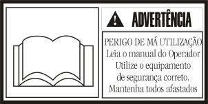
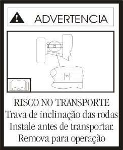
WARNING

POOR USAGE HAZARD Read Operator´s Manual Use proper safety gear Keep all people away TRANSPORT HAZARD Wheel angle lock Install for transport Remove for operation
(1*: Instructions decals for Operation / page18)
DESLIGAR WARNING
Mantenha distancia ou KEEP AWAY desligue o motor antes de efetuar a manutenção Switch off engine prior to servicing
ADVERTÊNCIA WARNING
PERIGO NOS DANGER PONTOS DE MORDEDURA BITE POINTS
Mantenha-se Keep away afastado WARNING
• Lea el Manual del Operador
• Ajujste el cinturón de seguridad
• No lleve pasajeros
• Aleje a la gente de la máquina WARNING ADVERTÊNCIA WARNING
RISCO DE CRUSHING HAZARD ESMAGAMENTO Use safety lock prior
Engate a trava de to servicing or segurança antes de transporting the fazer a manutenção ou transportar a máquina machine SWITCH ENGINE OFF SWITCH ENGINE OFF AND REMOVE MASTER BATTERY SWITCH AT THE END OF OPERA-TION OR PRIOR TO TRANSPORTING MACHINE
WARNING ADVERTÊNCIA WARNING
CRUSHING HAZARD Keep away
PERIGO NOS DANGER PONTOS DE MORDEDURA BITE POINTS Mantenha-se Keep away afastado ADVERTÊNCIA WARNING
PERIGO NOS DANGER PONTOS DE MORDEDURA BITE POINTS Mantenha-se Keep away afastado
EMERGÊNCIA PARA TRANSMISSÃO EM CASO DE FALHA NA CENTRAL ELETRÔNICA (ECU) SEGUIR AS INSTRUÇÕES DESCRITAS
1- DESCONECTAR OS CONECTORES CINZAS NÚMEROS 1 E 2
. 2- DESCONECTAR OS CONECTORES 3 E 4;.
3- CONECTAR NÚMEROS 2 E 3.
4- LER O MANUAL DO OPERADOR PARA DEMAIS INSTRUÇÕES.
5- ANTES DE ACIONAR A MÁQUINA CERTIFICAR-SE QUE NÃO EXISTEM PESSOAS PRÓXIMAS DA MÁQUINA.
6- MOVER A MÁQUINA EM CURTA DISTÂNCIA PARA UM LUGAR AONDE O SERVIÇO POSSA SER FEITO.
PERIGO DANGER
PERIGO DE RUN OVER ATROPELAMENTO HAZARD Mantenha distancia Keep away from da máquina machine
ADVERTÊNCIA WARNING
PERIGO DECORRENTE DANGER FROM HOT DE SISTEMA PRESSURIZED PRESSURIZADO SYSTEM Alivie a pressão antes Relieve pressure de fazer manutenção prior to servicing DANGER
DANGER OF GETTING CAUGHT Keep away or switch off engine prior to servicing
FG 140.2
ADVERTÊNCIA WARNING
PERIGO DECORRENTE DE LÍQUIDO QUENTE DANGER FROM HOT SOB PRESSÃO PRESSURIZED FLUID Preste serviço de Service when cold manutenção quando estiver frio.
ADVERTÊNCIA WARNING
PERIGO DECORRENTE DE LÍQUIDO QUENTE DANGER FROM HOT SOB PRESSÃO Preste serviço de PRESSURIZED FLUID manutenção quando Service when cold estiver frio.
PERIGO DANGER
Dê partida no motor Start engine from the do assento do operador operator´s seat position. transmissão em neutro Transmission in neutral
Skidproof
ENGINE STARTING INSTRUCTIONS TURN KEY UNTIL ENGINE STARTS. IF ENGINE DOES NOT START WITHIN 30 SECONDS, STOP AND WAIT 2 MINUTES UNTIL THE STARTER MOTOR COOLS DOWN BEFORE THE NEXT ATTEMPT.
ENGINE COLD
START ENGINE WITH HAND THROTTLE AT MINIMUM OR ONE QUARTER OPEN. INCREASE ENGINE SPEED TO MIDWAY TRAVEL OF THE THROTTLE LEVER AND WAIT UNTIL COOLANT TEMPERATURE GAUGE NEEDLE MOVES OUT OF MINIMUM POSITION. RUN ENGINE AT HALF SPEED UNTIL NORMAL OPERATING TEMPERATURE IS REACHED.
ENGINE WARM
START ENGINE WITH HAND THROTTLE APPROXIMATELY AT ONE QUARTER TRAVEL.
SWITCHING OFF THE ENGINE
RUN ENGINE FOR 3 TO 4 MINUTES BEFORE SWITCHING OFF.
PERIGO DANGER
Dê partida no motor Start engine from the do assento do operador operator´s seat position. transmissão em neutro Transmission in neutral
PERIGO DANGER
RUN OVER PERIGO DE ATROPELAMENTO HAZARD Mantenha distancia Keep away from da máquina machine
SWITCHING OFF
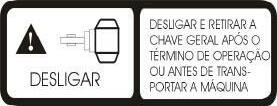
SWITCH OFF AND REMOVE MASTER BATTERY SWITCH AT THE END OF OPERATION OR PRIOR TO TRANSPORTING MACHINE
ADVERTÊNCIA WARNING
PERIGO DECORRENTE DE LÍQUIDO QUENTE DANGER FROM SOB PRESSÃO HOT PRESSURIZED
Preste serviço de FLUID manutenção quando estiver frio. Service when cold

WARNING
REMOVE WHEEL ANGLE ANCHOR PIN PRIOR TO OPERATING MACHINE
ADVERTÊNCIA WARNING
PERIGO DECORRENTE DE LÍQUIDO QUENTE DANGER FROM SOB PRESSÃO Preste serviço de HOT PRESSURIZED FLUID manutenção quando Service when cold estiver frio.
WARNING
POOR USAGE HAZARD Read Operator´s Manual Use proper safety gear Keep all people away DESLIGAR SWITCH OFF ENGINE
Mantenha distancia ou Keep away or desligue o motor antes switch off engine de efetuar a manutenção prior to servicing
ADVERTÊNCIA WARNING
PERIGO DECORRENTE DE SISTEMA PRESSURIZADO Alivie a pressão antes DANGER FROM HOT PRESSURIZED SYSTEM Relieve pressure prior to de fazer manutenção servicing
ADVERTÊNCIA WARNING
PERIGO NOS BITE POINTS PONTOS DE MORDEDURA HAZARD Mantenha-se Keep away afastado
ADVERTÊNCIA WARNING
RISCO DE ESMAGAMENTO Engate a trava de CRUSHING HAZARD Engage safety lock prior to segurança antes de servicing or transporting fazer a manutenção ou the machine transportar a máquina
WARNING
INSTRUÇÕES DE OPERAÇÃO INSTRUÇÕES DE OPERAÇÃO // QUICK OPERATION INSTRUCTIONS QUICK OPERATION INSTRUCTIONS Chave de Ignição (Key switch) Chave de Ignição (Key switch) Chave geral (Master switch) Chave geral (Master switch)
Dar partida no motor: Dar partida no motor: a)Alavanca de marcha em neutro e acelerador em marcha lenta. b)Ligar a chave geral. c)Dar partida na chave de ignição.
Engine starting Engine starting a)Gear selector lever in neutral position and throttle lever at low position. b)Turn on master switch. c)Turn on key switch.
Alavanca de marchas (Gear selector lever): Alavanca de marchas (Gear selector lever):
Movimentar a máquina: Movimentar a máquina: a)Acionar o pedal da embreagem. b)Soltar o freio de mão. c)Levantar a trava da alavanca de marchas e movimentar a alavanca para frente ou para trás. d)Soltar o pedal da embreagem lentamente.
To move the machine: To move the machine: a)Press inching pedal. b)Release parking brake lever. c)Lift gear selector lever lock and move the lever to forward or reverse. d)Release inching pedal slowly.
Pedal da Embreagem (Inching Control Pedal) Pedal da Embreagem (Inching Control Pedal)
Alav. de inclinação das rodas e articulação do chassis: Alav. de inclinação das rodas e articulação do chassis: (Wheel lean control lever and frame articulation lever) (Wheel lean control lever and frame articulation lever) Atenção: Atenção: Não acionar a alavanca de inclinação das rodas com o parafuso trava montado na barra de inclinação e também a alavanca de articulação chassis com o pino de travamento montado nos chassis. Warning: Warning: Do not move the wheel lean lever with lock bolt locked and do not move the articulation frame lever with the lock pin locked on frames.
Parafuso Trava – Eixo Dianteiro Parafuso Trava – Eixo Dianteiro (Lock Bolt – Front Axle) (Lock Bolt – Front Axle)
Alavanca de Controle da Lâmina: Alavanca de Controle da Lâmina: (Blade Control Lever) (Blade Control Lever) Atenção: Atenção: Cuidado ao deslocar a lâmina para não danificar a escada / pneus.
Warning: Warning: Be careful when moving the moldboard to avoid step / tires damage.
Alavancas de controle da lâmina Alavancas de controle da lâmina (Blade control levers) (Blade control levers)
Pino travamento chassis Pino travamento chassis (Frames lock pi (Frames lock pi n) n)
RG 170.B
MOTORGRADER MOTORGRADER V VARIABLE POWER ARIABLE POWER
THE SAFETY OF THE OPERATOR AND THAT OF THE PEOPLE IN HIS IMMEDIATE VICINITY, DEPENDS ON CAUTION WHEN USING THE MACHINE. THEREFORE, THE OPERATOR MUST KNOW THE LOCATION AND FUNCTION OF EACH CONTROL. EACH MACHINE HAS ITS OWN LIMITATIONS. PRIOR TO OPERATING, THE OPERATOR MUST BE THOROUGHLY FAMILIAR WITH THE MACHINE´S CAPABILITIES AND PERFORMANCE OF THE BRAKING, STEERING AND STABILITY SYSTEMS.
IDENTIFICATION PLATES RG 170.B
1 -MANUFACTURER´S IDENTIFICATION
PLATE 3 - MARKING ON REAR FRAME RIGHT HAND SIDE - DIRECTION OF FORWARD TRAVEL
New Holland Construction
Model Number
CNH America LLC Racine, W53404 U.S.A. Made in Brazil
Produtc Identification Number
0 1 2 3 4 5 6 7 8 9
NUMBER USED ( SCALE 1:1 )
CUMMINS ENGINE ID PLATE

TECHNICAL DATA
ENGINE
Model ...................................... Cummins QSB 5.9 Diesel, 4 stroke,direct injection, turbocharged and emissions compliant. No. of cylinders ............................................6 (six) Displacement ........................................ 5.880 cm3 Bore and stroke: .............................. 102 x 120 mm
Power: (SAE J 1995) Gear 1 st to 3 rd forward 1st to 2 rd rearward Gross ........................ 183 HP(136 kW) @ 2200 rpm Net............................ 170 HP(126 kW) @ 2200 rpm Torque, max. (net) .................. 862 Nm @ 1500 rpm
TRANSMISSION
Type ................................................... Direct drive, by countershaft, power shift, with electronic gear change control and inching pedal.
Pump flow at 2.200 rpm ............................91 l/min Oil sump .................................................... integral Gears ................................8 forward and 4 reverse Ground speed control .......... Electronic auto control, "bump" type single lever Diagnosis system .....................................on board Speeds - km/h(mph) Forward 1st ........................................... 3,6(2,2) 2nd........................................... 5,1(3,2) 3rd ........................................... 7,2(4,4) 4th ........................................... 10,0(6,2) 5th ........................................... 14,3(8,9) 6th ........................................... 20,0(12,4) 7th ........................................... 28,5(17,7) 8th ........................................... 42,9(26,6)
Reverse 1st ........................................... 3,6(2,2) 2nd........................................... 7,2(4,4) 3rd ........................................... 14,3(8,9) 4th ........................................... 28,5(17,7)
STEERING Front wheels: Type ................................................servo assisted Wheel turn angle .................. 48o to the left or right Steering cylinders ....................................... 2 (two) Bore and stroke ........................... 63,2 x 266,7 mm Articulated frame: Hydraulically controlled articulation Articulation angle (RH and LH) .......................... 250 Cylinders .................................................... 2 (two) Bore and stroke ................................ 80 x 377 mm Turning radius, min. .................. 7.250 mm (23,7 ft)
TIRES
13.00 X 24 - 12 PR ............. STANDARD 14,00 X 24 - 10 PR ............. OPTIONAL 14,00 X 24 - 12 PR ............. OPTIONAL 17,50 X 25 - 12 PR ............. OPTIONAL
FLUID CAPACITIES (LITRES)
Fuel tank ................................................... 340,0 l Coolant ................................................................ Total....................................... 10.5 US gal (40,0 l) Crankcase (with filter).............. 4.3 US gal (16,4 l ) Transmission ............................ 6.6 US gal (25,0 l) Tandem(each)(DANA axle) ...... 5.9 US gal (22,7 l) Tandem(each)(Graziano axle) ........7 US gal (29,0 l Hydraulic system and reservoir 5.9 US gal (180,0 l) Rear axle (STD Graziano) .............7 US gal (29,0 l) Rear axle (DANA OPT) ............. 3.2 US gal (12,0 l) Circle swing reduction ............... 0.7 US gal (2,8 l)
ELECTRICAL SYSTEM
Voltage .................................................... 24 volts Battery rating ...................................... (20h)100Ah Alternator ...................................................... 45A Number of batteries ........................................... 2
BRAKES
Service: Multiple wet disc, self-adjusting, hydraulically engaged, two independent circuits for each axle side. Safety: Service brake supply by two nitrogene accumulatores, one for each circuit, automatically engaged in the event of a system pressure drop.
Parking: Mechanical, disc type acting through the transmission.
TANDEM COMPARTMENT
Rectangular section, welded, using 19.0 (0.7 in) mm and 16.0 mm thick plates. Interchangeable shafts and gears, assembled on taper bearings. Chain pitch .................................. 50,8 mm (2 in) Tandem oscillation either way ....................... 200
TECHNICAL DATA
FRONT AXLE
Housing built from high strength steel weldment, with 190 oscillation up or down. Lateral wheel angle of 170 30' to the right or to the left, hydraulically actuated. Ground clearance .................................... 640 mm
REAR AXLE ( GRAZIANO - STD )
Cast iron housing for severy applications. Axle built from heat treated seteel, mounted on taper bearings. Ground clearance: 370 mm(15,67") Differential: Super Max Trac
REAR AXLE ( DANA - OPC )
Cast iron housing for severy applications. Axle built from heat treated seteel, mounted on taper bearings. Ground clearance: 398 mm(15,67")
OPERATING WEIGHTS
With all fluids, including radiator coolant, hydraulic oil, full fuel tank and operator´s weight.
Over front axle ...................... 9874 lbs (4.470 Kg) Over rear axle.................... 24413 lbs (10.620 Kg) Total.................................. 33267 lbs (15.090 Kg)
Machine similar its predecessor, fitted with ROPS cab, side shift and blade tilt, rear tow hook and front ripper.
Over front axle .................. 11089 lbs ( 5.030 Kg) Over rear axle.................... 23501 lbs (10.660 Kg) Total.................................. 34590 lbs (15.690 Kg)
DRAW BAR
Built from welded "A" shaped box section, with circle swing hydraulic motor mounted at the center. Connection by means of a ball joint adjusted with spacers.
FRAME
Built from welded box section. Front: Section ......................................... 254 x 298 mm Weight per lineal meter ........................... 153 Kg/m Rear (each end) : Section ............................................ 121 x 298 mm Weight per lineal meter ............................. 75 kg/m
CIRCLE
Built from one-piece steel forging, "T" cross section .......... 177 x168 x 38mm. Outside diameter ................................... 1.753 mm Turning angle .................................3600 continuous Supported on 4 guides with interchangeable phenolic resin inserts. Guide contact area ................................ 2.845 cm2 Oil bath circle swing gears.
BLADE
Build from one-piece hot stamped carbon steel. Unique "Roll Away" surround profile. Replaceable bits and cutting edge. Hydraulic controls for side shift and blade tilt.
Sizes available (12ft) 3,658x622x22mm ............................ standard (13ft) 3,960x671x22mm ................................option (14ft) 4.267x671x22mm ................................option
Maximum raise height from ground .......... 435 mm Maximum slope angle to either side ................. 900 Hydraulically adjustable blade pitch ......400 forward 50 roll-back
BLADE REACH (MEASURED OUTSIDE TIRES), NON-ARTICULATED FRAME
With circle displacement only Right side ..................................... 33 in (847 mm) Left side ......................................32.8 in (834 mm)
With blade displacement only Right side .....................................48 in (1221 mm) Left side .......................................45 in (1145 mm)
With circle and blade displacement Right side .................................. 58.8 in (1494 mm) Left side .................................... 55.3 in (1405 mm)
With circle, blade displacement and saddle rotatated in hole number one Right side .................................. 71.5 in (1817 mm) Left side ..................................... 60.5 in (60.5 mm)