1 minute read
CARE TO BE TAKEN PRIOR TO PERFORMING ANY WELDING PROCEDURE ON THE MACHINE


ELECTRICAL SYSTEM
CARE TO BE TAKEN PRIOR TO PERFORMING ANY WELDING PROCEDURE ON THE MACHINE
Disconnect the positive (+) and negative (-) cables from batteries prior to performing any welding service on the machine. Connect the welding equipment ground cable to a 0,6 m (2 feet) maximum distance from the area being welded. Do not connect the welding equipment ground cable to the module cooling plate or to the engine control module (ECM) itself. Welding work is not recommended on installed engine or components.
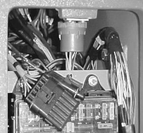
Engine Control Module (ECM) Connectors Transmission Control Module (TCM) Connectors
X23
B
A
C
ENGINE CONTROL MODULE (ECM) DETAILS, SHOWING LOCATION OF CONNECTORS A, B, AND C TO BE DISCONNECTED X24
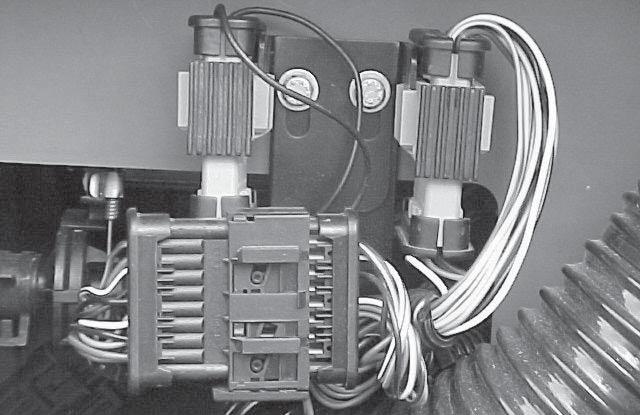
TRANSMISSION CONTROL MODULE (TCM) X24 BLACK CONNECTOR AND X23 GRAY CONNECTOR
When welding service is necessary to be performed on the machine, make sure to disconnect the X24 connector and the X23 connector from the right handside of the operator’s cab.
CAUTION: If welding service is performed without disconnecting the X24 and X23 connectors shown in illustration, damages can be caused to the transmission control module (TCM).
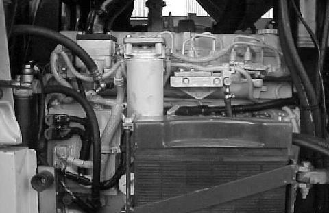
POSITION OF THE ENGINE CONTROL MODULE (ECM), ON LEFT HAND-SIDE OF THE MACHINE, IN ENGINE COMPARTMENT.
ELECTRICAL SYSTEM
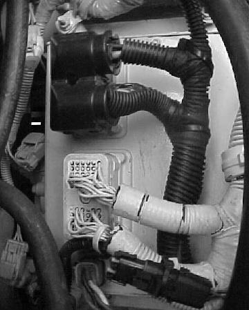
J6
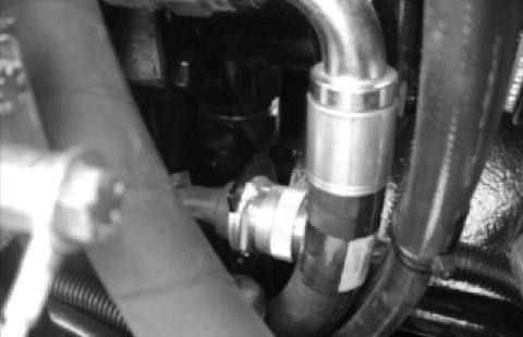
Prior to perform any welding service on the machine, disconnect J6 connector on left hand-side of the machine, next to the transmission.
J4
When welding service is necessary to be performed on the machine, make sure to disconnect the transmission control lever J4 connector, located on the right hand-side console, above the fuse block.