9 minute read
Workingwiththemachine


Generalsafetyinstructions
•Never drive up to the edge of a pit from the outside – risk of cave-in.
•Never undermine the foundations of walls – risk of collapse.
•When excavating, look out for high-voltage and underground cables, and gas and water pipes.
•When using lifting gear such as pallet forks, comply with the load diagrams –see Load diagram on page71.
•The hydraulic system of the machine is still pressurized even when the engine is not running. Depressurize the sections of the system and hydraulic lines that you want to open before starting setup or repair work (e.g., fitting/removing an attachment with hydraulic functions) –see Depressurizing the quick couplers on the telescopic unit on page78
•If your machine is equipped with a load stabilizer:
IMPORTANT!
Turn off the load stabilizer before working with the telescopic unit. If you leave the load stabilizer on, the lifting capacity of the telescopic unit is only about 60% of the rated force, and it is difficult to complete precise lifting movements.
Loaddiagram
Follow the load diagram when using pallet forks with fork arms on the telescopic unit. The telescopic unit with fork arms moves within the shaded range. The load diagram states the rated operating load on the fork arms. The maximum load varies according to the horizontal distance of the load center to the front edge of the tires.

The diagram is divided into four shaded sections to show the movement of the telescopic unit. The distance between the center of the load and the rear side of the fork arms is 24” (610mm).
Example:
•Off-road applications ➝ safety factor S=2.0
➥ Load distance to rear side of fork arms = 24” (610 mm).
•Height of fork arm above tire contact area = 4’9” (1.50 m).
•Distance to front edge of tires = 9’2” (2.80 m) (range B).
•Maximum load is 1997 lbs. (906 kg).
IMPORTANT!
The load diagram in the cab is valid only for use with the pallet forks with fork arms as specified –see Fields of application, attachments on page9. Follow the specific load diagrams of other attachments used.
Safeloadindicator
DANGER!
The safe load indicator has been set for industrial applications (S=1.25). Do not rely on the safe load indicator when working off-road –Accidentrisk.
☞ Adapt your drive speed and loads to the terrain. Refer to the load diagram for the maximum authorized loads.
A defective safe load indicator or working at more than 100% of the safe work load may cause the machine to tilt –Accidentrisk.
☞ Check the safe load indicator daily.
☞ A flashing indicator and acoustic signal warn of loads exceeding 100%. Reduce the load to below 100% by retracting the telescopic unit.
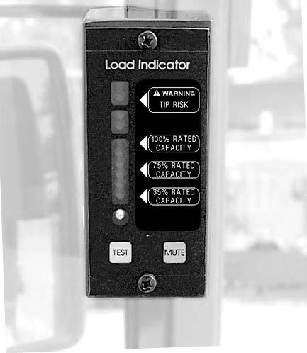
The telescopic loader is equipped with an el ectronic load indicator that continuously monitors weight changes on the rear axle during operation.
Visible and acoustic signals warn the operator of critical loads on the telescopic unit that may cause the machine to tilt forward.
IMPORTANT!
Critical side loads are not monitored, i.e., the operator is not warned of critical side loads.
The LEDS a, b and c indicate the percent of the load on the telescopic unit that is the safe work load: a Six green LEDS – indicates loads between 35 and 100% of the safe work load. b Two yellow LEDS – indicates loads over 100% of the safe work load. c Two red LEDs – indicates loads up to 122% of the safe work load. d Green LED to signal readiness. e Tip switch for checking the system. f Mute switch for adjusting the volume of the acoustic signal.
Controlvalveofthetelescopicunit:overview
Controlleverforlift,tiltand telescopiccylinders
WARNING!
Unintentional operation of the control lever (joystick) when driving on public roads –
Accidentrisk.
☞ Lock the lock lever 39/16 –see Control lever lock (joystick) on page47.
PositionLever10Function
A ☞ To the left ➥ Tilts in attachment
B ☞ To the right ➥ Dumps out attachment
C ☞ Forward ➥ Lowers telescopic unit
D ☞ Rearward ➥ Raises telescopic unit
E ☞ Fully forward ➥ Lowers telescopic unit to float position
NOTE:
The control valve is equipped with a float position. This helps you when working with a rotary broom, snowplow, and grading in reverse.
Complete the following procedures to turn on the float position:
☞ Push control lever 10 fully forward to final position E
➥ Control lever stays in final position E
Lockingthe3rdcontrolcircuit
WARNING!
When working with attachments without a hydraulic function, press tip switch 72 on control lever 10 to unlock the quickhitch facility –
Riskofpersonalinjury.
☞ Turn on rocker switch 54
☞ The 3rd control circuit is locked via rocker switch 54 (on the right on the instrument panel) as follows:
Lockingthe3rdcontrolcircuitFunction
☞ Push lock C down.
☞ At the same time press rocker switch 54 down to position B
☞ Press rocker switch 54 down to position A.
➥ Indicator 62 on the instrument panel comes on.
➥ Tip switches 72 and 73 are operational.
➥ Indicator 62 on the instrument panel turns off.
➥ Rocker switch 54 is locked.
➥ Tip switches 72 and 73 are not operational.
Locking/unlockingthequickhitch facility
NOTE:
The attachment on the quickhitch facility is locked by using toggle switch 35 “Quickhitch lock” on the instrument panel. The lock cylinder can only be locked if:
•You press tip switch 72 on control lever 10 (joystick) and toggle switch 35 on the instrument panel at the same time.
You only have to press tip switch 73 on control lever 10 (joystick) to lock the lock cylinder.
Operationof3rdcontrolcircuit
☞ The 3rd control circuit is activated by pressing tip switches 72 and 73 on the control lever 10 (rocker switch 54 turned off):
OperationFunction
Unlocking attachments without hydraulic function:
☞ Press tip switch 72 and toggle switch 35 at the same time.
Unlocking attachments with hydraulic function:
☞ Press tip switch 72
Locking:
☞ Press tip switch 73.
➥ Quickhitch facility is unlocked.
➥ Pressurizes the right-hand side blue hydraulic line.
➥ Attachment without hydraulic function:
•Locks the quickhitch facility.
➥ Attachment with hydraulic function:
•Pressurizes the left-hand side red hydraulic line.
➥ With an attachment fitted, hydraulic movements/procedures over a longer period of time or operation of hydraulic motors (e.g., rotary broom) or
Continuoussetting:
☞ Press rocker switch 79 down.
➥ Operation of hydraulic equipment with a control valve adjusted to maximum oil flow, with an unpressurized reflux.
•Indicator in rocker switch 79 comes on.
•Indicator (fig. 76/62) on the instrument panel comes on.
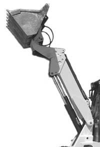
Workingwiththetelescopicunit
Raising/extendingthetelescopicunit
☞ Raise the retracted telescopic unit to the required height. To do this:
☞ Pull control lever 10/D rearward.
☞ Extend telescopic unit. To do this:
☞ Press tip switch 74 until the telescopic unit is extended to the required length.
Retracting/loweringthetelescopic unit
WARNING!
The safeworkload can be exceeded if the telescopic unit is lowered while it is extended. This can cause the machine to tilt –
Accidentrisk.
☞ Always retract the telescopic unit before you lower it.
☞ Retract the telescopic unit. To do this:
☞ Press tip switch 75 until the telescopic unit is completely retracted.
Loweringthetelescopicunitwiththe engineturnedoff
☞ Lower the retracted telescopic unit. To do this:
☞ Push lever 10/C forward.
Lower the telescopic unit as follows:
☞ Make sure no one is near the work area of the machine.
☞ Push and hold control lever 10 forward C
➥ Until the telescopic unit is completely lowered.
☞ Return control lever 10 to neutral.
Depressurizingthequickcouplerson thetelescopicunit
IMPORTANT!
The hydraulic system of the machine is still pressurized even when the engine is not running. The hydraulic quick couplers can be released, however they cannot be re-attached because the hydraulic lines are not depressurized. Therefore:
☞ Depressurize sections of the system and hydraulic lines that you plan to open before starting setup or repair work, e.g., fitting/removing an attachment.
Depressurize as follows:
☞ Apply the parking brake
➥ –see Parking brake on page50.
☞ Unlock the 3rd control circuit
➥ –see Locking the 3rd control circuit on page74.
☞ Turn off the engine
➥ Do not turn off the ignition.
☞ Press tip switches 72 and 73 on the control lever between 5 – 8 seconds.
➥ Hydraulic lines are depressurized.
☞ Turn off the ignition and remove the ignition key.
Re-installingattachments
Re-installing attachments is described below for the standard bucket. If you are fitting or removing attachments with their own hydraulic functions (e.g. high-tilt or side dump bucket), you must follow the information provided in the Operator’s Manual of the attachment.
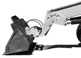
Fittingattachmentsontothequickhitchfacility
WARNING!
The attachment must always be safely locked onto the quickhitch facility –Accidentrisk.
☞ Before working, be sure that the attachment is safely locked onto the quickhitch by using the lock cylinder. Be sure that you can see the lock pins on both sides of the mounting holes on the attachment.
Re-install as follows:
☞ Drive the machine up to the attachment.
☞ Lower telescopic unit E. To do this: Push control lever 10 forward C
☞ Tilt the quickhitch facility forward. To do this: Push control lever 10 to the right B
☞ Adjust the height of pin shanks G of the quickhitch facility so that they are under catch hooks F of the attachment.
☞ Drive the machine forward until pin shanks G of the quickhitch facility are directly beneath catch hooks F of the attachment.
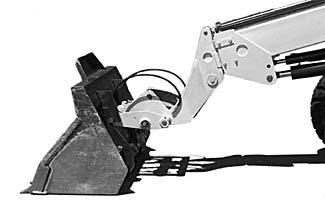
☞ Raise telescopic unit E until pin shanks G engage in catch hooks F. To do this: Pull control lever 10 rearward D
☞ Fully tilt in the quickhitch facility. To do this: Push control lever 10 to the left A.
Locking:Attachmentswithout hydraulicfunction
Secure the attachment with lock pin H of the quickhitch facility. To do this:
☞ Press tip switch 73 on the control lever.
➥ Lock pin H engages in the mounting holes of the attachment.

➥ Make sure the attachment is safely locked with lock pins H
☞ Lock the 3rd control circuit with rocker switch (fig. 76/54)
➥ –see Locking the 3rd control circuit on page74.
☞ Lock the quickhitch facility (fig. 77/35)
➥ –see Locking/unlocking the quickhitch facility on page74.
WARNING!
You must be able to see lock pins G on the left and right of the mounting holes on the attachment. The attachment is not safely locked unless you can see the lock pins.
Locking:Attachmentswithhydraulic function
☞ Turn off the engine.
➥ Do not turn off the ignition.
☞ Apply the parking brake.
☞ Unlock the 3rd control circuit.
➥ –see Locking the 3rd control circuit on page74.
☞ Depressurize the 3rd control circuit.
➥ –see Depressurizing the quick couplers on the telescopic unit on page78.
☞ Attach the hydraulic, and if used, electrical connections for the attachment in accordance with its Operator’s Manual.
Connectionofelectricallyoperated attachments(option)
The machine can be equipped with a 4-pole front socket. Rocker switch 51 on the left side of the instrument panel switches electric power supply on or off for electrically operated attachments such as a spray water pump for a rotary broom.
Powersupplyforfrontattachments(option)
☞ Press rocker switch 51 down to position B
☞ Press rocker switch 51 down to position A
➥ Power supply at the front socket is turned on.
➥ Indicator in switch comes on.
➥ Power supply is interrupted.
➥ Indicator turns off.
Removinganattachmentfromthe quickhitchfacility
WARNING!
The attachment must be placed on the ground so that it will not fall over when removed –
Riskofpersonalinjury.
☞ Position the attachment so that after unlocking it will not tip over.
Take the attachment off the quickhitch facility as follows:
☞ Drive the machine, with the attachment empty and up, to the drop-off position.
☞ Tilt in the quickhitch facility by pushing control lever 10 to the left A.
☞ Lower the telescopic unit until the attachment is about 2–4” (5–10cm) above the ground by pushing control lever 10 forward C.
☞ Unlock the 3rd control circuit with rocker switch (fig. 30/54): –see Locking the 3rd control circuit on page74.
Forattachmentswithhydraulicfunction
☞ Turn off the engine.
➥ Do not turn off the ignition.
☞ Apply the parking brake.
☞ Unlock the 3rd control circuit with the rocker switch: –see Locking the 3rd control circuit on page74.
☞ Depressurize the quick couplers: –see Depressurizing the quick couplers on the telescopic unit on page78.
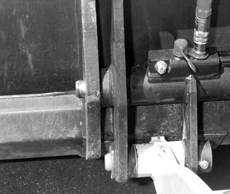
☞ Hydraulic connection for the quick couplers on the lock cylinder:
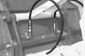
•Connect flexible line A onto plug D of the quickhitch facility.
•Connect flexible line B onto plug C of the quickhitch facility.
•Remove electrical connections if necessary.
☞ Start the engine.
☞ Release the quickhitch facility lock on the toggle switch (fig. 76/35)
➥ –see Locking/unlocking the quickhitch facility on page74
☞ Press tip switch 72 on control lever 10
☞ Slightly tilt the quickhitch facility forward by pushing control lever 10 to the right B
☞ Lower the telescopic unit. To do this:
➥ Push control lever 10 forward C
As soon as the pin shanks of quickhitch facility F are beneath the catch hooks of attachment E:
☞ Release the parking brake.
☞ Reverse the machine away from the attachment.
High-flowcontrolcircuit(option)
WARNING!
When working with attachments: Pressing tip switch 72 on the control lever (joystick) unlocks the quickhitch facility –
Riskofpersonalinjury.
☞ Lock the 3rd control circuit with rocker switch 54 on the instrument panel –see Locking the 3rd control circuit on page74.
The machine can be fitted with a high-flow control circuit (option) for operation of hydraulically operated front attachments.
Operation:
Rocker switch 78 on the control lever base console electrically locks and unlocks the highflow control circuit via a solenoid valve.
Operationofhighflowcontrolcircuit(option)
ON
OFF
☞ Press rocker switch 78 down to position B.
☞ Press rocker switch 78 down to position A
➥ High-flow control circuit is turned on.
➥ Indicator comes on.
➥ High-flow control circuit is turned off.
➥ Indicator turns off.