11 minute read
Hydraulics


Issue: (Pilot) System pressure drop
Solution: Return line with non-return valve
Possible problem:
The pilot system pressure drops during low engine idle. This is caused by low pressure in the hydraulic system -- minimum 145 – 174 psi (10 – 12 bar). The hydraulic functions do not react, or react with little control.
Measures to do:
An additional non-return valve was added to the return line, increasing hydraulic system pressure.
Id.No.: 918173
Edition: Sept. 05
Hydraulics
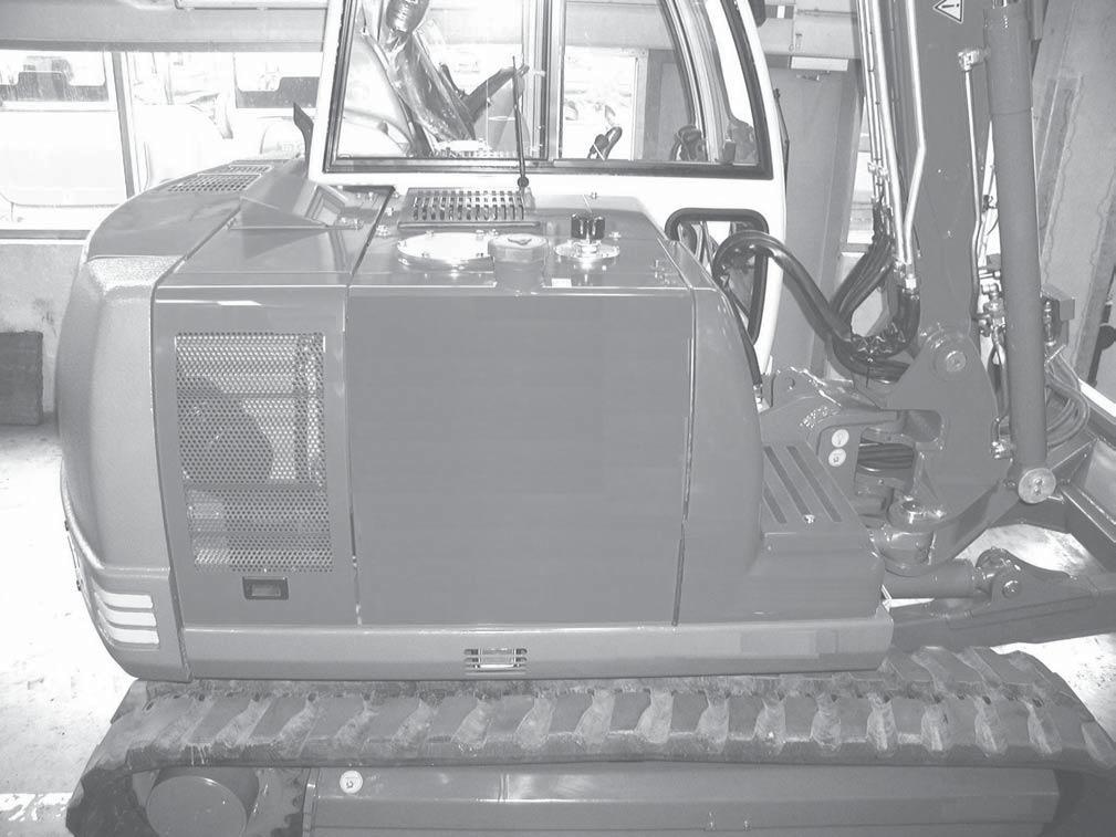
2. POSITION OF COMPONENTS
Pict.: View - right
Service cover hydraulic valves
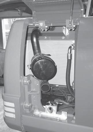
Service cover Air filter
Hydraulic oil return filter
Hydraulic tank breather

Id.No.: 918173
Edition: Sept. 05
Hydraulics
Hydraulic oil tank Cabin
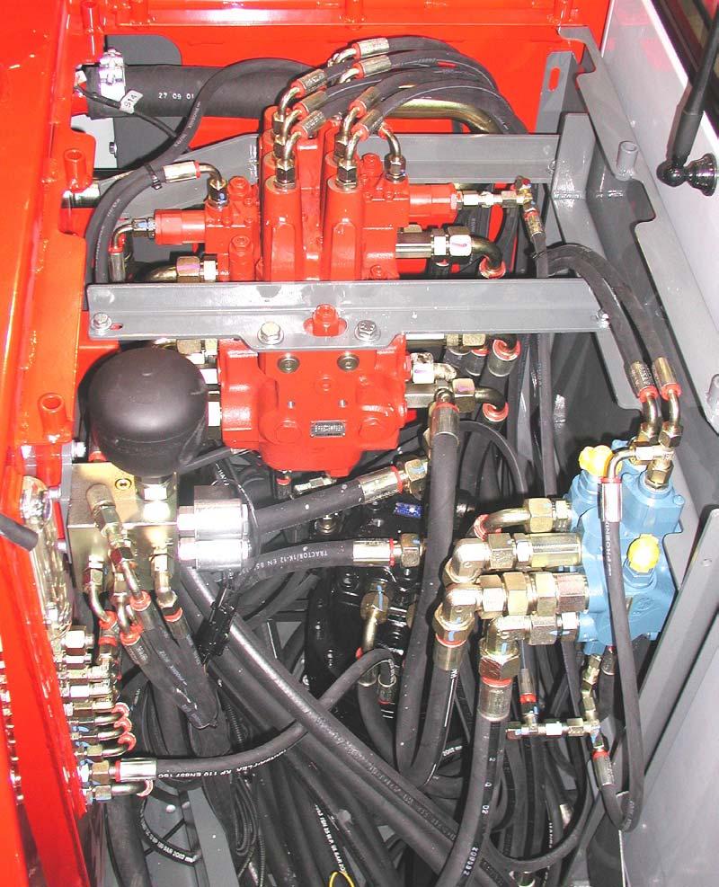
Main valve block
Hydraulic oil level indicator

Pilot oil supply unit
Swivel unit
Secondary valve block
Id.No.: 918173
Edition: Sept. 05
Id.No.: 918173
Edition: Sept. 05
Hydraulics
3. HYDRAULIC PUMP

Type:7008303 ( A8VO28SR3 )
Features: Double variable-displacement axial piston-pump (Band axis pump system)
Common suction hose, Combination power controlled (mech. linked) and single power controller, Three circuit controlled (SR3) + Gear pump (P3)
Pict.: Assembling situation hydraulic pump 7008303
Measuring point MP1
Port P1
Measuring point MP3
Suction port P1 + P2
Double variable pump unit
Type plate
Port P3
Gear pump
Id.No.: 918173
Edition: Sept. 05
Pict.: View from above pump ( 7008303 )

3-circuit power controller Port X3 ( ->>connected with P3 )
Measuring point MP3 (Gear pump)
Q max (M10 x 1,5)
Suction
Measuring point MP2
Measuring port MP1
Port P2 >> Pilot oil supply unit <<Port P1
Description of hydraulic pump 7008303 controller screws functions:
1 .Controller screw for maximum displacement volume ( Q max ): This screw is adjusted to the maximum displacement volume. Adjustment of the flow under conditions of pressureless circulation.
2 .Control characteristics adjustment screw: Used to adjust the controller‘s response speed and the rate of pump delivery control.
IMPORTANT! Proper adjustment is a test bench job, so do not change the factory settings.
Id.No.: 918173
Edition: Sept. 05
Hydraulics
Pump bleeding screw (not active)
Positioning press. port (not active)
Description of hydraulic pump 7008303 controller screws functions (continued)
3 .Controller screw for minimum displacement volume ( Qmin ): To avoid damaging the pump, a certain residual flow must always be maintained (approx. 1.6 gpm — 6 L/min). Adjustment requires a turbine flow meter.
4 .Start of control range controller screw. Used to set control onset threshold.
X3 .3-circuit power controller port: P3 pushs the variable displacement pumps into the Q min position (system supply).

Id.No.: 918173
Edition: Sept. 05
Start of control range Contr.

Id.No.: 918173
Edition: Sept. 05
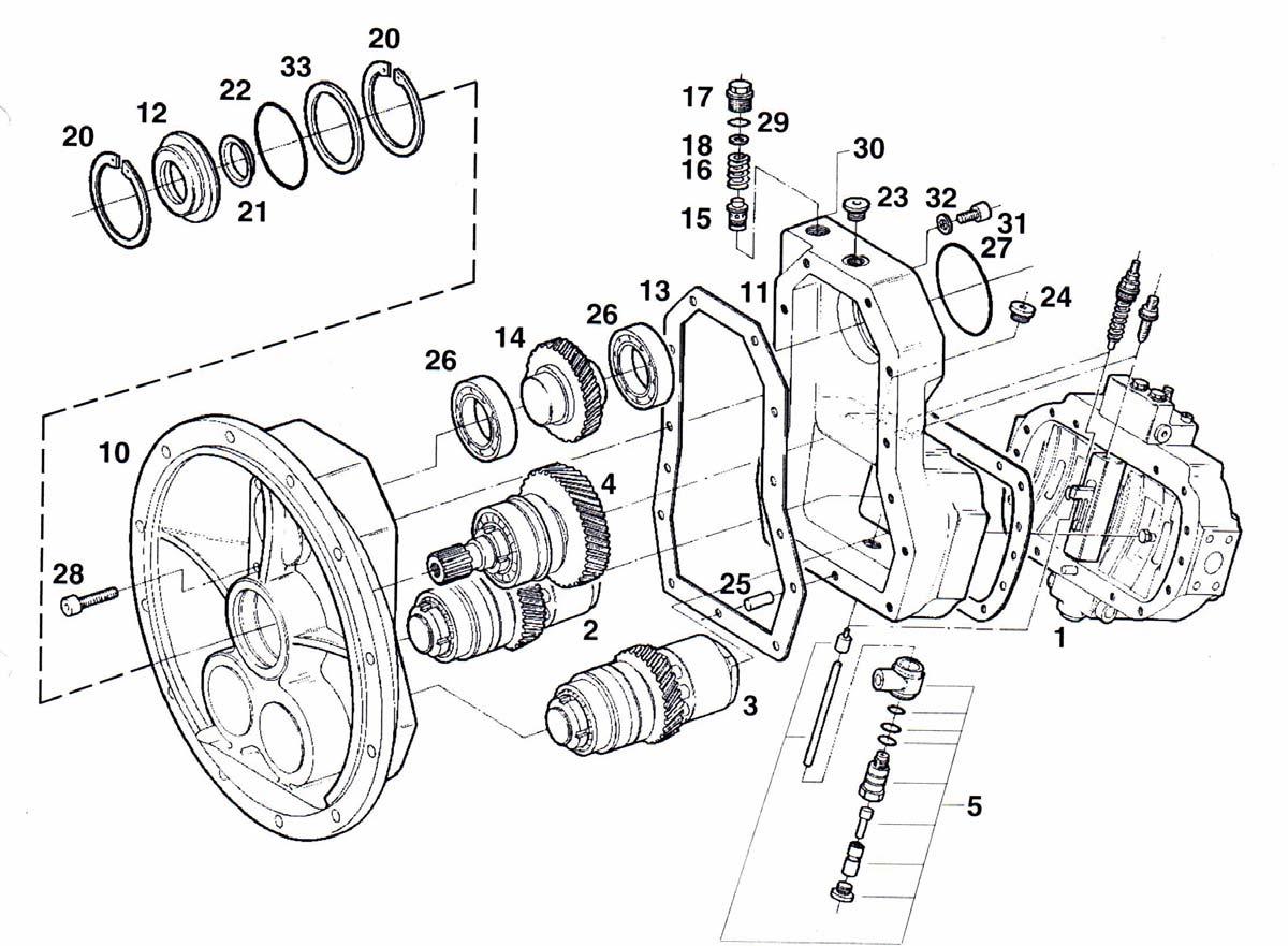
Pict.: Part group structure, double variable-displacement pump (7008303)Notice: assembling position - 180° turned
Start of control range
Control characteristic
Id.No.: 918173
Edition: Sept. 05
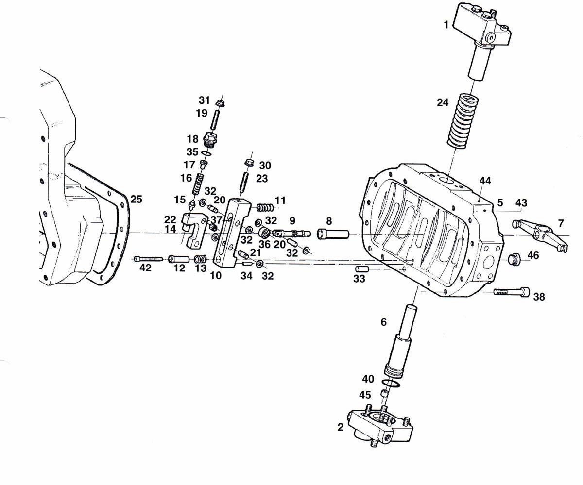
Pict.: Part group structure, double variable-displacement pump (7008303) -
Notice: assembling position - 180° turned
Id.No.: 918173
Edition: Sept. 05
Notice: assembling position - 180° turned
Id.No.: 918173
Edition: Sept. 05
Hydraulics
4. PILOT OIL SUPPLY UNIT
Type:1408610 (blue), 1408615
Function:- Supply of the pressure for the pilot system
- Safety function - arm rest switch,
- Control pressure for the functions 2nd drive speed and swivel motor park brake
- Supply: System accumulator, system drive counter balancing
Pict.: Structure pilot pressure system:
1Pump unit
2Pilot oil supply unit
3Joysticks and foot pedals
4Main valve block
5Measuring points
Id.No.: 918173
Edition: Sept. 05 port P1: >>gear pump P3 port P2: >>variable displacement pump P1 port P3: >>variable displacement pump P2 port T : >>tank port A : >>drive counter-balancing system (main valve block) port PR: >>2nd driving speed (drive unit) valve WK1 - in combination with the push button at the driving lever (formerly port PT - control oil unit 1408610) port BV: >>pilot control valves ( joystick, etc.) via the safety solenoid valve in combination with the sensitive micro-switch in the arm rests (WK2). port PV: >>supply of of setting chamber to swivel motor - release brake
1.Safety valve 725 psi (50 bar) - protects the control oil unit in case of a malfunctioning pressure reducing valve.
2.Shuttle valves - always accept the highest pump pressure for control oil pressure.
3.Pressure reducing valve (PRV) pilot control pressure - ADJUSTMENT POINT (AP).
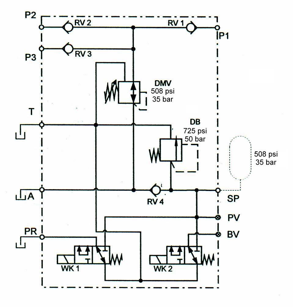
4.Accumulator
Id.No.: 918173
Edition: Sept. 05
Hydraulics
Fig.: Oil Control Unit Port Assignment (version 1408615) to variable-displacement pump P2 to variable-displacement pump P1 to drive counterbalancing system main valve block port SP >> accumulator
2nd drive speedSafety switch switch (WK1)armrest (WK2) to gear pump P3 to pilot control valves

(3)pressure reducing valve AP
(1)Safety pressure valve safety switch solenoid valve armrest
(1) Safety pressure valve 725 psi (50 bar)
(3) Pressure reducing valve ( AP ) - version 1408615 : Metal cap with ring see next page port T - Tank port PR (PT) >> drive motors port SP >> accumulator function swivel motor parking brake (P)
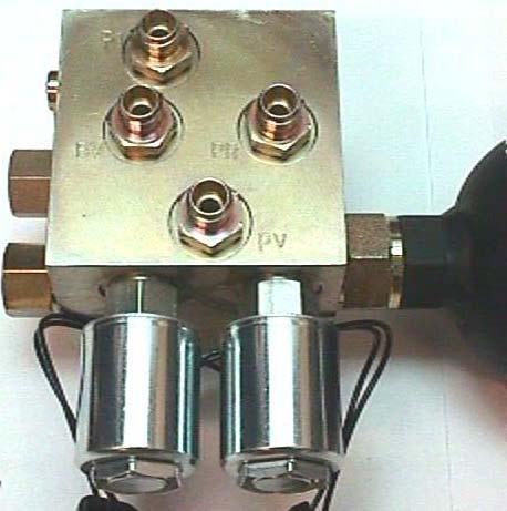
2nd drive speed switch (WK1)
Id.No.: 918173
Edition: Sept. 05
Edition: Sept. 05
Hydraulics
1408610 )
1. pressure reducing valve unit ( AP ) * adjusting washers
2.safety valve (preset to 725 psi / 50 bar) with plastic seal
3.connecting subassembly - accumulator bag
5 - 6shuttle valve subassembly
8 - 9solenoid valves
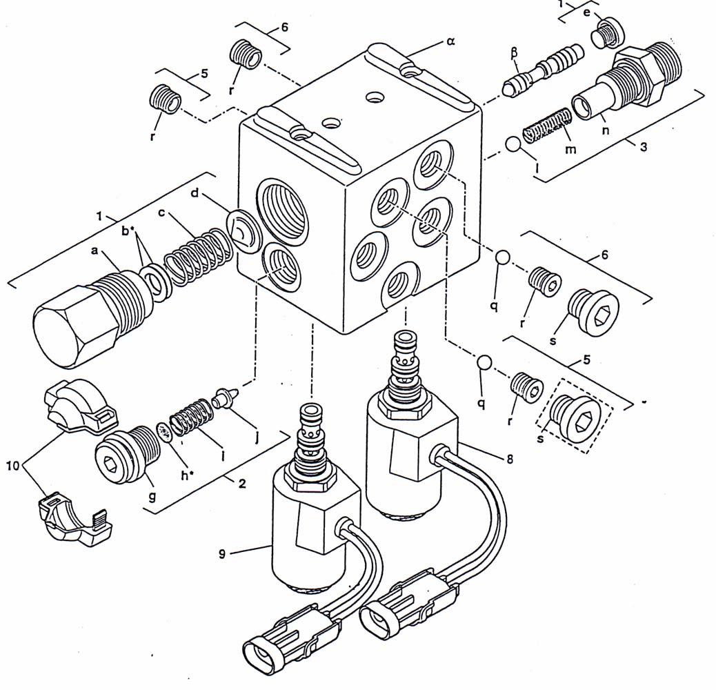
Tightening torques:
1a.111 ft-lbs. (150 Nm)
1e.7.5 ft-lbs. (10 Nm)
2g.74 ft-lbs. (100 Nm)
3n.74 ft-lbs. (100 Nm)
5r.7.5 ft-lbs. (10 Nm)
5s, 6s22 ft-lbs. (30 Nm)
8, 911 - 20 ft-lbs. (15 - 27 Nm)
Id.No.: 918173
Edition: Sept. 05
Theme:Loss of pilot pressure
Solution: Check valves - pilot oil supply unit
Possible problem: The shuttle valves (check valves) do not close correctly (not sealed) => example gear pump P3 supplied oil disappears into pump P1 port => pressure drop in the pilot pressure system by too less oil supply.
Solution: Replace the malfunctioning shuttle valves to external assembled check valves. (Different sealing system) Oil supply unit - version 1408615 - equipped with updated shuttle valve seal system.
Id.No.: 918173
Edition: Sept. 05
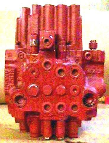
5. MAIN VALVE BLOCK


Type: 7008300
Features :- Combination function of dipper arm cylinder ( both sides )
- Combination function of boom cylinder (bottom side - boom up)
- Leakage free valve for spool boom cylinder (bottom side)
- Leakage free valve for spool dipper stick cylinder (rod side)
- Drive counter-balancing function
- Single primary pressure limiting valve for pump P1 + P2
Id.No.: 918173
Edition: Sept. 05
Hydraulics SERVICE MANUAL
8 0 0 2
Legend pict.: Sections main valve block 7008300 - View A
1.Boom offset
2.Dipper arm (cylinder rod side)
3.Leakage free valve - spool dipper arm cylinder (rod side)
4.Boom (2) combination section
5.Auxiliary hydraulics
6.Drive left
7.Primary - pressure limiting valve P1 + P2 ( AP )
8.Dipper arm (2) combination section
9.Boom
10.Leakage-free valve - spool boom cylinder (bottom side)
11.Bucket
12.Drive right
Pumps / section relation - Main valve block 7008300
12Function Drive right
11Function Bucketsupplied by pump P1
9Function Boom
8Function Dipper arm (2) summ.
1Function Boom offset
2Function Dipper arm
4Function Boom (2) combinationSupplied by pump P2
5Function Auxiliary hydraulics
6Function Drive left
Id.No.: 918173
Edition: Sept. 05
Id.No.: 918173
Edition: Sept. 05
Id.No.: 918173
Edition: Sept. 05
Id.No.: 918173
Edition: Sept. 05
Edition: Sept. 05
Id.No.: 918173
Edition: Sept. 05
Id.No.: 918173
Edition: Sept. 05
Single Operation
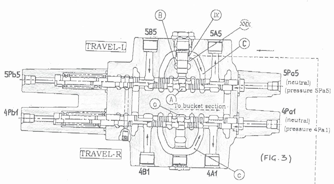
1-1Spool for TRAVEL LEFT / RIGHT
When the 4Pa1 ( 4Pb1 ) port is pressurized and the “TRAVEL R” spool is switched (Fig. 3), neutral oil passage (a) is shut and the oil which comes from 4P port flows in the cylinder port 4A1 ( 4B1 ) through passage (c). Also, the return oil from the cylinder port returns to the tank through 4A1 ( 4B1 ).
When the 5Pa5 (5Pb5) port is pressurized and the “TRAVEL L” spool is switched (Fig. 3), the oil which comes from 5P flows in the cylinder port 5A5 ( 5B5 ) through parallel passage (B), shuttle spool ( VIII ) passage (14) and passage (C). Moreover, the return oil from the cylinder port returns to the tank through 5B5 ( 5A5 ). Some of the oil which comes from 5P push poppet up through choke ( XXIX ) and flows in the cylinder port 5A5 ( 5B5 ) through passage (C).
1-2Spool for RESERVE
When the 5Pa4 ( 5Pb4 ) port is pressurized and the “RESERVE” spool is switched (Fig. 4), neutral oil passage (A) is shut and the oil which comes from 5P push poppet ( X ) up and flows in the cylinder port 5A4 ( 5B4 ) through passage (D). Moreover, the return oil from the cylinder port returns to the tank through 5B4 ( 5A4 ). This section can install the overload relief valve in the cylinder port 5A4 ( 5B4 ).
1-3Spool for BUCKET
When the 4Pa2 ( 4Pb2 ) port is pressurized and the “BUCKET” spool is switched (Fig. 4), neutral oil passage (a) is shut and the oil which comes from 4P (through parallel passage (b)) push check valve ( XI ) up and flows in the cylinder port 4A2 ( 4B2 ) through passage (d). Also, the return oil from the cylinder port returns to the tank through 4B2 ( 4A2 ).
When TRAVEL SPOOL L&R are operated, the bucket can be operated by choke ( XXX ).
Id.No.: 918173
Edition: Sept. 05
1-2,3Spool for RESERVE / BUCKET( FIG. 4 )
Id.No.: 918173
Edition: Sept. 05
Hydraulics
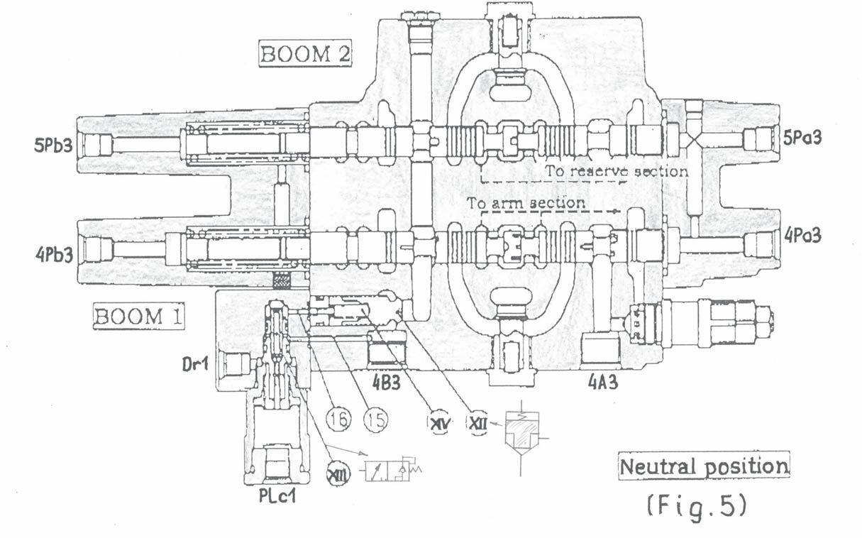
1-4Spool for BOOM
A)NEUTRAL ( Fig. 5 )
The anti-drift valve is installed at the cylinder bottom side of boom 1. At neutral position, the poppet ( XII ) is shut securely by the pressure supplied by the spring through passage (15), spool ( XIII ) and passage (16) from 4B3.
1-4Spool for BOOM
B)BOOM UP ( Fig. 6 )
When the 4Pb3 port is pressurized and the “BOOM 1” spool is switched (Fig. 6), neutral oil passage (a) is shut and the oil coming from 4P (through parallel passage b) pushes check valve ( XII ) up and flows in the cylinder port 4B3 through passage (e) and poppet ( XII ).
If “BOOM 1” is switched, “BOOM 2” is changes by pressure through passage (13). The oil which came from 5P passes parallel passage (B) and pushes check valve ( XVI ) up. Then it goes to 4B3 port through passage (E) and (5). The return oil from the cylinder port 4A3 returns to the tank through the spool for “BOOM 1”.
C)BOOM DOWN ( Fig. 7 )
When the 4Pa3 ( 5Pa3 ) port is pressurized and the “BOOM 1” spool is switched (Fig. 7), the neutral oil passage (a) is shut and the oil which coming from 4P (through parallel passage b) pushes check valve ( XV ) up and flows in the cylinder port 4A3 through passage (e). At the same time as “BOOM 1” spool is switched, “PLc1” port is pressured and spool ( XIII ) is switched. As a result, the pressure of spring room ( XIV ) is decreased and poppet ( XII ) is opened. The oil which come from 4B3 goes to tank.
Id.No.: 918173
Edition: Sept. 05
1-4Spool for BOOM( FIG. 6 )
Id.No.: 918173
Edition: Sept. 05
1-4Spool for BOOM( FIG. 7 )
Id.No.: 918173
Edition: Sept. 05
1-5Spool for DIPPER ARM
A)DUMP (Dipper arm up / - cylinder rod side) ( Fig. 9 )
When the 5Pb2 ( 4Pb4 ) port is pressured and the “ARM1” spool is switched (Fig. 9), neutral oil passage (A) is shut and the oil which comes from 5P pushes check valve ( XIX ) up and flows in the cylinder port 5B2 through passage (G) and poppet ( XXII ).
At the same time, a part of the oil which comes from 5P goes to 5B2 port through passage (B) choke ( XXXI ), check valve ( XVIII) and passage (G).
If “ARM 1” is switched, “ARM2” is changed by pressure through passage (17).
The oil supplied from 4P push the check valve up after neutral oil passage (a) and passage (3) passing and flows in the 5B2 port.
A part of oil from 4P port pushes up the tandem check valve ( XXI ), passes passage (4) (G) and arm1 spool, and flows into port 5B2. The return oil from the cylinder port returns to the tank through 5A2 and arm 1 spool.
B)CROWD ( Dipper arm down / - cylinder bottom side ) ( Fig. 10 )
When the 5Pa2 port is pressured and the “ARM 1” spool is switched (Fig. 10), neutral oil passage (A) is shut and the oil coming from 5P pushes check valve ( XIX ) up and flows into the cylinder port 4A2 through passage and spool (G).
Some of the oil from the 5P port flows into the port 5A2 through passage (B), choke ( XXXI ), check valve ( XVIII ) and passage (G).
This choke is equipped to decide the priority of the operation simultaneously. At the same time as switching the arm 1 spool, PLc2 port is pressured and spool ( XXII ) is operated. As a result, the spring room ( XXIV ) is decompressed and poppet ( XXII ) is opened. The oil from the cylinder port returns to the tank through arm 5B2.
At the same time as switching the arm 1 spool, 4Pa4 port is pressured and arm 2 spool is switched. The oil supplied from 4P pushes the check valve ( XX ) up after neutral oil passage (a) and passage (3) is complete and flows into the 5A2 port through passage (G) and arm 1 spool. Some of oil from 4P port flows into port 5A2 through check valve ( XXI ) and passage (4).
Id.No.: 918173
Edition: Sept. 05
1-5Spool for DIPPER STICK ( ARM ) ( FIG. 9 )
Id.No.: 918173
Edition: Sept. 05
1-5Spool for DIPPER STICK ( ARM ) ( FIG. 10 )
Id.No.: 918173
Edition: Sept. 05
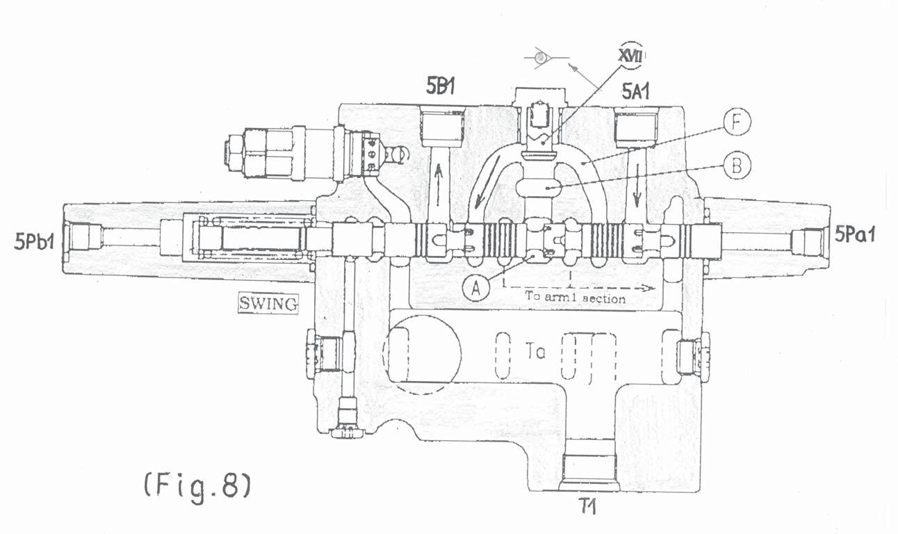
1-6Spool for BOOM OFFSET CYLINDER ( SWING )
When the 5Pb1 ( 5Pa1 ) port is pressurized and the “SWING” spool is switched (Fig. 8) neutral oil passage (A) is shut and the oil which comes from 5P port flows into the cylinder port 5B1 ( 5A1 ) through passage (B), poppet ( XVII ). The oil from the cylinder port returns to the tank through 5A1 ( 5B1 ).
Id.No.: 918173
Edition: Sept. 05
1-7 RELIEF VALVE
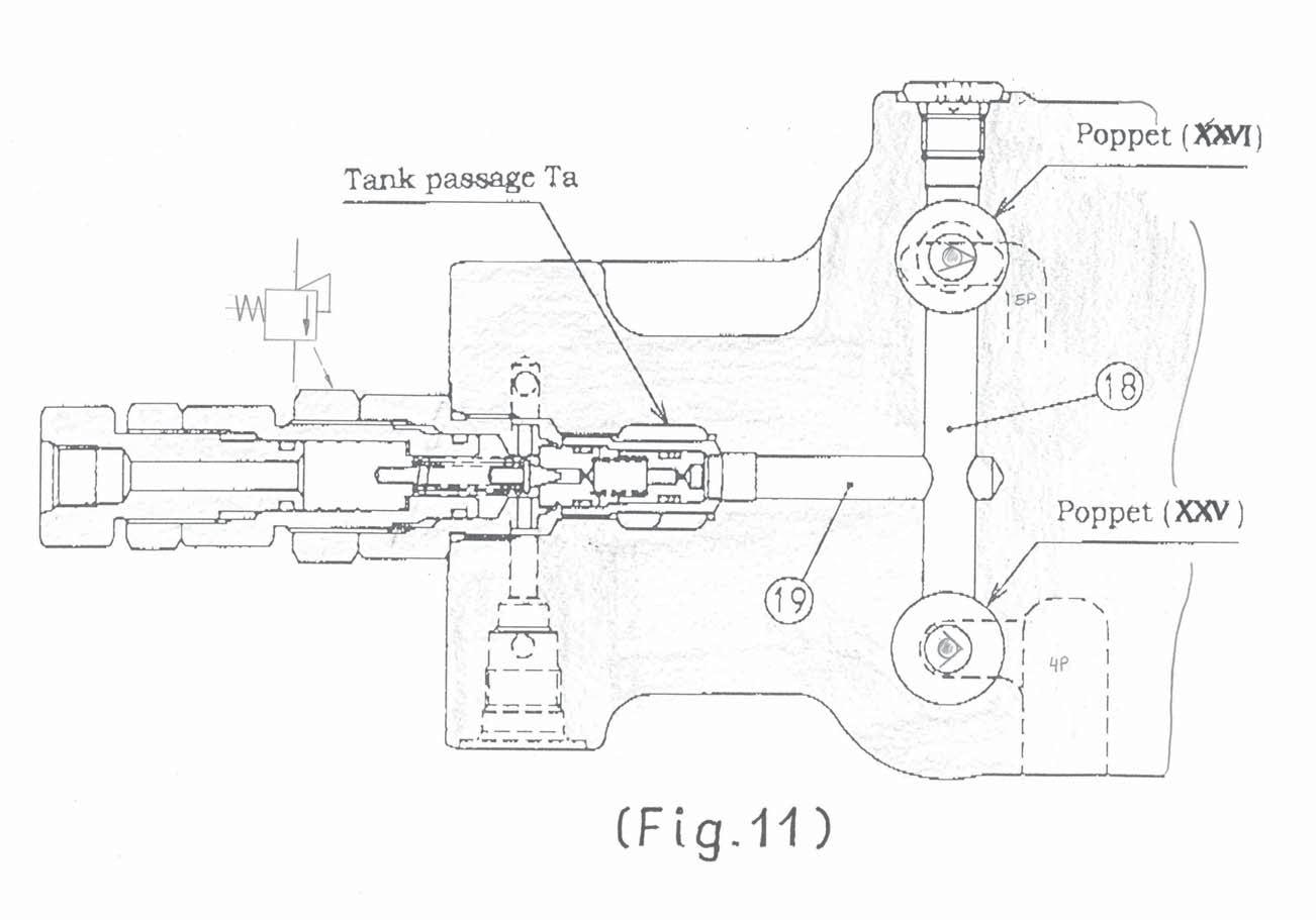
A)MAIN PRESSURE LIMITING VALVE ( Fig. 11 )
The oil which comes from 5P passes parallel passage (B) and pushes the poppet ( XXVI ) up, then it goes into passage (19) through passage (18).
The oil which comes from 4P passes neutral passage (a) and pushes the poppet ( XXV ) up, then it goes in passage (19) through passage (18).
The main pressure limiting valve limits the pressure of 4P (pump 1) and 5P (pump 2) to the setting pressure.
B)SEC. PRESSURE LIMITING VALVE (Overload relief valve)
The secondary pressure limiting valve installed at the cylinder port of the boom, the arm and bucket prevents the pressure of actuators from rising abnormally. When set pressure of this valve is higher than main pressure limiting valve, the highest pressure is restricted by this valve. This valve has the function to prevent the cavitation when the pressure of the cylinder port becomes negative pressure.
Id.No.: 918173
Edition: Sept. 05
Hydraulics
Function Drive Counter-Balancing System
General:
Without drive balancing:If an arm function is activated during straight travel, travel direction is not maintained (P1, P2 supply one drive unit, each).
All units are equipped with drive counter-balancing function.
With drive balancing:
The unit maintains straight travel if an arm function is activated. Both drive motors are supplied by pump P1 - P2, supplying the arm functions. The drive counter-balancing system is activated only if both driving valves are active.
Function:
See the drive counter-balancing system circuit diagram:
- Both spool valves for driving and one arm function must be actuated.
- The drive counter-balancing system (main valve block) is activated because of a pressure build-up (port PP / A).
- P2 supplies the remaining sections.
Switching pressure drive counter-balancing valve:
Pump / main valve block sections - relation - with active drive counter -balancing:
12Function Drive rightSupplied by pump P1
6Function Drive left
11Function Bucket
9Function Boom
8Function Dipper arm (2) combinationSupplied by pump P2
1Function Boom offset
2Function Dipper arm
4Function Boom (2) combination
5Function Auxiliary hydraulics
Id.No.: 918173
Edition: Sept. 05
Id.No.: 918173
Edition: Sept. 05