20 minute read
Tab.: Lift capacity chart - Standard boom


Max.Allowable load with extended dipper arm
A Overhang from the center of the turntable
B Height of load fixing point
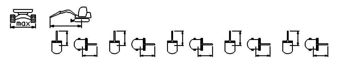
* Lift capacity restricted by the hydraulics
All chart figures are given in lbs. (kg) rated on level, firm ground without bucket.
Dozer blade support in drive direction.
Dozer blade support 90° to drive direction.
If a bucket or other attachment is mounted, the lifting capacity, or tilting load is reduced by the empty weight of the attachment.
Position on solid subsoil and without bucket.
Design fundamentials: according to ISO 10567
The lifting power of the compact excavator is limited by the setting of the pressure controls valves and stabilizer system. Neither 75% of the static tilting load nor 87% of the hydraulic lifting capacity are exceeded.
Id.No.: 918173
Edition: Sept. 05
5. HYDRAULIC SYSTEM
16
Pressure Adjustment
17
(1)...General - Hydraulic oil temperature: 133 - 122°F (45 - 50°C)
(2)...Settings at max. engine rpm (see Maintenance chap.)
(3)...Settings at min. engine rpm (see Maintenance chap.)
QUANTITIES
32 gals. (122 L)
46 gals. (173 L)
AUXILIARY HYDRAULICS
Pressure controlled oil flow - auxiliary hydraulic
Conditions:
1) Pressure = Pressure setting at the attachment
2) Tolerance of the listed oil flow: +0.3 / -0.5 gpm (+1 / -2 L/min)
3) Measuring point for the oil flow = couplers at the dipper arm
Clearance - Hose burst protection valves (inside hose versions) Dozer
Assembled
6. DIESEL ENGINE SPECIFICATIONS
Diesel engine specifications
- 185°F (71 - 85°C) 225 - 235°F (107 - 113°C) 1-3-4-2 40 A / 12 V
12 V / 88 Ah x 43" (13 x 1090 mm)
76 - 83 lb-ft (102.9 - 112.7 Nm)
M11x1,25 )
40 - 43 lb-ft (53.9 - 58.8 Nm)
M10x1,0 )
80 - 87 lb-ft (107.9 - 117.7 Nm)
M11x1,25 )
137 - 152 lb-ft (186.3 - 205.9 Nm) ( M14x1,5 )
23.8 gals. (90 L)
10.8 / 5.3 qts (10.2 / 5 L)
9 qts. (8.7 L)
BP Vanellus FE API SF-CD + SAE 10W40, API gr.cl. CD
Id.No.: 918173
Edition: Sept. 05
This page intentionally left blank
Id.No.: 918173
Edition: Sept. 05 every 10 hevery 50 hevery 250 hevery 500 hevery 1000 h (daily)(weekly)(6 months)(12 months)(18 months)annually
Hydraulic pump fastening boltsO cylinders)O
Id.No.: 918173
Edition: Sept. 05
FunctionO Leakage (cooling and heating circuit)O W O R K I N G E Q U I P M E N T check Servicing activity component H E A T I N G O - Check <> - Change/Replace X - Clean <> (1) - Change/Replace the first time every 10 hevery 50 hevery 250 hevery 500 hevery 1000 h (daily)(weekly)(6 months)(12 months)(18 months)annually G E N E R A L
Id.No.: 918173
Maintenance - General (according to the Operator‘s Manual)
The reliability and service life of machines are to a great extent influenced by care and maintenance.
Cleaning: In the first three months, wash the machine only with cold water (do not use high-pressure or steam-jet cleaning). After the first three months, the minimum distance between the spraying nozzles and the machine must be 12 inches (30 cm), and the water temperature shall not be higher than 140°F (60°C). Do not use aggressive cleaning agents.
Performing specified maintenance is a primary advantage to the owner of a machine. Perform maintenance as specified by the manufacturer. Failure to perform the specified maintenance will result in exclusions of warranty.
For engine maintenance requirements, refer to the engine operating instructions. Using lubricants that are not in compliance with the manufacturer’s recommendations will void the warranty.
Before starting maintenance or repair, please read all procedures, warnings and cautions to avoid injury or equipment damage.
Before starting maintenance or repair work, lower the working equipment to the ground. Apply locking and safety levers.
- Bleed residual pressure off the hydraulic system.
- Let the engine cool down.
If work must be done with the machine lifted, it must be securely supported. Provide for sufficient ventilation when performing maintenance or repair work in a closed room. Dispose of oil filters (oil, etc.) as required by environmental law.
When working on and/or below the compact excavator, place a warning sign on the operator’s seat and/or someplace clearly visible and legible at the compact excavator. Remove the ignition key.
Id.No.: 918173
Edition: Sept. 05
2. LUBRICANTS
USED ASNOTES LUBRICATION TYPE
Engine oil
Hydraulic oil
10W40 (Norm)
BP Vanellus FE
APISF-CD + SAE 10W 40
FINA Kappa SE10W40
Q8 T660-10W40
HVLP 46 (Norm)
BP Energol SHF 46
FINA Hydran TSX 46
Q8 Heller 46
Bio oil BP Biohyd SE S46
Turn table:
Teeth
Ball bearings
Drive gears
BP Energrease OG (White)
BP Energrease L 21 M
Energear Hypo EP 90 API GL 5
FINA Pontonic MP85W90APIGL5
Q8 T55 85W90
RK 15, RK20S SGXP 220
Boom, dipper arm, etc.
BP Energrease L 21 M
Gleitmo 805 (For initial greasing of the bolts )
Track tension cylinder
Planetary gear
Fix and float axles
Distribution gear
Each Lubr. point
Conditions:
BP Energrease L 21 M
Wheeled excav. SAE 90 Hypoidöl (GL 5)
FINA Pontonic MP85W90APIGL5
Q8 T55 85W90
BP Energrease L 21 M
Engine oil: at -13 – 104°F (-25 – 40°C) Outside temperature
Grease: at -13 – 104°F (-25 – 40°C) Outside temperature
Id.No.: 918173
Edition: Sept. 05
3. LUBRICATION CHART
Lubrication points to be lubricated daily - blue plugs. Lubrication points to be lubricated weekly - green plugs.
Id.No.: 918173
Edition: Sept. 05
4. HYDRAULIC SYSTEM
General instructions:
-Always bleed the hydraulic system before performing maintenance and repair work.
-For hydraulic settings, please refer to the Technical Data chapter.
-Before each pressure test, the machine must be at operating temperature—hydraulic oil temperature at least 122°F (50°C).
-Primary pressure limiting valves (PPLV) must be adjusted at maximum engine speed. (Refer to the Technical Data chapter).
-The pressure drop (delta P between maximum (full throttle) and minimum (idle) diesel engine speed) is tested at unloaded condition.
Pressure Test
Features:
-One Primary-pressure limiting valve for P1 + P2 (Main valve block functions).
-One Primary-pressure limiting valve for P3 (Second valve block functions).
-Mearsuring ports at the hydraulic pump and at the pilot oil supply unit.
4.1 Pressure test of regulation pump P1
Functions:boom 1, bucket, drive right.
4.1.1
PPLV 1 setting check :
a)Connect pressure gauge to measuring port MP 1.
b)With the engine at full throttle, move the boom (cylinders bottom side) up to the stop.
c)Check and note the pressure.
4.1.2
Pressure drop check :
d)With the engine at full throttle, move the boom (at the bottom side) up to the stop (similar to step 4.2.1.b).
e)While holding the boom cylinder at max. pressure, reduce the diesel engine speed quickly from max. to min speed. Check and record the pressure drop. The pressure drop should not exceed more than 10% of the setting. (This is an approximate value, and only applies to primary pressure limiting values.) An excessive pressure drop is an indication of a possible leak.
f g)If any settings deviate from the values in the “Hydraulic System“ section in the “Technical Data“ chapter, please set the correct pressure at the primary pressure limiting valve (PPLV1) or check for and repair the cause for the pressure drop - then repeat steps a - f. h)An excessive pressure drop could be an indication of leakage. (e.g.: def. O-Ring in secondary valve, etc.)
)Check the setting and pressure drop of function boom cylinder rod side, bucket cylinder bottom and rodside, driving left vorward / reverse in the same manner as described in items 2.2.1 and 2.2.2.
Id.No.: 918173
Edition: Sept. 05
4.2 Pressure test of regulation pump 2
Functions:dipper arm 1, drive left, auxiliary hydraulic, boom offset
4.2.1 Check of setting PPLV 1 : i) Connect a pressure gauge to measuring port MP 2. j) At maximum engine speed, move the dipper arm (cylinder bottom side) in to the stop. k) Check and record the pressure.
4.2.2 Check of pressure drop : m) Check and record pressure drop of the individual functions in the same manner as steps d - g. n) Check the settings and pressure drop of the dipper stick (cylinder rodside) and drive right functions in the same manner as steps 4.1.1 - 4.1.2. Record the result. p) If any settings deviate from specifications, set the correct pressure at the primary pressure limiting valve (PPLV1) at the main valve block or check the reason for the pressure drop. Then, repeat steps i - p.
An excessive pressure drop might indicate leakage (e.g.: defective O-ring in secondary valve, etc.).
Pressure test for auxiliary hydraulic system:
The auxiliary hydraulics function shows the settings of the primary pressure limiting valve PPLV1 at measuring port MP 2 if no optional secondary pressure limiting valve is installed.
- With ball valve opened - unpressurized return flow (measurement: system building pressure).
- If there are optional secondary valves AH installed, the values in the “Hydraulic System“ section in the “Technical Data“ chapter may be incorrect, because SPLV are set individually.
4.3 Pressure test of gear pump P3
Functions: dozer blade, swivelling
4.3.1 Check of setting PPLV 2 : r) Connect a pressure gauge to measuring port MP 3 . s) With the engine at maximum speed, move dozer blade (cylinder bottom side) to stop position. t) Check and record the pressure and pressure drop. u) The swiveling function is supplied by pump P3, though the operating pressure is limited by the secondary pressure limiting valves (SPLV) located at the swivel motor - see swivel motor. ( > Check of pressure drop only permissible with primary control values.)
4.4 Pilot Pressure Test:
Functions: hydraulic pilot control
4.4.1 Check of setting PRV: a) Connect the pressure gauge to measuring port MP 4. b) Actuate joystick. c) Check pressure and/or set it at the pressure reducing valve (PRV) at the pilot oil supply unit.
IMPORTANT: Also refer to Test Report - Pressure Test on the following pages.
Id.No.: 918173
Edition: Sept. 05
PLVPressure limiting valve PRVPressure reducting valve
(1) Note: Pressure settings correspond to the excavator serial no. (Always compare with the pressure setting in the “Technical Data“ chapter.)
(2) Note: Setting is only correct without secondary pressure limiting valves.
(3)Swivel function: see the “Technical Data“ and “Maintenance“ chapters.
(4)See the “Technical Data“ chapter“:
PLVPressure limiting valve
PRVPressure
(1) Note: Pressure settings correspond to the excavator serial no. (Always compare with the pressure setting in the “Technical Data“ chapter.)
(2) Note: Setting is only correct without secondary pressure limiting valves.
(3)Swivel function: see the “Technical Data“ and “Maintenance“ chapters.
(4)See the “Technical Data“ chapter“:
PLVPressure limiting valve
PRVPressure reducting valve
(1) Note: Pressure settings correspond to the excavator serial no. (Always compare with the pressure setting in the “Technical Data“ chapter.)
(2) Note: Setting is only correct without secondary pressure limiting valves.
(3)Swivel function: see the “Technical Data“ and “Maintenance“ chapters.
(4)See the “Technical Data“ chapter“: version 7008490, 7008501 - different settings
PLVPressure limiting valve
(1) Note: Pressure settings correspond to the excavator serial no. (Always compare with the pressure setting in the “Technical Data“ chapter.)
(2) Note: Setting is only correct without secondary pressure limiting valves.
(3)Swivel function: see the “Technical Data“ and “Maintenance“ chapters.
(4)See the “Technical Data“ chapter“:
Note:
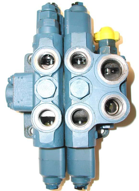
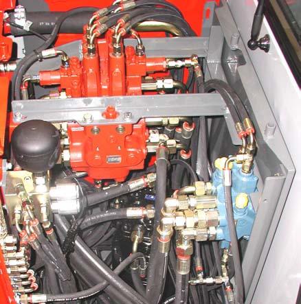
Pict.: Position Primary - Pressure limiting valve ( PPLV 1 ) - Main valve block
Primary- Pressure limiting valve PPLV 1 ( AP ) at the main valve block
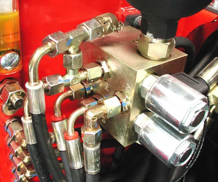
Pict.: Position Primary-Pressure limiting valve ( PPLV 2 ) - Second valve block
Primary- Pressure limiting valve
PPLV 2 ( AP ) at the second valve block
Id.No.: 918173
Edition: Sept. 05
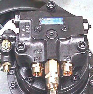
Pict.: Position Secondary - Pressure limiting valves swivel motor ( SPLV )
SecondaryPressure limiting valveSwivel motor
Pict.: Position Pressure Reducting valve ( PRV ) - pilot pressure At the pilot oil supply unit
Pressure reducting valve ( AP )
SecondaryPressure limiting valveSwivel motor
Id.No.: 918173
Edition: Sept. 05
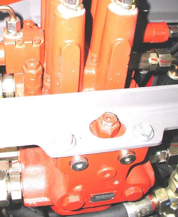
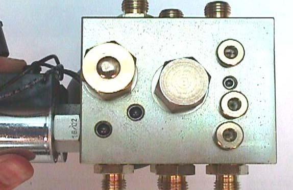
Pict.: Position Measuring ports ( MP 1 - 3 ) Hydraulic pump
MP 1MP 3
Pict.: Position Measuring ports ( MP4 ) at the pilot oil supply unit
Id.No.: 918173
Edition: Sept. 05
.
3. HYDRAULIC PUMP
Bleeding of hydraulic pump
- Shut down device
- Open the breathing / bleeding filter
- Open screw plug air bleed screw
- Drain a small amount of hydraulic oil via the air bleed screw
Bleeding of Suction Line
The measuring port mounted on the pump suction line (in the engine compartment) is provided for venting the pump suction line.

Id.No.: 918173
Edition: Sept. 05
4. HOSE BURST PROTECTION VALVE
Clearance Dimension Check
Safety regulations provide for the installation of hose burst protection facilities in dozer blade cylinders and in tilting cylinders. If these valves are missing, there may be liability in case of an excavator accident.
> SETTING of GAP DIMENSION “S” :
1. Loosen the two nuts.
2. Adjust the gap “S” by means of a gauge (see the Technical Data chapter).
3. Tighten the nuts lightly by hand and fix them cautiously against each other.
5. DRIVE UNIT Gear Box .
> Check:- Open the oil level plug ( 2 ).
- The oil level must be at the oil level port.
> Changing :- Open the oil filler screw ( 1 ) and the drain plug ( 3 ).
- Drain oil and collect it in an appropriate container.
- Replace and tighten the drain plug and open oil level plug.
- Fill the gearbox with fresh oil through the filler hole unit the gear oil emerges from the level hole. Refer to the list of lubricants in the Technical Data chapter for proper gearbox oil grade and type.
- Replace and tighten the oil level and filler plugs.
IMPORTANT!: Check for gearbox leakage and for proper gearbox oil level according to the maintenance schedule.
Dispose of waste oil as provided by environmental laws.
Gear box oil level
Id.No.: 918173
Edition: Sept. 05
6. SWIVEL UNIT
Gear Box - Swivel unit 7008501 .
> Check:
- Check fluid level at level inspection / refill plug.
- The level should be flush with the inspection plug.
> Refilling / changing :
- Open drain hose (1) (access from the chassis floor plate - engine).
- Open air bleed screw (2).
- Drain gear oil into an appropriate container.
- Close drain hose (1).
- Fill the gearbox with oil through air bleed screw (2) to maximum level. Refer to the list of lubricants in the Technical Data chapter for proper gearbox oil grade and type.
- Close air bleed screw (2)
Dispose of waste oil according to environmental law.
Gear Box - Swivel Unit 7008490 (Serial No.: AB01599 and higher)
> Check / refilling / changing : As described in Swivel Unit 7008490 in the Hydraulic System chapter, the gear box is “maintenance-free”.
(lubricated with fresh hydraulic oil )
Swivel Motor .
> Check / settings : Following the pressure test - hydraulic system (Checklist)
Id.No.: 918173
Edition: Sept. 05
7. DIESEL ENGINE
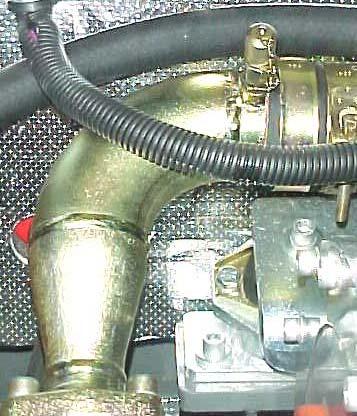
Fuel system
> BLEEDING :
1) Check the level in the fuel tank.
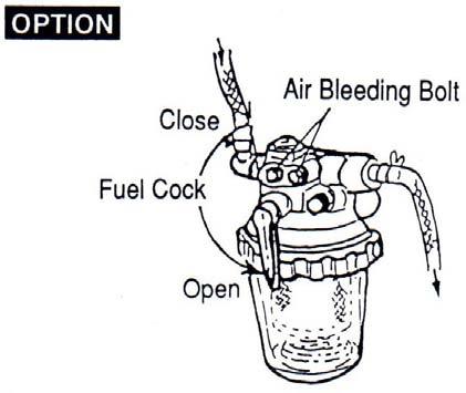
2) Turn the fuel valve to the “Open” position (see pict. 2 water separator).
3) Open the air bleed bolts and valves on the filters.
4) Use the fuel priming pump to pump the fuel into the fuel system.
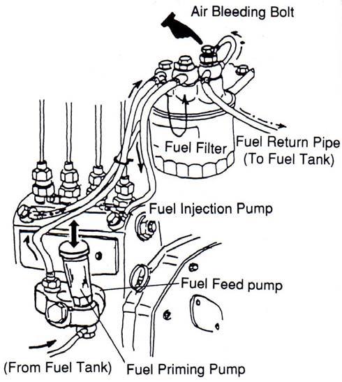
5) Bleed the system until the fuel is free of air bubbles. Close the air bleeding bolts.
6) Repeate this procedure in the following order: water separator, fuel filter, fuel injection pump.
.
> DISMANTLING and INSTALLATION of filter element:
Any water in the preliminary filter housing (plastic ring in floating position) must be drained.
1.Turn the shut-off valve counter-clockwise on the preliminary filter housing.
2.Open and drain preliminary filter housing.
3.Remove and clean preliminary filter element. Pay close attention to parts order for reassembly.
4.Reassemble in reverse order from reassembly (plastic ring / spring / filter).
5.Vent fuel system.
Id.No.: 918173
Edition: Sept. 05
Fuel Filter .
> DISMANTLING and INSTALLATION of filter cartridge :
The main filter cartridge must be replaced at regular intervals according to the maintenance schedule.
1.Turn the shut-off valve on the fuel filter housing counter-clockwise.
2.Dismantle filter cartridge and replace it with a new one.
3.Vent fuel system.
Air Filter .
> DISMANTLING and INSTALLATION of filter element:
1.Remove the filter housing cover.
2.Remove the wing nut securing the air filter element. Remove the air filter element and replace it.
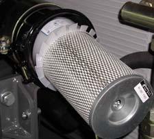
3.Check the safety element and replace it if necessary.
4.Pull dust cap out of the filter housing cover and empty the cover.
5.Replace the filter housing cover with the “TOP“ marking pointing up.
V- Belt .
> TENSION CHECK:
1.Open the engine cover.
2.Check V-belt tension by pressing the V-belt down between the water pump and the generator pulley (deflection approx. 0.4 – 0.6 in. [10 – 15 mm] – tension o.k.).
3.For tightening, refer to the figure below.
Id.No.: 918173
Edition: Sept. 05 tension bracket tube alternator water pump crankshaft alternator
Tappet Clearance .
> CHECK and ADJUSTMENT : valve cap normal abnormal wear adjusting screw tappet clearance lock nut
1.Checks and adjustments shall be done when the diesel engine is cold.
2.Remove the valve cover.
3.Put the relevant cylinder to the top dead center of the compression cycle.
4.Check valve caps for abnormal wear.
5.Measure tappet clearance by means of gauge between the rocker arm and the valve head. Clearance should be 0.006 — 0.010 in. (0.15 — 0.25 mm).
6.If necessary, adjust tappet clearance using the adjusting screw and lock nut.
7.Replace the valve cover gasket (replace the gasket with a new one, if necessary).
8.Replace the valve cover.
Id.No.: 918173
Edition: Sept. 05
Compression .
> Check:
1.Start the engine and run it until it reaches operating temperature.
2.Remove the plug for the cut-off solenoid to se the injection pump to zero delivery.
4.Crank the engine 2 or three revolutions. Note: Do not attempt to start the engine.
5.Mount compression gauge on the cylinder you want to measure.
6.Crank the engine with the starter and read the pressure indicated by the pressure gauge.
• Specified value: 508 +/- 14.5 psi (35 +/- bar) @ 250 rpm.
• Limit value: 406 +/- 14.5 psi (28 +/- 1 bar) @ 250 rpm.
Injection Nozzles .:
> PRESSURE TEST
1.Remove the injection line and the injection nozzles.
2.Connect the injection nozzle to the high-pressure line of the nozzle tester.
3.Slowly increase pressure until the nozzle ejects fuel and read the pressure indicated by the pressure gauge. Injection pressure should be 3191 — 3336 psi (220 — 230 bar).
4.If the injection pressure is too low, replace the spacer in the nozzle with the thicker one. If the pressure is too high, replace the spacer with a thinner one.
Indirect injection system: increase adjusting washer thickness by 0.004“ (0.1 mm) = 101.5 –145 psi (7-10 bar)
Direct injection system: increase adjusting washer thickness by 0.004“ (0.1 mm) = 275.6 psi (19 bar) nozzle testing device injection nozzle
Id.No.: 918173
Edition: Sept. 05
Injection Nozzles
Nozzle setup: Indirect injection upper nozzle union adjusting washers compression spring compression spring seat compression spring centering device injector needle nozzle body nozzle direct injection oil return line upper nozzle union adjusting washers compression spring compr. spring seat compression spring centering device lower nozzle union centering pin injector needle nozzle body lower nozzle union
Id.No.: 918173
Edition: Sept. 05
> CHECKIN G THE NOZZLE JET
1.Remove the injection line and the injection nozzles.
2.Connect the injection nozzle to the high pressure line of the nozzle tester.
3.Quickly create pressure until the nozzle ejects fuel (ejection 3 — 4 times).
4.Hold a while sheet of paper about 12 in. (30 cm) away from the nozzle and let the nozzle eject fuel.
5.The nozzle jet must creat a circle on the paper.
6.Check the nozzle for drips after it has ejected fuel.
7.Create a pressue of approx. 290 psi (20 bar) below injection pressure and check whether fuel escapes from the nozzle.
8.If nozzles are replaced/replaired, they must always be checked prior to installation using a nozzle testing device (spraying, leakage, injection pressure).
Id.No.: 918173
Edition: Sept. 05
Fuel injection pump .
> DISMANTLING / INSTALLATION:
The injection pump is driven directly via spur gears from the crankshaft. Remove the spur gear before removing the pump.
During assembly, align the relevant markers of the spur gears according to the illustration below.
Moment of Injection .
> DIRECT INJECTION:
1.Remove the injection line for the 1st cylinder. Note: Cylinder numbering always starts from the flywheel side.
2.Turn engine clockwise (as seen from the radiator) by rotating the crankshaft, until fuel escapes from the base valve of the injection pump.
3.Remove rubber cover from the flywheel housing and read injection time by the marks on the flywheel and flywheel housing.
4.If the markers don’t coincide, adjust injection timing by turning the fuel injection pump.
Injection too late: rotate the pump away from the engine
Injection too early: rotate the pump toward the engine longitudinal slots for rotating the injection pump
Id.No.: 918173
Edition: Sept. 05
Model: 4TNE98 crankshaft pulley moment of injection direction of engine crankshaft rotation crankshaft pulley direction of engine crankshaft rotation moment of injection marker at pump and gearbox longitudinal slots for rotating the pump
Engine Speed minimum speed limit (idle) maximum speed limit
>Warning: Maximum engine speed is set at the factory. Do not exceed specified settings!
> Adjustment
Note: The engine must not be under load while performing speed adjustments.
1.Run the engine up to operating temperature.
2.With all implement functions in neutral, set engine idle and/or maximum engine speed.
Idle Speed: 1050 – 1150 rpm
Maximum Engine Speed: 2150 – 2250 rpm
3.Set speed by adjusting the screws as shown in the illustration.
Id.No.: 918173
Edition: Sept. 05
Oil Pressure Switch .
> TESTING:
1.Remove the cable connection from the oil pressuretest prod switch (in the area of the cut-off solenoid).
2.Start the engine and check for correct idling speed.
3.Using an ohmmeter, measure the resistance of the oil pressure switch.
• Infinite resistance indicates the oil pressure switch is OK.
• Continuity indicates the oil pressure switch is defective.
Cooling Water Circuit .
> THERMOSTAT TESTING:
1.Remove the thermostat.
2.Heat the thermostat in container filled with water.
3.Using a thermometer, check whether the thermostat opens at 160 – 185º F (71 – 85º C) thermal switch
> THERMAL SWITCH TESTING:
1.Remove the thermal switch and heat it in a container filled with radiator antifreezer or oil.
2.Using an ohmmeter, measure the resistance of the thermal swtich.
3.The swtich must open when the temperature reaches 224 – 236° F (107 – 113° C). switch must go to continuity.
> COOLANT LEVEL CHECK: max.
1.Check the coolant level when engine is cold.
2.The radiator should be completely filled, with the radiator cap closed. The coolant level in the overflow reservoir should be between the min. and max. marks.
3.If necessary, add coolant to the overflow reservoir.
Warning: Fill only with water mixed with the proper amount of antifreezer.
Id.No.: 918173
Edition: Sept. 05
Cooling Water Circuit .
> LEAKAGE TEST:
1.Completely fill the radiator.
2.Mount a hand pump adapter on the radiator as shown.
3.Using a hand pump, increase pressure in the cooling circuit to about 34 psi (2.34 bar)
4.Check the coolant circuit lines/connections for leaks if the pressure drops.
> CHECK RADIATOR CAP : radiator cap
1.Remove the radiator cap and mount it onto a pressure tester as shown.
2.Using a hand pump, increase the pressure to about 34 psi (2.34 bar).
3.If the radiator cap does not open, it is defective.
Cylinder Head .
> TIGHTENING ORDER for cylinder head screws : 4-cylinder diesel engine: camshaft side flywheel side fan
Tighten the cylinder head bolts according to the patterns shown above as follows: Note: Oil the threads and engaging faces of the cylinder head bolts before installation.
(1st pass) 36.1 – 43.4 lb-ft (49 – 58.8 Nm)
(2nd pass) 76 – 83 lb-ft (103 – 112.7 Nm)
Id.No.: 918173
Edition: Sept. 05
8. UNDERCARRIAGE
Track Tension .
1.Use the bucket and dozer blade to lift the machine up until the tracks are just clear of the ground, as shown in the figure. Turn off the engine.
2.Measure the clearance at the second track roller from the drive gear. Deflection should be between 3/4 – 1“ (20 – 25 mm).
> Track Tightening
1.Remove the protective cover.
2.Using a grease gun, pump grease into the fitting until the track is properly tensioned. Adjust both tracks to equal tension.
Note: A grease gun is supplied with machine tool kit. Important!
Do not over-tension the track. if the track is too tight, loosen the grease fitting to relieve pressure.
> Track Loosening
WARNING!
Do not loosen the track tensioner grease fitting more than two turns, or the grease fitting could be ejected under pressure and cause injury.
1.Remove protective cover.
2.Loosen valve. Drain grease slowly.
Id.No.: 918173
Edition: Sept. 05
10. HYDRAULIC OIL TANK
> CHECKING/FILLING HYDRAULIC OIL LEVEL
WARNING!
The hydraulic reservoir is under pressure. Avoid contact with leaking hydraulic fluid. It can penetrate the skin or eyes and cause severe injury.
1.Position the machine on a level surface.
2.Fully extend the bucket and boom. Lower the bucket and dozer blade to the ground. Turn off the machine.
3.Pull the valve cover latch lever and open the valve cover to expose the hydraulic oil level indicator.
4.Hydraulic oil level should be between the black and red marks on the indicator. If the oil level is low: a.Remove the access panel on top of the valve cover to expose the hydraulic oil fill cap. b.Open the cap slowly to relieve pressure. Remove the cap. c.Add hydraulic oil as necessary. d.Replace the hydraulic oil fill cap and tighten securely. e.Start the engine and let the machine idle for a few minutes to build up pressure. f.Check hydraulic functions. Re-check oil level.
5.Close the valve cover.
Id.No.: 918173
Edition: Sept. 05
> CHANGING HYDRAULIC OIL
Note: Change hydraulic oil when it is a operating temperature — approx. 104º F (40º C).
1.Position the machine on a level surface.
2.Fully extend the bucket and boom. Lower the bucket and dozer blade to the ground. Turn of the machine.
3.Remove the access panel on top of the valve cover to expose the hydraulic oil fill cap.
4.Open the cap slowly to relieve pressure. Remove the cap and clean any debris out of the strainer.
5.Open the drain plug and drain oil into a suitable container. Re-install the drain plug and tighten securely.
IMPORTANT!
Always dispose of hydraulic fluids according to environmental law. DO NOT pour fluids onto the ground or down a drain.
6.Remove the four bolts securing the filter cover, and remove the cover. Remove and discard the filter. Put clean hydraulic fluid on the filter gasket and install the gasket and new filter onto the tank.
7.Re-install and secure the filter cover.
8.Fill the tank with hydraulic oil until the oil level is between the red and black marks on the hydraulic oil level indicator
9.Replace the hydraulic tank cap and tighten securely.
10.Start the engine and let it idle for a few minutes to build up pressure.
11.Check hydraulic functions. Re-check hydraulic oil level.
12.Replace the access panel.
Id.No.: 918173
Edition: Sept. 05
11. FUEL TANK
> DRAINING THE FUEL TANK
WARNING! Stop and cool the engine before draining the fuel tank. Keep heat, flames and sparks away from fuel. NO SMOKING! Always clean up spilled fuel. Failure to obey warnings can cause an explosion or fire which can result in injury or death.
- Close the fuel valve at the water separator and the fuel filter.
- Turn the uppercarriage 90° to the dozer blade.
- Open the fuel tank drain screw (bottom side of the tank — access form below, inside the right chassis cover).
- Drain fuel into a suitable container. Store fuel properly and always dispose of fuel according to environmental laws.
Id.No.: 918173
Edition: Sept. 05
Id.No.: 918173
Edition: Sept. 05
Hydraulics
1. HYDRAULIC SYSTEM
Legend hydraulic diagram ( 7011093, 7011112 )
1diesel engine
2gear pump ( P3 )
3variable displacement ( P1+P2 )
4pilot oil supply unit
5main valve block
6secondary valve block 2
7joystick left (pilot control valve)
8joystick right (pilot control valve)
9pilot control valves - Function drive
10pilot control valve - Function auxiliary hydraulic / boom offset cylinder
11pilot control valve - Function dozer blade
12switch valve - Function dozer blade / 3rd hydraulics circuit (Option)
13switch valve - Function auxiliary hydraulics / Boom offset
14hydraulic oil cooler
15hydraulic oil return filter
16swivel unit (uppercarriage)
17drive unit
18boom offset cylinder
19dipper arm cylinder
20boom cylinder left
21boom cylinder right
22bucket cylinder
23dozer blade cylinder
25check valve block
26non return valve
27switch valve - auxiliary hydraulics (Joystick) electrical (Option)
28non return valve
29non return valve
30distribution block boom cylinders
Id.No.: 918173
Edition: Sept. 05
Pict.: Hydraulic diagram (7011093)
Id.No.: 918173
Edition: Sept. 05