1 minute read
Hydraulic system


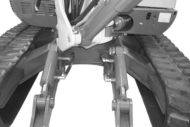
Offset cylinder check valve
The function of this valve is to clamp the offset cylinder hydraulically. The base and rod sides of the offset cylinder are under constant pressure; this maintains cylinder position. Applying pressure to one side of the cylinder supports this side, with additional pressure from the other side as the valve opens, in order to override the clamping pressure.
Note: The valve is located directly on the offset cylinder and can be accessed only by tilting the cab.
Shuttle valve block
• Rotation, boom swivel and dipper arm retraction must vent the gear motor's brake.
• High forces act on the brake and destroy it if it is not released during these operations.
Ref. Description
1 Port A (and record joystick (left) 4 and record main valve block, right-hand side rotation control)
2 Port B (and record joystick (left) 2 and record main valve block, left-hand side rotation control)
3 Port C (and record pedal, swivel 2 and record main valve block, offset cylinder extension control)
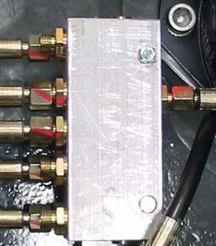
4 Port D (and record pedal, swivel 1 and record main valve block, offset cylinder retraction control)
5 Port E (and record joystick (left) 1 and record main valve block, dipper arm cylinder extension control)
6 Port F (and record gear motor SH, brake release)
Hydraulic system
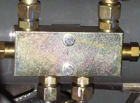
Changeover valve for SAE/ISO controls (option)
The directional valve is located on the left in base plate of the chassis (I), Fig 1.
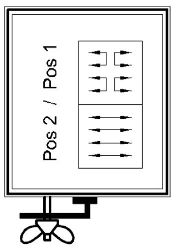
CAUTION!
Changing the directional valve overrides control lever operation. Make sure you know which control mode is selected before starting work. Always secure wing nut (J) on the directional valve’s changeover lever.
Switching from ISO to SAE controls and vice versa with the directional valve
Tighten wing nut (J) after changing control mode.
Directional valve ports
1Joystick (right) port 1
2Main valve block, boom cylinder retraction control
3Joystick (right) port 3
4Main valve block, boom cylinder extension control
5Main valve block, dipper arm cylinder extension control
6Joystick (left) port 1
7Main valve block, dipper arm cylinder retraction control
8Joystick (left) port 3
Ref.
1 Joystick (right) port 1
Description
2 Main valve block, boom cylinder retraction control
3 Joystick (right) port 3
4 Main valve block, boom cylinder extension control
5 Main valve block, dipper arm cylinder extension control
6 Joystick (left) port 1
7 Main valve block, dipper arm cylinder retraction control
8 Joystick (left) port 3