7 minute read
Operation


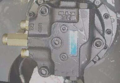
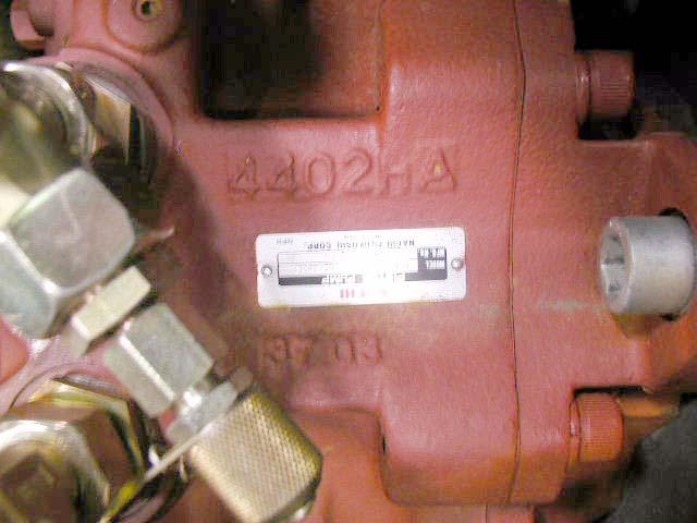
Hydraulic pump identification number
The hydraulic pump identification number is located on the hydraulic pump housing (Fig. 3).
Main valve block identification number
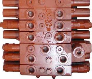
The main valve block identification number is located on the lower side of the main valve block (Fig. 4).
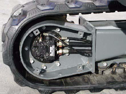
Travel drive identification number
Refer to Fig. 5 for the travel drive identification number location.
Swivel unit identification number
Refer to Fig. 6 for the swivel unit identification number location.
1.6Machine: overview
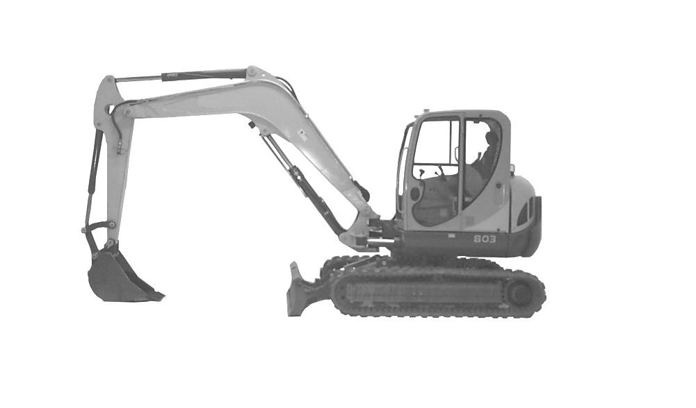
Dipper arm cylinder
Dipper arm
Operation controls
Boom
Operator’s seat
Hydraulic/fuel tank cover
Counterweight
Bucket
Engine cover cylinder
Boom cylinder Dozer blade
Bucket
Swing cylinder
Track frame
Swing frame/ superstructure
Travel drive motor
1.8Cab legend
Ref. Description
1Auxiliary hydraulics pedal cover
2Auxiliary hydraulics pedal
3Control lever (left)
4Control lever (right)
5Control lever base (left)
6Control lever base (right)
7Armrest (left)
8Armrest (right)
9Lever (horizontal seat adjustment)
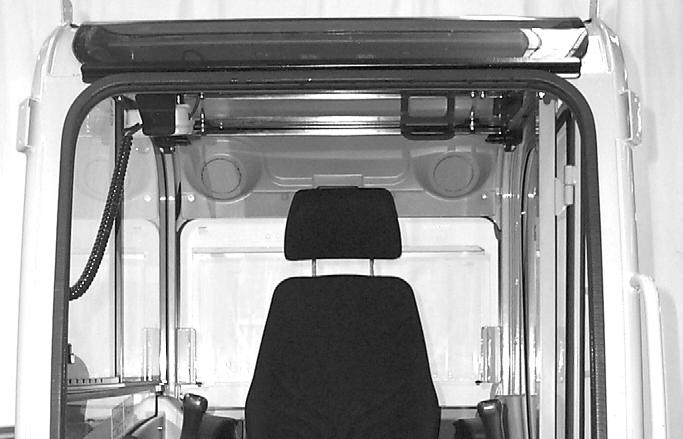
10Air vent (rear window, on the left)
11Air vent (rear window, on the right)
12Radio (option)
13Seat (back rest adjustment)
14Seat belt (lock)
15Cup holder
16Bracket (storage box for documents)
17Switch panel
18Throttle lever
19Fuse box
20Pre-heating/ignition switch
21Accessory power outlet
22Coolant temperature indicator
23Instrument cluster
24Drive pedal (left)
25Drive pedal (right)
26Drive lever (left)
27Drive lever (right)
28Dozer blade pedal/lever
1.10Instrument panel legend
Ref. Description
29 Hydraulic oil filter indicator (red) — Hydraulic oil filter indicator lamp comes on when hydraulic oil filter is dirty.
30 Air filter indicator (red) — Air filter indicator lamp comes on when air filter is dirty.
31
32
Battery charge indicator (red) — Battery charge indicator lamp comes on when the ignition is turned on and turns off as soon as the engine runs. The alternator or the charging circuit is faulty if the indicator lamp comes on with the engine running. The battery is no longer charged.
Engine oil pressure indicator (red) — Engine oil pressure lamp comes on when the ignition is turned on and turns off as soon as the engine runs. During normal operation, this indicator should remain off. The indicator will light if the engine oil pressure drops too low. If this occurs, shut off the engine IMMEDIATELY and determine the cause of the pressure drop.
33 Coolant temperature indicator (red) — Coolant temperature indicator lamp comes on when coolant temperature is too high.
34 Glow plug indicator (yellow) — Glow plug indicator lamp comes on when the ignition key is in the glow plug activation position. Indicator will go out when the glow plugs have heated sufficiently to start the engine.
35 Hour meter — Indicates the total operating hours of the machine. Use the hour meter to track maintenance in the maintenance log.
36 Fuel level gauge — The fuel level gauge shows the amount of fuel in the tank.
37 Indicator light — Not assigned.
38 Indicator light — Not assigned.
39 Hydraulic oil temperature indicator light — Hydraulic oil temperature indicator lamp comes on when hydraulic oil is too hot.
40 Coolant temperature gauge — Displays coolant temperature.
41 High-speed switch (transport speed) — Pressing the switch will enable high travel speed.
42 Windshield wiper switch (cab models only) — Pressing the two-position switch to the first position turns the windshield wiper on. Pressing and holding the switch in the second position activates the washer fluid pump.
43 Work light switch — Press switch to the ON position to turn on the boom work light.
44 Roof lights (option) — Press switch to the ON position to turn on the roof lights.
45 Rotating beacon (option) — Press switch to the ON position to turn on the rotating beacon.
46
Ventilation fan (two-speed) — Press the two-position switch to turn on the ventilation fan. The first position is the low fan speed position and the second position is the high fan speed position. If the Summer/Winter operation valve is in the OPEN or HEATING position, this switch will function as the cab heater ON/OFF switch. The Summer/Winter operation valve is located under the hood, on top of the engine, behind the radiator.
47 Air conditioning (option) — Press the switch to turn on the air conditioning. 48
Operation
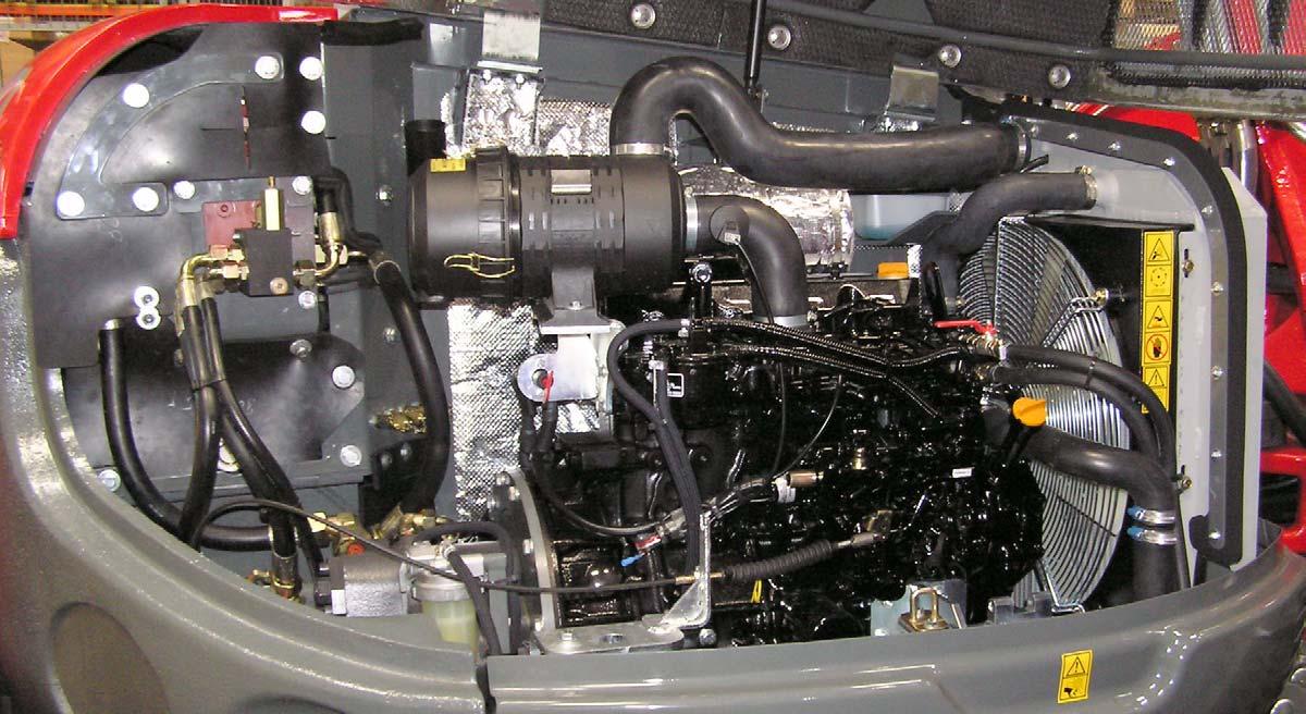
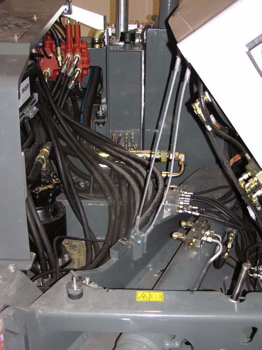
1.11Engine compartment: overview
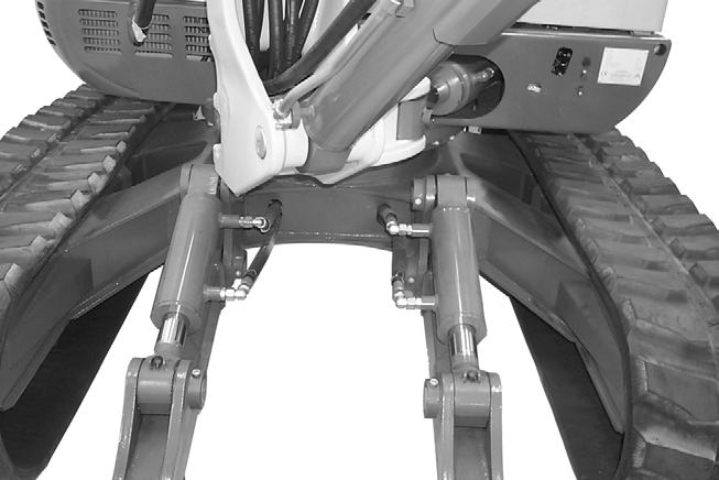
1.12Chassis: overview
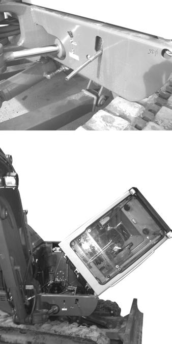
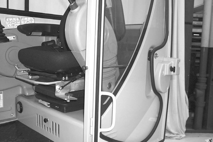
1.13Tilting the cab
WARNING!
Careful when tilting the cab — Risk of accidents.
Always tighten lock-down nuts (2 and 3) before driving or using the machine.
Always close the door.
Stay clear from underneath the cab as you tilt it:
•Turn off the engine.
•Remove the ignition key.
•Fold the control lever base (left) up.
Tilting the cab up
1.Follow “Mandatory Safety Shutdown Procedure” in the “Safety Instructions” in the Operator’s Manual.
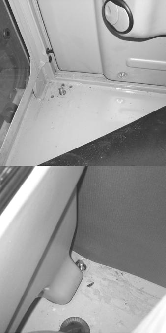
2.Raise the floor mat (1) at the right front of the cab and remove cab lock-down nut (2). Remove cab lock-down nut (3) at the right rear of the cab.
3.Securely close the cab door.
4.Locate the jack handle tubes (4) from the tool kit in the engine compartment. Insert them into the jack (5), and jack to the limit. The cab will be raised as far as the jack (5) will travel.
5.Pull handle (7) until the cab is completely tilted and supported by safety cables (8).
6.Remove the tilt rod (9) from the storage bracket (10). Slide the tilt rod (9) into the guide bracket (11) and secure with the split pin.
Tilting the cab down
1.Remove the tilt rod (9) from the guide bracket (11) by removing the split pin. Slide the tilt rod (10) out of the guide bracket (9) and secure with the split pin back in the storage bracket (10).
2.Use handle (7) to slowly lower the cab back onto the jack (5).
3.Remove jack handle tubes (4) from the jack (5) and insert the opposite end of the jack handle tubes (4) onto the release pin (6). Slowly turn release pin (6) counterclockwise until the cab is lowered.
4.Turn the release pin (6) clockwise.
5.Reinstall the cab lock-down nuts (2 and 3).
6.Place the jack handle tubes (4) back in the tool kit.
1.14SAE operating controls (standard)
WARNING!
•Always tighten cab lock-down nuts before driving or using the machine.
•Always close the cab door before tilting the cab.
•Stay clear from underneath the cab as it is tilted.
•Always secure the tilt rod in the support position when the cab is tilted.
SAE boom and bucket functions are controlled by the right and left-hand joystick control levers located on the seat consoles.
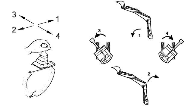
SAE left-hand joystick
1 — Arm extend
2 — Arm retract
3 — Swing left
4 — Swing right
SAE right-hand joystick
5 — Boom lower 6 — Boom raise
7 — Curl bucket in 8 — Curl bucket out
Note: The joystick controls are pilot-operated. The farther the controls are moved from center, the faster the machine will function.
1.15ISO operating controls (selectable)
ISO boom and bucket functions are controlled by the right- and left-hand joystick control levers located on the seat consoles.
ISO left-hand joystick
1 — Boom lower
2 — Boom raise
3 — Swing left
4 — Swing right
ISO right-hand joystick
5 — Arm extend
6 — Arm retract

7 — Curl bucket in
8 — Curl bucket out
Note: The joystick controls are proportional in operation: the farther the controls are moved from center, the faster the machine will function.
1.16Boom slew/auxiliary hydraulics pedal
The boom can be slewed, or swung, without moving the swing frame by pressing and holding the auxiliary hydraulic/changeover valve button (1) on top of the left-hand joystick, and then pressing the auxiliary hydraulics pedal (2) left or right. See Fig. 13.
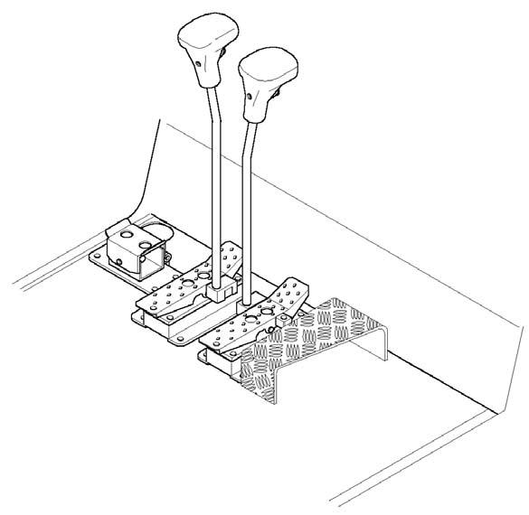

Pressing and holding the auxiliary hydraulic/changeover valve button (1) and pressing the auxiliary hydraulics pedal (2) to the left with your toe slews the boom to the left. Pressing and holding the auxiliary hydraulic/changeover valve button (1) and pressing the auxiliary hydraulics pedal (2) to the right with your toe slews the boom to the right.
The auxiliary hydraulics pedal (2) allows use/control of front-end attachments. Action will vary depending on the attachment and how it is connected.
1.17Dozer blade
The dozer blade is controlled by the dozer control pedal/lever (1) located next to the travel controls. See Fig. 14.

• Push control pedal/lever forward to lower the blade.
• Pull control pedal/lever rearward to raise the blade.
1.18Throttle lever
The engine RPM is controlled by the throttle lever (1) located next to the right-hand control console. See Fig. 15.
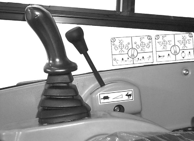
• Push throttle lever (1) forward to lower the engine RPM.
• Pull throttle lever (1) rearward to increase the engine RPM.
Operation
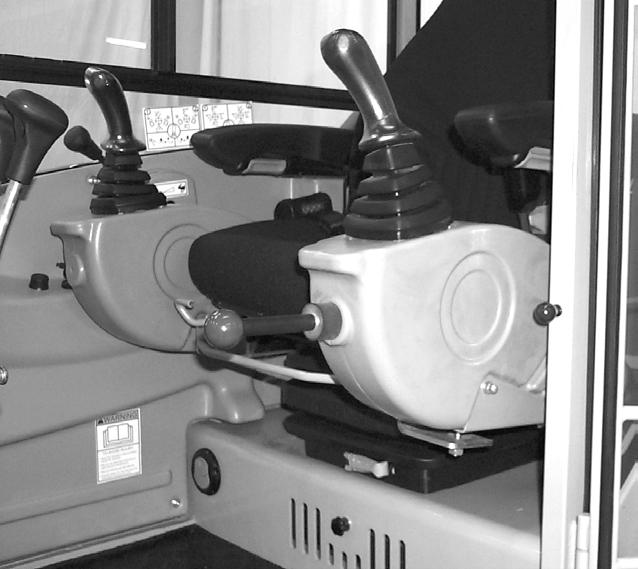
1.19Operator’s seat adjustments
Note: The operator’s seat left-hand console must be raised in order to exit the cab. In the lowered or work position, all operational functions are activated, and operator exit is blocked by the warning arm/lever. In the raised position, all the hydraulic functions of the machine are locked out.
1.Seat suspension adjustment:
Rotate the knob (1), to adjust the seat suspension for the operator’s weight. See Fig. 16. An indicator on the front of the seat base shows the weight adjustment in kilograms (1 kg = 2.2 lbs.) Adjust the seat suspension correctly to ensure a comfortable ride.
2.Horizontal seat adjustment:
The seat adjustment lever (2) allows the operator to move only the seat forward and rearward.
3.Horizontal seat and control adjustment:
The seat adjustment lever (3) allows the operator to move both the seat and the controls forward and rearward.
4.Armrest height adjustment:
The armrest height adjustment (4) allows the operator to raise or lower the armrests by turning the adjustment wheel. The rear of the left-hand armrest has a turnbuckle that may need to be adjusted to allow the left-hand armrest to rotate out of the way when the left-hand console is raised. Use the turnbuckle to adjust the armrest so it does not contact the left-hand control lever when raising the left-hand console to the lock-out position.
5.Backrest adjustment:
The backrest adjustment lever (5) allows the operator to move the backrest forward and rearward.
6.Headrest adjustment
The headrest adjustment (6) allows the operator to move the headrest up and down.
7.Seat height adjustment:
The seat height adjustment allows the operator to move the seat height up and down. To raise the seat height, grasp the seat and lift up until you hear an audible click. To lower the seat, raise the seat to the highest position and then lower the seat to its lowest position.