5 minute read
4Engine


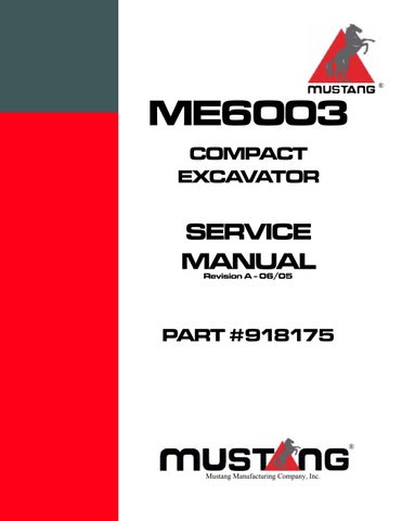
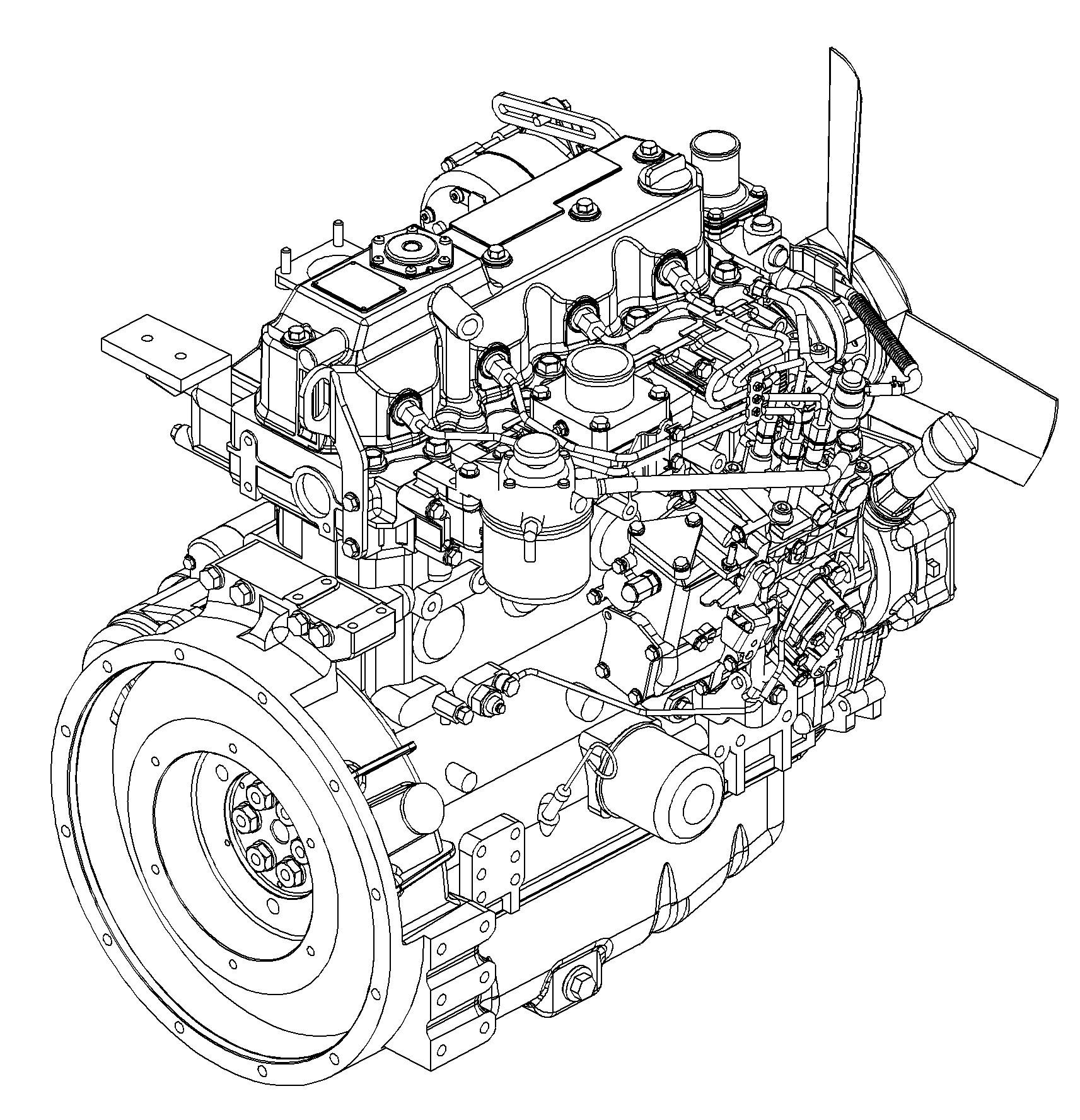
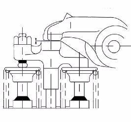
4.14TNV98 engine: overview
Oil pressure switch
Oil dipstick
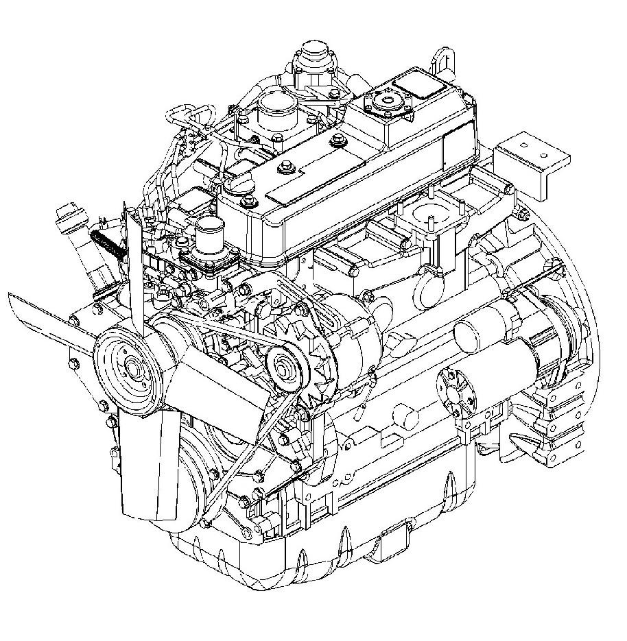
4.2Fuel system
4.3Removing the cylinder-head cover
Important!
The fuel injection lines run through the engine cylinder-head cover. Remove the cylinder-head cover with extreme care to avoid damaging the injector lines.
1.Remove all injection lines from the cylinder-head cover.
2.Carefully move the injection lines away from the engine.
3.Remove the rubber grommets from the cylinder-head cover with a screwdriver.
4.Remove the cylinder-head cover bolts and the cylinder-head cover. Remove the bolts according to the order shown in the following figure.
4.4Checking and adjust ing valve tip clearance
Important!
Stop the engine and allow it to cool before checking/adjusting valve tip clearance. Setting standard valve tip clearance is possible only on a cold engine.
1.Stop the engine and allow it to cool.
2.Remove the cylinder-head cover – See Section 4.3 Removing the cylinder-head cover on page 4-4.
3.Crank the engine until the cylinder is at the compression cycle top dead center.
4.Check the valve cap for abnormal wear.
5.Check valve tip clearance with a feeler gauge (see Fig. 4). Valve tip clearance should be 0.002 – 0.010 in. (0.15 – 0.25 mm).
6.Loosen locknut (C), Fig. 5 on the cylinder.
7.Adjust valve tip clearance by turning set screw to 0.002 – 0.010 in. (0.15 –0.25 mm).
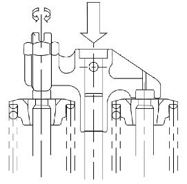
8.Tighten locknut (C).
9.Check the setting again with the feeler gauge.
10.Repeat the procedure for each cylinder
11.Position the cylinder-head cover gasket.
12.Replace and secure the cylinder-head cover – See Section 4.5 Cylinder head bolt tightening order on page 4-6.
4.5Cylinder head bo lt tightening order
☞ Tighten the cylinder-head bolts as follows:
➥ Tightening torque:
• 1st pass 36.1 – 43.4 lbf-ft (49,0 – 58,8 Nm)
• 2nd pass 76 – 83.3 lbf-ft (103,1 – 112,9 Nm)
Important!
Oil the bolt threads and the contact surfaces of the cylinder-head bolts before inserting them. Tighten the cylinder-head bolts according to the order showin in the following figure.
4.6Checking the injection nozzles
WARNING!
Keep hands away from the injector nozzle jet. Fuel exits the nozzle under extremely high pressure and can penetrate the skin and eyes. Escaping fuel under pressure can be invisible and can penetrate the skin and cause serious injury. If any fuel is injected into your skin, see a doctor immediately. Injected fluid MUST be surgically removed by a doctor familiar with this procedure or gangrene may result.
Pressure check
1.Remove the injection line and the injection nozzle.
2.Connect the injection nozzle to the high pressure line of the nozzle tester.
3.Slowly increase pressure until the nozzle ejects fuel and read the pressure indicated by the pressure gauge. Injection pressure should be 3191 – 3336 psi (220 – 230 bar).
4.If the injection pressure is too low, replace the spacer in the nozzle with a thicker one. If the pressure is too high, replace the spacer with a thinner one. See Fig. 8.
Note: Spacer thickness of 0.1 mm corresponds to a change in pressure of 276 psi (19 bar).
Pressure spring centring
Nozzle needle
Compression spring seat
Compression spring seat
Lower nozzle screw fitting
Nozzle body
4.7Checking the nozzle jet
WARNING!
Keep hands away from the injector nozzle jet. Fuel exits the nozzle under extremely high pressure and can penetrate the skin and eyes. Escaping fuel under pressure can be invisible and can penetrate the skin and cause serious injury. If any fuel is injected into your skin, see a doctor immediately. Injected fluid MUST be surgically removed by a doctor familiar with this procedure or gangrene may result.
1.Remove the injection lines and the injection nozzles.
2.Connect the injection nozzle to the high pressure line of the nozzle tester.
3.Quickly create pressure until the nozzle ejects fuel (ejection 3 – 4 times).
4.Hold a white sheet of paper about 12 in. (30 cm) away from the nozzle and let the nozzle eject fuel.
5.The nozzle jet must create a circle on the paper.
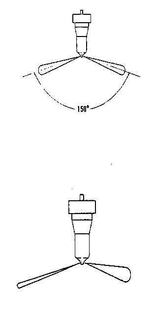
Normal atomization
6.Check the nozzle for drips after it has ejected fuel.
7.Create a pressure of about 290 psi (20 bar) below injection pressure and check whether fuel escapes from the nozzle.
Bad atomization
4.8Injection timing
1.Remove the injection line for the 1st cylinder. Note: Cylinder numbering always starts from the flywheel side.
2.Turn the engine clockwise (as seen from the radiator) by rotating the crankshaft until fuel escapes from the injection pump's base valve.
3.Remove the rubber cover from the flywheel housing and read injection time from the marks on the flywheel and flywheel housing.
4.If the marks do not coincide, adjust injection timing by turning the fuel injection pump.
➥ Injection too late: turn the pump away from the engine.
➥ Injection too early: turn the pump towards the engine.
Longitudinal slots for turning the pump
4.9Adjusting engine idle
Important!
Maximum engine speed is set at the factory and cannot be modified.
Note: Adjust engine idle without load.
1.Run the engine until it reaches operating temperature.
2.Check idling speed (A) and maximum engine speed (B) with all implement functions in neutral.
➥ Idling speed: 1050 +/- 50 rpm.
➥ Max. torque: 2575 +/- 50 rpm.
3.Adjust as required.
4.10Compression
1.Remove the injection lines and injection nozzles.
2.Remove the plug for the cut-off solenoid to set the fuel injection pump to zero delivery.
3.Crank the engine 2 - 3 revolutions. Note: Do not attempt to start the engine.
4.Mount the compression gauge on the cylinder you want to measure.
5.Crank the engine with the starter and read the pressure indicated by the pressure gauge.
➥ Specified value: 508 +/- 14.5 psi (35 +/- 1 bar) @ 250 rpm
➥ Limit value: 406 +/- 14.5 psi (28 +/- 1 bar) @ 250 rpm
4.11Checking the coolant thermostat
1.Remove the thermostat.
Housing cover
Thermostat
Seal
Housing
Thermal switch
Fig. 12:Coolant thermostat
Thermal switch
Thermal switch
2.Heat the thermostat in a container filled with water.
3.Using a thermometer, check whether the thermostat opens at 157 – 162.5 °F (69.5 – 72.5 °C).
4.12Checking the thermal switch
Thermometer
1.Remove the thermal switch.
2.Heat the thermal switch in a container filled with antifreeze or oil.
3.Using an ohmmeter, measure the resistance of the thermal switch as shown. The switch must allow the coolant to pass at a temperature of 224 – 236 °C (107 – 113 °C).
Test prods
Fig. 13:Checking the thermal switch
4.13Oil pressure switch
1.Remove the cable connection from the oil pressure switch (in the area of the cut-off solenoid).
2.Start the engine and check for correct idling speed.
3.Using an ohmmeter, measure the resistance of the oil pressure switch as shown.
➥ Infinite resistance indicates the oil pressure switch is OK.
➥ The oil pressure switch is defective if the oil can pass.
4.14Checking the coolant circuit
Coolant system leakage check:
1.Completely fill the radiator.
2.Mount an hand pump adapter on the radiator as shown.
3.Increase the pressure in the cooling circuit by means of a hand pump to about 34 psi (2.34 bar).
➥ Check the coolant circuit lines/connections for leaks if the pressure drops at the pressure gauge.
Radiator cap check:
1.Remove the radiator cap and mount it onto the pressure tester as shown.
2.Increase the pressure to about 34 psi (2.34 bar) (stamped onto the radiator cap) with the pressure tester.
➥ Radiator cap must open.