
25 minute read
3Maintenance


3.1General informat ion care and servicing WARNING!
•Instruction is necessary before operating or servicing the machine. Read and understand this entire manual. Follow warnings and instructions for operation and maintenance. Check for correct function after adjustments or maintenance. Failure to follow instructions can result in serious injury.
•Be sure you are familiar with all safety devices and controls before operating or servicing the machine. Know how to stop before starting. This machine is designed for use only with Mustang approved accessories or attachments. The Mustang Company cannot be responsible for safety if the unit is used with non-approved attachments.
•Hydraulic reservoir is under pressure. Avoid contact with leaking hydraulic fluid or diesel fuel under pressure. It can penetrate the skin and eyes.
Care and servicing
Care and servicing have a significant influence on the readiness for operation and service life of the machine.
Before performing service and maintenance, always read, understand and follow the instructions provided in:
•The "Safety Instructions" section in the operator’s manual.
•All associated attachment operator’s manuals.
For additional service information about the engine, see the engine manual provided with the machine.
Use of lubricants that do not correspond to the manufacturer’s recommendations may invalidate warranty claims.
More frequent servicing, other than the recommended intervals, may be required under extreme operational conditions (extremely dusty or hot conditions).
Always dispose of waste lubrication oils and hydraulic fluids according to local regulations or take to a recycling center for proper disposal. DO NOT pour fluids onto the ground or down a drain.
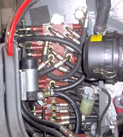
DO NOT power wash the main hydraulic pumps and controls, throttle solenoids and sealed bearings. High pressure water can be forced through seals and trapped within these components, causing premature failure.
The operating pressure settings of the hydraulic system should only be adjusted by trained, qualified personnel. If malfunctions are caused by unauthorized alteration of operating pressure settings, all warranty responsibilities of the manufacturer are invalidated.
Maintenance
Maintenance safety
•Never service the machine without reading the applicable instructions.
•Always lower bucket and dozer blade to the ground before performing any maintenance.
•Use correct procedures to lift and support the machine. Always lift the blade fully before installing jackstands.
•Keep engine cover and hydraulic valve cover closed except for service. Close and latch covers before operating the machine.
•Be sure to have the work area properly ventilated when grinding or welding parts. Wear a dust mask.
•Exhaust fumes can kill. Exhaust system must be tightly sealed. If working in an enclosed area, vent exhaust to outside when engine must be run for service.
•Never modify equipment or add attachments not approved by the Mustang Company
•Stop the engine and let it cool, then clean engine of any flammable materials before checking fluid levels.
•Never service or adjust machine with the engine running unless the service procedure requires it.
•Avoid contact with leaking hydraulic fluid or diesel fuel under pressure. It can penetrate the skin and eyes. NEVER use your hands to search for hydraulic fluid leaks; use a piece of paper or cardboard. Escaping fluid under pressure can be invisible and can penetrate the skin and cause serious injury. If any fluid is injected into your skin, see a doctor immediately. Injected fluid MUST be surgically removed by a doctor familiar with this procedure or gangrene may result.
•Never fill fuel tank with engine running, while smoking or when near open flame.
•Keep body, jewelry and clothing away from moving parts, electrical contacts, hot parts and exhaust.
•Wear eye protection when servicing the machine.
•Lead acid batteries produce flammable and explosive gas. Keep arcs, sparks, flames and lighted tobacco away from batteries.
•Batteries contain acid which burns eyes and skin on contact. Wear protective clothing. If acid contacts body, flush well with water. For eye contact, flush well with water and get immediate medical attention.
3.2Maintenance decal symbols
Symbol Assembly Explanation
General Visual check
General Grease instructions
Fuel system Drain condensation water
Fuel system Replace the fuel filter, clean the fuel pre-filter
Radiator Check the coolant level
Radiator Replace coolant
Engine Check valve tip clearance; adjust if necessary
Engine Check the engine oil level
Engine Replace engine oil
Engine Replace the oil filter
Engine Check V-belt tension
Travelling drive Change oil
Travelling drive Check oil
Undercarriage Check track tension
Hydraulic system Check oil level
Hydraulic system Change hydraulic oil
Hydraulic system Replace the hydraulic oil filter, replace the breather filter
3.3Maintenance decal
3.4Maintenance schedule
Check,
Maintenance
Fluid and filter changes
Engine oilx*xx
Engine oil filterx*xx
Fuel filterx*xx
Air filter element when indicator light comes onx
Engine coolant xx
Hydraulic oil filter insertx*xx
Hydraulic oilxx
Breather-hydraulic oil tankxx
Gearbox oilx*xx
*1st engine oil change only
Air conditioning
Test air conditioning functionxxx
Replace cab air filterxx
Check dehumidifier for corrosionxx
Replace dehumidifierxxx
Replace compressor oilxxxx
Functional check
Lights, signaling system, audible warning system xx
Air cleaner dust valvex
Heating functionxxx
Leakage check
Engine and hydraulic system componentsxx
Cooling and heating circuit componentsx x
Traveling drive componentsx x
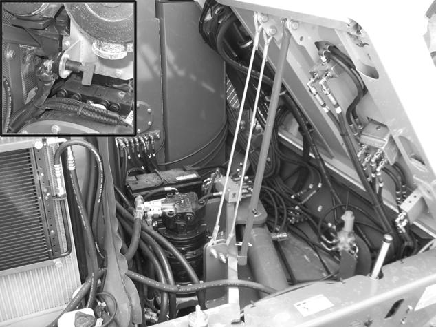
Lubrication (see Fig. 2)
3.5General Maintenance
Cleaning
Cleaning the machine is divided into three separate areas:
• Cab interior
• Machine exterior
• Engine compartment
For safety and health reasons, follow the following cleaning instructions:
Washing solvents
• Ensure adequate room ventilation.
• Wear suitable protective clothing.
• Do not use flammable liquids, such as gasoline or diesel fuel.
Compressed air
• Work carefully.
• Wear goggles and protective clothing.
• Do not aim the compressed air at the skin or at other people.
• Do not use compressed air for cleaning your clothing.
When using a high-pressure cleaner or steam jet
• Electric components and damping material must be covered and not directly exposed to the jet.
• Before use, cover the vent filter on the hydraulic oil tank and the filler caps for fuel, hydraulic oil, etc.
• Additionally, protect the following components from moisture:
• Engine.
• Electric components such as the alternator, etc.
• Control devices and seals.
• Air intake filters, etc.
When using volatile and easily flammable anti-corrosion agents and sprays:
• Ensure adequate room ventilation.
• Do not use unprotected lights or open flames.
• Do not smoke!
Maintenance
Cab interior
Exterior of the machine
Engine compartment
CAUTION!
Never use high-pressure cleaners, steam jets or high-pressure water to clean inside the cab. Water under high pressure may penetrate into the electric systems, cause short circuit, damage seals, and disable controls.
The following items are recommended for cleaning the cab interior:
• Broom
• Vacuum cleaner
• Damp cloth
• Bristle brush
• Water and mild soap solution
Cleaning the seat belt:
• Clean the seat belt with only a mild soap solution; do not use chemical agents because they may destroy the seatbelt fabric.
The following items are suitable for cleaning the cab exterior:
• High-pressure cleaner
• Steam jet
Important!
Switch off the engine and allow it to cool before spraying the machine with a high-pressure cleaner or steam jet.
Important!
When cleaning the engine with a water or steam jet, do not point the jet directly at electric sensors such as the oil pressure switch. Humidity penetrating electric sensors will cause them to fail and lead to engine damage.
Screw connections, attachments, pivots and hinges
Screw connections and attachments
All screw connections must be checked regularly for tightness, even those not listed in the maintenance schedules. Tighten loose connections immediately.
Pivots and hinges
All mechanical pivot points on the machine (e.g., door hinges, joints) and fittings (e.g., door arresters) must be lubricated regularly.
Maintenance
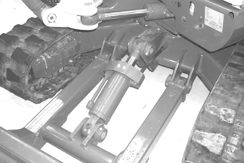
Lubrication strip
Apply grease to the lubrication strip as follows:
1.Lubrication point (A) for the offset cylinder
2.Lubrication point (B) for the live ring
Important!
Apply grease to lubrication points A and B daily.
A portable lamp can be connected to the lubrication strip's 12 V connection C
Important!
See Fluids and lubricants on page 3-23 for lubricant specifications.
3.7Engine
Important!
Be sure to read the engine manual supplied with the machine.
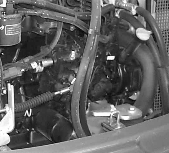
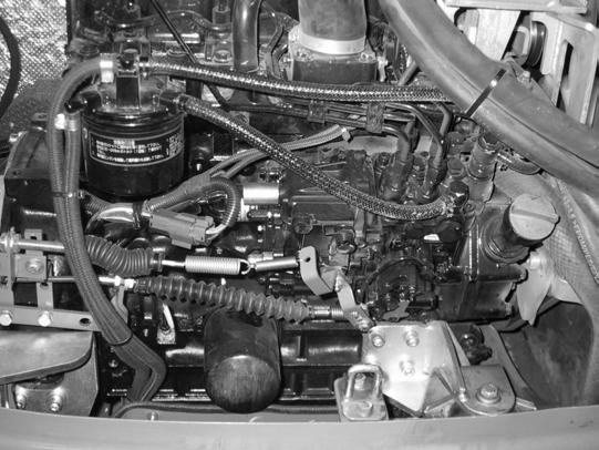
Checking engine oil level
Important!
See Fluids and lubricants on page 3-23 for engine oil grade. Only use engine oil specified, or equivalent quality and grade, or damage to the engine could occur.
To check the engine oil, the machine must be on a level surface and the engine turned off.
1.Run the engine until it reaches operating temperature, then stop the engine.
2.Pull the engine cover latch lever (located beneath the operator’s seat) and raise the engine cover.
3.Check the engine oil level using the dipstick (1) located at front of the engine. See Fig. 4.
4.Add oil if required through the oil filler neck (3). See Fig. 4.
Note: The marks on the dipstick indicate the minimum and maximum oil levels.
3.8Changing engine oil and filter
1.Place the machine on a level surface. Run the engine until it is at operating temperature, then turn off the engine.
2.Pull the engine cover latch handle (located beneath the operator’s seat) and raise the engine cover.
3.Position waste oil collection container under engine oil pan.
4.Remove the drain plug from the oil pan and allow oil to drain into waste oil collection container.
5.Remove the oil filter, using a filter wrench as necessary. See (2) Fig. 4.
6.Clean the filter housing surface. Put a film of clean oil on the filter gasket. Install the new filter with gasket and hand tighten.
7.Reinstall the drain plug.
8.Remove the oil fill cap from the engine. Pour in new oil. Crankcase capacity (including the oil filter) is 8.2 qts. (7.8 L). DO NOT fill crankcase above the MAX mark on the dipstick.
9.Reinstall oil filler cap.
10.Start the engine and let it run for several minutes. Watch the engine oil light on the control panel. The light should turn off after several seconds. If it does not, shut off engine and determine cause.
11.Stop the engine and check for leaks at the oil filter and oil drain plug.
12.Check the oil level again and add oil if necessary.
3.9Air cleaner service
Note: The air filter indicator light illuminates when the air cleaner element needs to be replaced. See Instrument panel, switches and indicators on page 1-8
Important!
Filter cartridges degrade prematurely when used in acidic air. Acidic air is present in acid production facilities, steel and aluminium mills, chemical plants and other non-ferrous metal plants.
Do not clean air filter cartridges, replace them instead. never reuse a damaged air filter.
General air filter maintenance:
•Store filters in original packaging in a dry place.
•Do not strike the filter against other objects during installation.
•Check air cleaner attachments, air intake hoses and air filters for damage. Repair or replace as necessary.
•Frequently check clamps and screws at the induction manifold for tightness. Tighten as necessary.
•Check the function of the dust valve weekly. Replace if necessary. See Dust valve functional check on page 3-13
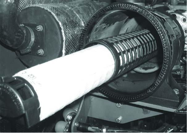
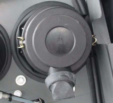
1.The air cleaner is located under the engine cover. Press the engine cover release button and raise the engine cover.
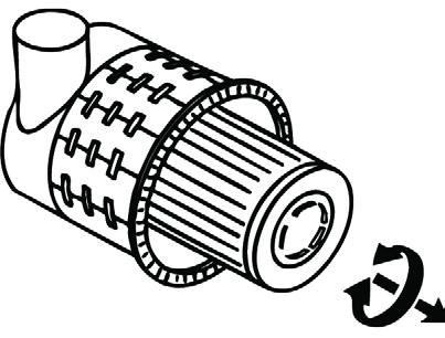
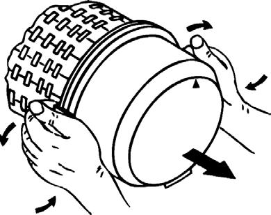
2.Release the bow clips (1) to remove the air cleaner cover and gasket (2). See Fig. 5.
3.Carefully remove outer air cleaner element (3). See Fig. 5. Carefully remove inner air cleaner element (3). Clean air cleaner elements with 30 psi (200 kPa) compressed air from the inside. Clean all contamination (dust) from inside the upper and lower air cleaner housing and cover.
4.Replace both the inner and outer air cleaner elements when the indicator light comes on or according to the maintenance schedule.
5.Reinstall air cleaner elements (3, 4), gasket and air cleaner cover (2). Fasten bow clips (1).
6.Close and secure engine cover.
Important!
Do not knock the air filter element against a solid object to remove dust. The element may become distorted and damaged.
Do not operate engine without the air cleaner element installed or damage to the engine could occur.
Dust valve functional check
Perform this check weekly.
1.Switch off the engine and allow it to cool.
2.Set the parking brake.
3.Squeeze the discharge slot of dust valve (B), Figure Fig. 6.
3.10Fuel system
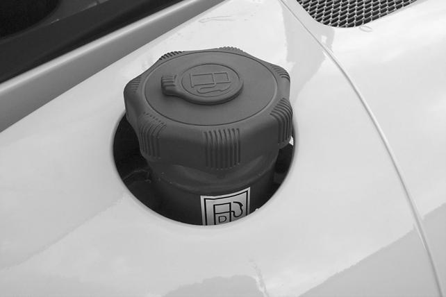
Filling the fuel tank
WARNING!
Stop and cool the engine before adding fuel. NO SMOKING! Failure to this instruction can cause an explosion or fire.
The fuel level in the tank is indicated by the fuel gauge (1) on the console. See Fig. 7.
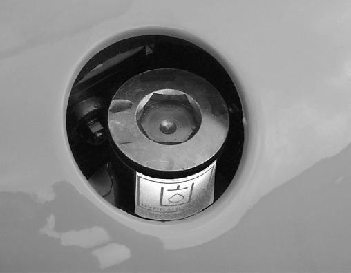
To fill the tank, remove the fuel filler cap (2) located on the left rear of the unit behind the cab by rotating the lock cover (3) and inserting the ignition key into the lock and unlocking the cap. See Fig. 7. Fill using clean diesel fuel with a cetane rating over 45. Re-install fuel cap.
Important!
Never operate machine until fuel tank is completely empty. If this occurs, the fuel system will have to be bled of air. Always fill tank after use.
When using the machine in cold weather, make sure to use the proper fuel blend to prevent the fuel filters from “jelling” up. If this happens, the fuel filter and water separator elements will have to be replaced, and the fuel will have to be replaced with the proper fuel.
WARNING!
Always clean up spilled fuel and oil. Keep heat, flames and sparks away from fuel and oil. Failure to use care around combustibles can cause explosion or fire, which can result in injury or death.
Fuel filter
The fuel filter is located behind and below the engine cover.
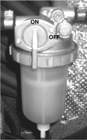
1.Shut off fuel using the shut-off valve (2) on the water separator. See Figure Fig. 9.
2.Clean dirt from the housing and unscrew the fuel filter element. See FigureFig. 8.
3.Remove and discard old filter element properly.
4.Clean around the filter housing.
5.Put oil on the seal of the new filter element.
6.Install the fuel filter and hand tighten.
7.Open fuel valve.
The fuel system must be purged of air after changing the fuel filter, or if the fuel tank has been run dry – see Purging air from the fuel system on page 3-15.
Fuel shut-off valve, fuel pre-filter and water separator
If water is seen in the plastic water separator bowl or the indicator ring rises to position (3), the bowl will need to be drained. See Fig. 9.
Note: The water separator is located behind the engine underneath the engine cover.
1.Shut off fuel using the fuel valve (2). See Fig. 9.
2.Unscrew plug (4) and collect the water that drains out of the hose. Allow water to drain until the indicator ring returns to the bottom of the water separator.
3.Tighten plug (4) and discard fuel/water according to local regulations. DO NOT pour it onto the ground or down a drain.
4.Open fuel valve.
Purging air from the fuel system
WARNING!
DO NOT air bleed a hot engine. Spilled fuel can cause a fire.
The fuel system runs from the fuel tank, through the water separator, fuel filter, fuel injection pump and high pressure piping to the fuel injection nozzles. If the fuel tank has been run dry, or if the fuel filter, water separator or fuel lines have been replaced, trapped air will have to be removed, or bled, from the fuel system. Bleed air from the fuel system according to the following steps:
1.Fill the fuel tank.
2.Make sure that the valve on the water separator valve (2) is in the “ON” position.
3.Turn the ignition key to the first position.
4.Wait about five minutes while the fuel system bleeds itself automatically.
5.Start the engine.
3.11Coolant system
If the engine runs smoothly and then stops, or if it does not run smoothly, switch off the engine and bleed the system again as described above.
Checking coolant level
Important!
Insufficient coolant level reduces heat dissipation capacity which can lead to engine damage.
Note: Engine must be cold.
1.Pull the engine cover latch handle (located beneath the operator’s seat) and raise the engine cover.
2.Check the coolant level in the expansion reservoir. See Fig. 10.
3.If low, remove cap and overflow tube.
4.Fill reservoir to FULL line (1). Refer to the engine manual for correct coolant mixture for the engine.
3.12Electrical system
WARNING!
Disconnect the negative battery terminal before working on the electrical system.
Fuses
The fuse panel is located on the right-hand console, towards the rear, below the switches. See (1), Fig. 11.
To replace a fuse, remove the panel cover and pull the old fuse from the socket. Install a new fuse of the same rating and re-install the fuse panel cover.
Important!
Determine what caused the fuse to blow and repair the defect.
See Electrical system on page 2-4 in the Specifications chapter for fuse identification.
Battery
WARNING!
•Batteries contain acid, which burns eyes and skin on contact. Wear safety goggles and protective clothing to keep acid off body.
•If battery acid is spilled, thoroughly rinse the affected surfaces immediately with plenty of water.
•Keep open flames and sparks away from the battery. Battery operation produces flammable/explosive gas.
•Do not interrupt the battery jump charging circuit at the battery terminals. Sparking may result.
•Do not jump start the machine if the battery is frozen or battery electrolyte level is low. An explosion or ruptured battery may result.
•Make sure the poles (+/-) are not reversed when jumping the battery.
•Never place tools/conductive items on the battery. A short circuit may result.
In case of acid contact, wash immediately with water for several minutes. In case of eye contact, get medical attention immediately.
The battery is located under the cab near the rear of the undercarriage. See (1) Fig. 12.
To access the battery (1), see Tilting the cab on page 1-13 to tilt and secure the cab to gain access to the battery (2).
Battery cables must be clean and tightly secured. Remove any acid or corrosion from the battery and cables using a sodi um bicarbonate and water solution. Cover the battery terminals and cable ends with battery-saver grease. Note: The battery is maintenance-free and requires no other service.
Using a booster battery (jump-starting)
WARNING!
Keep arcs, sparks, and open flames away from batteries. When jump-starting from a booster battery, make the final connection (negative) to the machine frame away from the battery. A operating battery can create flammable gases. Sparks or open flames can cause this gas, and the battery, to explode.
DO NOT jump-start or charge a frozen battery. Warm battery to 60°F (16°C) before connecting to a charger. Unplug charger before connecting or disconnecting cables to battery.
Important!
Do not jump start using a running machine. High voltage spikes from a running machine can burn out glow plugs.
Important!
Damage to the alternator can occur if:
•Engine is operated with battery cables disconnected.
•Battery cables are connected when using a fast charger or when welding on the machine. When welding on the machine, remove both cables from the battery and ground the welder to machine frame near repair area.
•Incorrectly connected booster cables.
1.Be very careful when jump starting the machine. Booster battery must be 12volt.
2.Turn ignition key to the “OFF” position.
3.Open the engine cover.
4.First, connect one end of the cable to the positive (+) terminal on the booster battery. Connect the other end of the same cable to the positive (+) terminal on the battery disconnect switch (3), on the machine you are trying to start. See Fig. 12.
5.Connect one end of the second cable to the negative (-) terminal on the booster battery. Connect the other end of that same cable to the frame of the machine you are trying to start.
6.Start the engine. After the engine is running, remove the cable connected to the frame first. Disconnect the other cable from the battery disconnect switch (3) on the positive (+) terminal. See Fig. 12.
Alternator
Important!
DO NOT allow the cable ends to touch when removing them from the batteries. Arcs and direct short circuits can cause severe damage to the electrical system of a running machine.
Important!
Do not test run the engine with a disconnected battery.
Replace a defective alternator immediately. An illuminated battery charge Indicator can indicate a malfunctioning alternator. See "Battery Charge Indicator" in Instrument panel, switches and indicators on page 1-8
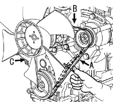
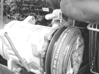
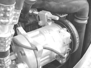
3.13Checking & adjusting V-belt tension
1.Switch off engine and fold up the control lever base.
2.Open the engine cover and carefully inspect the V-belt (1) for damage. If it is damaged, replace it.
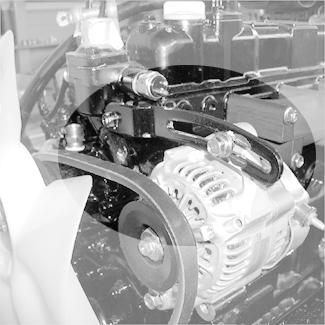
3.Press on the V-belt to check deflection. The belt deflection should be no more than 13/32” (10 mm). See Fig. 13. If deflection is more than 13/32” (10 mm), proceed to step 4.
4.Loosen adjustment bolt (2) and rotate the alternator (3) in the direction of the arrow until correct V-belt tension is established.
5.Tighten adjustment bolt (2) and re-check V-belt tension.
Checking & adjusting air conditioning V-belt tension
1.Switch off engine and fold up the control lever base.
2.Open the engine cover and carefully inspect the V-belt (1) for damage. If the V-belt (1) is damaged, replace it.
Maintenance
3.Press on the V-belt to check deflection. The belt deflection should be no more than 11/32” (9 mm). See Fig. 14. If deflection is more than 11/32” (9 mm), proceed to step 4.
4.Loosen jam nut (2) and rotate the adjustment nut (3) until the correct V-belt tension is established.
5.Tighten jam nut (2) and re-check V-belt tension.
Track system
Changing final drive oil
1.Position the machine on a level surface with final drive plugs positioned as shown in “Drain Position,” Fig. 15. Turn off the engine.
2.Open both plugs and drain oil into a suitable container. Re-install plugs.
3.Start the engine and move the machine slightly until plugs are positioned as shown in “Fill Position,” Fig. 15. Turn off the engine.
4.Remove both screw plugs. Pour fresh oil (Chevron Delo Gear 80W90 or BP Transgear 80W90) into the top hole until oil starts to run out of the bottom hole.
5.Re-install both plugs securely.
Environment!
Always dispose of oil according to environmental laws or take to a recycling center for proper disposal. DO NOT pour fluids onto the ground or down a drain.
Checking and adjusting track tension
1.Position the machine on a level surface with mark (B), Fig. 16 of the track positioned between drive pinion (C) and the track tension roller (D).
2.Use the bucket and dozer blade to lift the machine up until tracks are just clear of the ground as shown in Fig. 17. Turn off the engine.
3.Measure the clearance at the second track roller from the drive gear. Deflection should be between 3/4”-1” (20-25 mm).
4.Using a grease gun, pump grease into the fitting until the track is properly tensioned.
Note: A grease gun is supplied with machine tool kit.
Important!
Do not over-tension the track. If track is too tight, loosen the grease fitting to relieve pressure.
WARNING!
Do not loosen the track tensioner grease fitting more than two turns, or grease fitting could be ejected under pressure and cause injury.
5.Repeat steps 4 and 5 for the track on the other side.
6.Start the engine. Lower the unit to the ground.
3.14Fluids and lubricants
Diesel engine
Engine oil
Final drive unit
Gearbox oil2
SAE 10W30 or 15W40 API classification CD (or higher, e.g., CH-4), such as BP Vanellus MG 15w40, BP Vanellus C-Extra 10W30, or Chevron Delo 400 15W40.
EP Grade conforming to API GL5, such as Chevron Delo Gear 80W90 or BP Transgear 80W90.
ISO Viscosity Grade 46, with antiwear, anti-form and anti-oxidation additives, such as Mobil DTE 15M, Amoco Rykon 46, or BP Energol HLP-HD46.
Hydraulic oil tank
Hydraulic oil
Swing gear unit
Gear oil
Swing ring
Grease zerks
Heavy-duty lithium grease
Year-round About 1.4 qts. (1.3 L) each
Year-round
Mobil Delvac 1; Mobil EAL Envirosyn 68H -4—104°F (-20—40°C)
Mobil Delvac 1300 Super 10W30, XD-3 Elite 10W-30, XD-3 10W-30 14—104°F (-10—40°C)
Mobil Delvac 1300 Super 15W40, XD-3 Elite 15W-40, XD-3 15W-40 32—104°F (0—40°C)
API GL5 EP Grade, such as Chevron Delo gear 80W90 or BP Transgear 80W90 is required.
Heavy-duty 3% molybdenum disulfide lithium complex grease, such as Chevron RPM Heavy Duty Grease No. 2, Mobilgrease Moly 52 or BP Energrease Moly EP2.
Roller and friction bearings3 FINA Entergrease L21M; Mobil CMP
Open gear (live ring gears)
Multipurpose grease3
Entergrease MP-MG2
CMP
84.5 qts. (80 L)
Year-round As required
Year-round As required
Year-round 26 oz. (750 g) Compressor oil Sanden SP10 Year-round 4 oz. (116.5 cm³) Washer system Cleaning agent Water + antifreeze Year-round 2.1 qts. (2.0 L)
1.The capacities indicated are approximated values; the oil level check alone is relevant for the correct oil level
2.Hypoid gearbox oil based on basic mineral oil (SAE85W-90 according to DIN 51502), (API GL-4, GL5)
Maintenance
3.15Pressure check
General
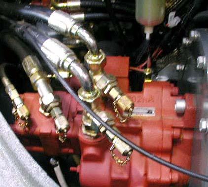
Pressure check of variable displacement pump P1
• Run the machine until it reaches normal operating temperature before checking hydraulic pressure.
Note: Hydraulic oil normal operating temperature: 122°F (50°C) minimum.
• Check pressure drop under a constant load.
• Set the primary pressure limiting valves (PPLV) with the engine at full throttle. See Hydraulic system on page 2-3 for the pressure settings.
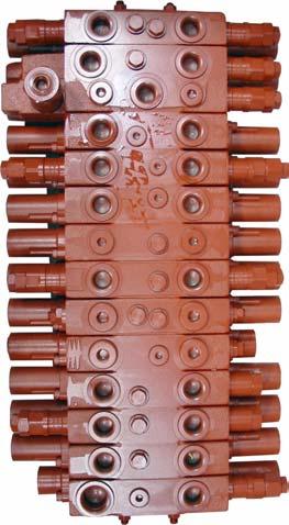
Hydraulic supply for boom, bucket and left-hand side drive functions.

Checking primary pressure limiting valve 1 (PPLV 1)
1.Connect a pressure gauge to measuring port MP 1 (1) Fig. 18.
2.With the engine at full throttle, extend the boom cylinder as far as it will go.
3.Check and record the pressure value.
Checking pressure prop
1.At full throttle, extend the boom cylinder as far as it will go.
2.Quickly reduce engine speed from maximum to minimum. Observe the pressure drop.
3.Check and record the pressure value.
➥ Pressure drop should not exceed the specified value by more than 10% (See Hydraulic system on page 2-3 for pressure values).
Adjusting primary pressure limiting valve 1 (PPLV 1) a.Loosen the pressure limiting valve locknut. b.Loosen the pressure limiting valve until you observe a pressure drop on the pressure gauge. c.Adjust the pressure limiting valve and tighten the locknut.
1.Adjust the pressure at the primary pressure limiting valve (PPLV 1) (A) Fig. 19 on the main valve block.
➥ The valve seat may be stuck and must be loosened first.
2.After completing the adjustment, check the primary pressure limiting valve 1 and the pressure drop.
3.Check the retract boom, the extend/retract bucket, and the left-hand side forward/reverse drive functions.
Pressure check of variable displacement pump P2
Hydraulic supply for dipper arm, right-hand side drive and auxiliary hydraulics functions.
Checking primary pressure limiting valve 2 (PPLV 2)
1.Connect a pressure gauge to measuring port MP 2 (2), Fig. 20.
2.With the engine at full throttle, extend the dipper arm cylinder as far as it will go.
3.Check and record the pressure value.
Checking pressure drop
1.With the engine at full throttl, extend the dipper arm cylinder as far as it will go.
2.Quickly reduce engine speed from maximum to minimum. Observe the pressure drop.
3.Check and record the pressure value.
➥ Pressure drop should not exceed the by more than 10%. (See Hydraulic system on page 2-3 for pressure values).
Adjusting primary pressure limiting valve 2 (PPLV 2) a.Loosen the pressure limiting valve locknut. b.Loosen the pressure limiting valve until you observe a pressure drop on the pressure gauge. c.Adjust the pressure limiting valve and tighten the locknut.
1.Adjust the pressure at the primary pressure limiting valve (PPLV 2) (B), Fig. 21, on the main valve block.
➥ The valve seat may be stuck and must be loosened first.
2.After the adjustment is complete, check the primary pressure limiting valve 2 and the pressure drop.
3.Check the dipper arm retraction and the right-hand side forward/reverse drive functions.
Checking the gear pump P3 pressure
Checking the auxiliary hydraulics pressure
Important!
Factory settings for auxiliary hydraulics secondary valves are possibly incorrect since the valves must be adapted to the implement.
Hydraulic supply for the dozer blade, auxiliary hydraulics/boom swivel and rotate functions hydraulic supply.
Checking primary pressure limiting valve 3 (PPLV 3)
1.Connect a pressure gauge to measuring port MP 3 (3), Fig. 22.
2.With the engine at full throttle, extend the dozer blade cylinder as far as it will go.
3.Check and record the pressure value.
Checking pressure drop
1.With the engine at full throttle, extend the dozer blade cylinder as far as it will go.
2.Quickly reduce engine speed from maximum to minimum. Observe the pressure drop.
3.Check and record the pressure value.
➥ Pressure drop should not exceed the specified value by more than 10% (See Hydraulic system on page 2-3 for pressure values).
Adjusting primary pressure limiting valve 3 (PPLV 3) a.Loosen the pressure limiting valve locknut. b.Loosen the pressure limiting valve until you observe a pressure drop on the pressure gauge. c.Adjust the pressure limiting valve and tighten the locknut.
1.Adjust the pressure at the primary pressure limiting valve (PPLV 3) on the main valve block (C), Fig. 23.
➥ The valve seat may be stuck and must be loosened first.
2.After the adjustment is complete, check the primary pressure limiting valve 3 and the pressure drop.
3.Check the following functions: retract dozer blade, boom swivel and rotate.
Checking pilot control pressure
Checking the auxiliary hydraulics pressure
Important!
Factory settings for auxiliary hydraulics secondary valves are possibly incorrect since the valves must be adapted to the implement.
Checking pilot control pressure
1.Connect a pressure gauge to measuring port MP (4), Fig. 24.
2.Move the control lever base (safety switch) to the work position.
3.Acuate the joystick.
4.Check and record the pressure value.
Adjusting pressure reducing valve 4 (PRV 4)
1.Adjust the pressure at the pressure reducing valve 4 (PRV 4) at the control oil unit (D), Fig. 25. (See Hydraulic system on page 2-3 for pressure values)
2.Check the pilot control pressure again after adjustment is complete.
Maintenance
Gear motor secondary pressure limiting valve
Check
1.Connect a pressure gauge to measuring port MP 4.
2.Place the bucket, the boom, or the dozer blade firmly against the ground to prevent the machine from moving when the travel drive is engaged. Engage the travel drive, which will push against the bucket/boom/dozer blade resistance and will build up pressure in the system.
3.Check and record the pressure value.
Adjusting the gear motor secondary pressure limiting valve a.Loosen the locknut of the pressure limiting valve. b.Unscrew the pressure limiting valve until you observe a pressure drop on the pressure gauge. c.Adjust the pressure limiting valve and tighten the locknut.
1.Adjust the pressure at the secondary pressure limiting valve on the gear motor.
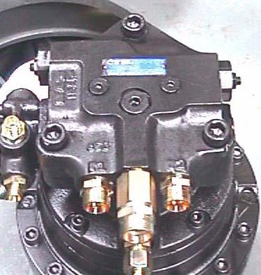
➥ The valve seat may be stuck and must be loosened first.
2.After the adjustment is complete, check the secondary pressure limiting valve again.
3.16Test report
Rated value 3553 ±44 psi (245 ±3 bar)
Drop 363 psi (25 bar)
Rated value 3553 ±44 psi (245 ±3 bar)
DOWN
EXTEND
Bucket
RETRACT
Left-hand side drive
FORWARD
REVERSE
Drop 363 psi (25 bar)
Rated value 3553 ±44 psi (245 ±3 bar)
Drop 363 psi (25 bar)
Rated value 3553 ±44 psi (245 ±3 bar)
Drop 363 psi (25 bar)
Rated value 3553 ±44 psi (245 ±3 bar)
Drop 363 psi (25 bar)
Rated value 3553 ±44 psi (245 ±3 bar)
Drop 25 bar
Auxiliary hydraulics
LEFT
Boom swivel
Rated
Drop 363 psi (25 bar)
Rated
Drop 363 psi (25 bar)
Rated value 3480 ±44 psi (240 ±3 bar)
Drop 363 psi (25 bar)
Rated value 3480 ±44 psi (240 ±3 bar)
Drop 363 psi (25 bar)
Rated value 3480 ±44 psi (240 ±3 bar)
Drop 363 psi (25 bar) RIGHT
Rated value 3480 ±44 psi (240 ±3 bar)
Drop 363 psi (25 bar)
3.17Hydraulic system
General hydraulic system service information
WARNING!
The hydraulic reservoir is under pressure. Never use your hands to search for hydraulic fluid leaks; use a piece of paper or cardboard to find leaks. Escaping fluid under pressure can be invisible and can penetrate the skin, causing serious injury. If any fluid is injected into your skin, see a doctor immediately. Injected fluid MUST be surgically removed by a doctor familiar with this procedure, or gangrene may result.
Hydraulic fluid flowing out of high pressure line may cause fire, malfunction, property damage and/or personal injury. If a hydraulic leak is detected, immediately shut down the machine and repair the leak before restarting the machine.
WARNING!
Insufficient, incorrect or contaminated hydraulic oil can damage the hydraulic system. Use a strainer/reflux when filling the system. Check the hydraulic oil level frequently and fill as necessary. See Checking hydraulic oil level on page 3-33. Use only authorized oils of the same type. See Fluids and lubricants on page 3-23
Replace hydraulic hoses if any of the following are detected:
•Damaged or leaking seals.
•Worn/torn shells or uncovered reinforcement branches.
•Expanded shells in several positions.
•Entangled or crushed movable parts.
•Debris jammed or stuck in hose casings.
Checking hydraulic oil level
1.Operate the machine until it reaches operating temperature.
2.Position the machine on a level surface.
3.Fully extend the bucket and boom, retract arm, and position as shown in Fig. 28.
4.Lower bucket and dozer blade to the ground. See Fig. 28. Turn off the machine.
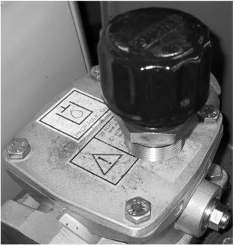
5.Check the hydraulic oil level indicator (1). Oil level should be visible in the sight gauge (2). See Fig. 29. If hydraulic oil is required, proceed to step 5.
6.Remove the rear cover and slowly open the breather filter (3) with a cloth to relieve pressure. Slowly open hydraulic oil filler cap (4) and then remove cap. See Fig. 29.
Note: A short hex shaft is included in the tool kit. This tool is designed to be used with a standard ratchet wrench to open the filler cap.
7.With the filter insert (5) in place, add hydraulic oil until oil level is between the marks on sight gauge.
Important!
Do not overfill the hydraulic oil reservoir, or damage to the system/leaks can result.
8.Re-install hydraulic oil filter insert and filler cap and tighten securely.
9.Start engine and let it idle for a few minutes.
10.Check hydraulic functions. Recheck hydraulic oil level.
Changing hydraulic oil
1.Operate the machine until it reaches operating temperature.
2.Position the machine on a level surface.
3.Fully extend the bucket and boom, and retract arm, as shown in See Fig. 28. Lower bucket and dozer blade to the ground. Turn off the machine.
4.Slowly open the filler cap to relieve pressure (1) Fig. 29.
5.Remove the hydraulic reservoir cover (2) Fig. 29 and remove filter insert (5) Fig. 29.
Important!
The filler cap and filter assembly will be removed over the rear cover. Protect rear cover from spilled or dripping hydraulic fluid.
6.Open the reservoir drain plug and drain oil into a suitable container. Re-install drain plug and tighten securely.
Important!
Always dispose of hydraulic fluids according to environmental law or take to a recycling center for proper disposal. DO NOT pour onto the ground or down a drain.
7.Reinstall filter insert (5).
8.Fill reservoir with hydraulic oil until oil level is between marks on sight the gauge.
9.Re-install the hydraulic reservoir cover (2) and tighten securely.
10.Start engine and let it idle for a few minutes. Cycle all front attachment hydraulic functions and recheck hydraulic oil level.
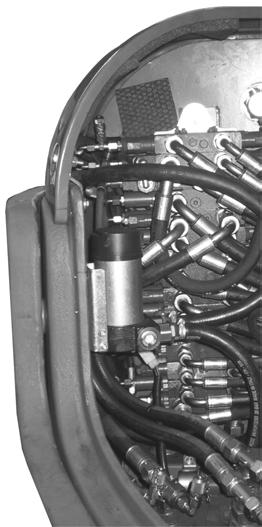
Hydraulic cooling system
The hydraulic system uses a hydraulic cooler to keep the hydraulic fluid at the proper temperature. The cooler is located inside the engine compartment near the engine radiator. Inspect the cooler for leaks or damage.
Hydraulic oil filter indicator
See Instrument panel, switches and indicators on page 1-8
The hydraulic oil filter indicator light illuminates when the hydraulic oil filter needs to be replaced. See Instrument panel, switches and indicators on page 1-8
Note: In cold weather, the hydraulic oil filter indicator light may illuminate immediately when the engine is started. This is increased by increased oil viscosity. The light should go out when engine reaches operating temperature and speed.
Checking hydraulic pressure lines
Specific safety instructions
WARNING!
Hydraulic reservoir is under pressure. Never use your hands to search for hydraulic fluid leaks; use a piece of paper or cardboard to find leaks. Escaping fluid under pressure can be invisible and can penetrate the skin, causing serious injury. If any fluid is injected into your skin, see a doctor immediately. Injected fluid MUST be surgically removed by a doctor familiar with this procedure, or gangrene may result.
Release hydraulic system pressure before re-tightening leaking screwed fittings and hose connections.
Never weld or solder faulty or leaking pressure lines and connections. Replace damaged parts with new ones.
• Leaks and damaged pressure lines must be immediately repaired or replaced. This not only increases the operating safety of your machine but also helps to protect the environment.
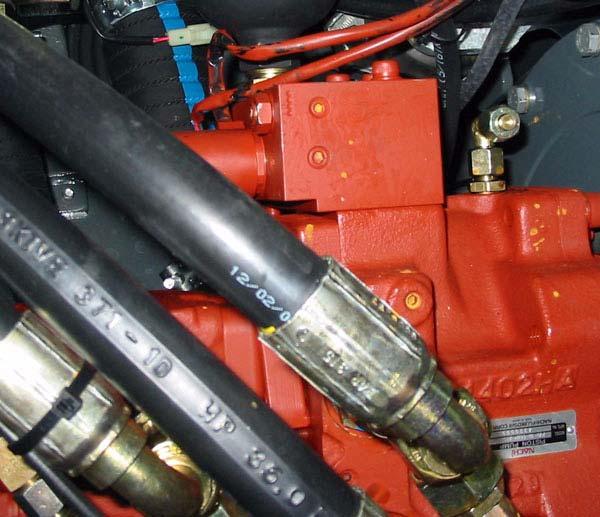
• Replace hydraulic hoses every six years from the date of manufacture, even if they do not appear to be damaged
In this respect, we recommend that you follow all the relevant safety regulations for hydraulic lines, as well as the safety regulations regarding accident prevention and occupational health and safety in your country. Also follow DIN 20 066, part 5.
The date of manufacture (month or quarter and year) is indicated on the flexible line.
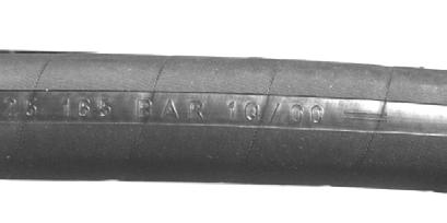
Example:
The indication “1 Q/05” means manufactured in the 1st quarter of 2005.
3.18Cab heater filter
Replacing the inside heater filter
Tilt the cab to replace the filter. See Tilting the cab on page 1-13. The heater is located at the rear half of the cab.
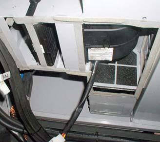
Replacing the filter:
1.Open the heater cover.
2.Replace the heater filter (Fig. 29).
3.Replace and secure the heater cover.