15 minute read
1Operation


1.1Important information about this ser vice manual
WARNING!
•Read and understand the excavator operator’s manual. Follow warnings and instructions for operation and maintenance in that manual. Failure to follow instructions can result serious injury.
•Read and understand all safety decals before operating the machine. DO NOT operate the machine unless all factory-installed guards and shields are in place.
•Be sure you are familiar with all safety devices and controls before operating the machine.
•Know how to stop the machine before starting.
This service manual contains important information about safely servicing the machine, correctly and economically. It serves as a reference for experienced users, helps to avoid hazardous situations, and reduces repair costs and downtimes. Additionally, the reliability and the service life of the machine will be increased by following the instructions in this manual.
Proper and careful work is the best protection against accidents!
Operational safety and readiness of the machine depends not only upon operator skill, but also upon proper maintenance and service.
Always use original Mustang service parts when performing maintenance and repair work. This ensures operational safety and readiness of the machine, and maintains its value.
1.2Abbreviations/symbols
• This symbol stands for a list.
• Subdivision within lists or an activity. Follow the steps in the sequence in which they appear.
☞ This symbol requires you to perform the activity described.
➥ Description of the effects or results of an activity.
n. s. = not shown.
“Option” = optional equipment. Stated whenever controls or other components of the machine are installed as an option.
1.3Identification of warnings a nd hazards
The following signal words are used throughout this manual and on decals on the machine to warn of potentially hazardous conditions.
DANGER!/WARNING!/CAUTION!
Failure to follow the instructions identified by this symbol may result in personal injury or death for the operator or other persons.
☞ Measures for avoiding the hazard may be included.
IMPORTANT!
Contains instructions to help use the machine more efficiently.
NOTE:
Contains additional instructions and/or helpful information.
Environment!
Failure to follow the instructions identified by this symbol may result in damage to the environment. The environment is in danger if environmentally hazardous material (e.g., waste oil) is not subject to proper use or disposal.
1.4Designated use and exemption from liability
• The machine is intended for:
• Moving earth, gravel, coarse gravel or ballast and rubble.
• Working with Mustang-approved implements.
• The Mustang Company is not liable for damage resulting from use other than mentioned above.
• Designated use also includes following instructions in the operator’s manual and observing maintenance and service recommendations. Read and understand the operator’s manual before starting, servicing/repairing the machine.
• The safety of the machine can be compromised by performing modifications to the machine not authorized by the Mustang Company and/or by using service parts, equipment or implements not approved by the Mustang Company. The Mustang Company is not liable for any damages resulting if this instruction is not followed.
• Follow the safety instructions in this manual, the operator’s manual, the engine manual, and any applicable instructions/manuals provided with any attachments used with the machine. The Mustang Company is not liable for personal injury and/or property damage resulting from failure to follow the safety instructions.
• The Mustang Company is not liable for personal injury and/or property damage resulting from failure to exercise care while servicing/repairing the machine.
• Do not use the machine for transportation on public roads.
Operation
1.5Type labels a nd component numbers
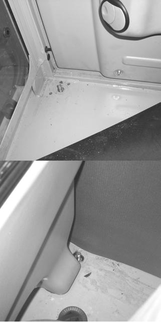
Serial number location
The machine serial number plate (1), Fig. 1 is located on the front frame, below the operator’s cab. The cab/canopy serial number (2) is located on the right rear of the frame next to the rear window.

Engine number
The type label (Fig. 2) is located on the engine cylinder-head cover.
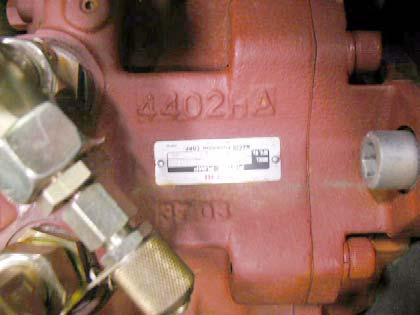
Hydraulic pump identification number
Operation
The hydraulic pump identification number is located on the hydraulic pump housing (Fig. 3).
Main valve block identification number


The main valve block identification number is located on the lower side of the main valve block (Fig. 4).
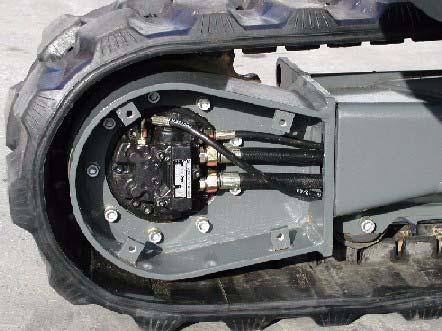
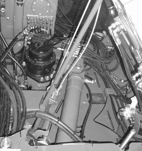
Travel drive identification number
Refer to Fig. 5 for the travel drive identification number location.
Swivel unit identification number
Refer to Fig. 6 for the swivel unit identification number location.
1.6Machine: overview
Dipper Arm Cylinder Boom
Dipper Arm
Bucket Cylinder
Bucket
Boom Light
Boom Cylinder
Dozer Blade
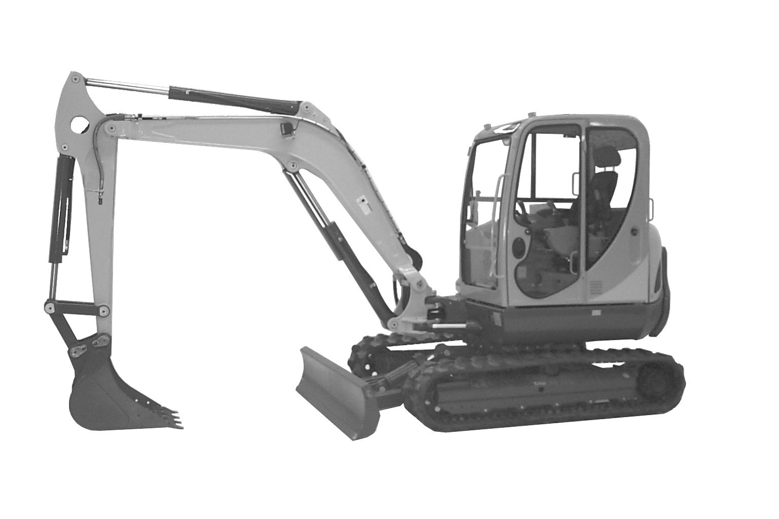
Operation
Cab
Engine Cover
Operator’s Seat
Hydraulic/Fuel Tank Cover
Counterweight
Swing Frame/ Superstructure
Travel Drive Motor
Track Frame
Operation Controls Swing Cylinder
Operation
Ref. Description
1Auxiliary hydraulics pedal cover
2Auxiliary hydraulics pedal
3Control lever (left)
4Control lever (right)
5Control lever base (left)
6Control lever base (right)
7Armrest (left)
8Armrest (right)
9Lever – horizontal seat adjustment
10Lever – horizontal seat adjustment with control lever base
11Air vent (rear window, on the left)
12Air vent (rear window, on the right)
13Radio (option)
14Seat (back rest adjustment)
15Seat belt (lock)
16Cup holder
17Bracket (storage box for documents)
18Switch panel
19Throttle
20Fuse box
21Pre-heating/ignition switch
22Accessory power outlet
23Coolant temperature indicator
24Instrument cluster
25Drive pedal (left)
26Drive pedal (right)
27Drive lever (left)
28Drive lever (right)
29Dozer blade pedal/lever
1.8Instrument panel, switches and indicators
Ref. Description
30 Hydraulic oil filter indicator (red) – Hydraulic oil filter indicator light comes on when hydraulic oil filter is too dirty.
31 Air filter indicator (red) – Air filter indicator light comes on when air filter is too dirty.
32 Battery charge indicator (red) – Battery charge indicator light comes on when the ignition is turned on and turns off as soon as the engine runs. The alternator or the charging circuit is faulty if the indicator light comes on with the engine running. The battery is no longer charged.
33 Engine oil pressure indicator (red) – Engine oil pressure light comes on when the ignition is turned on and goes out as soon as the engine runs. During normal operation, this indicator should remain off. The indicator will light if the engine oil pressure drops too low. If this occurs shut on the engine IMMEDIATELY and determine the cause of the pressure drop.
34 Coolant temperature indicator (red) – Coolant temperature indicator light comes on when coolant temperature is too high.
35 Glow plug indicator (yellow) – Glow plug indicator light comes on when the ignition key is to the glow plug activation position. Indicator will go out when the glow plugs have heated sufficiently to start the engine.
36 Hour meter – Indicates the total operating hours of the machine. Use the hour meter to track maintenance in the maintenance log.
37 Fuel level gauge – The fuel level gauge shows the amount of fuel in the tank. 38 Indicator light –
40 Hydraulic oil temperature indicator light – Hydraulic oil temperature indicator light comes on when hydraulic oil is too hot.
41 Coolant temperature gauge – Displays coolant temperature.
42 High-speed switch (transport speed) – Pressing the switch will enable high travel speed.
43 Windshield wiper switch (cab models only) – Pressing the two position switch to the first position turns the windshield wiper on. Pressing and holding the switch indicator in the second position activates the washer fluid pump.
44 Work light switch – Press switch to the ON position to turn on the boom work light.
45 Roof lights (option) – Press switch to the ON position to turn on the roof light lights.
46 Rotating beacon (option) – Press switch to the ON position to turn on the boom work light.
47 Ventilation Fan (two-speed) – Press the two position switch to turn on the ventilation fan. Pressing switch to the first position is the low fan speed position and the second position is the high fan speed position. If the Summer/Winter operation valve is OPEN or HEATING position, this switch will function as the Cab Heater ON/OFF switch. The Summer/Winter operation valve is located under the hood on top of the engine behind the radiator. 48 Air conditioning (option) – Press the switch to turn on the air conditioning.

1.10Chassis: overview
Operation
1.11SAE/ISO operating co ntrols selector valve
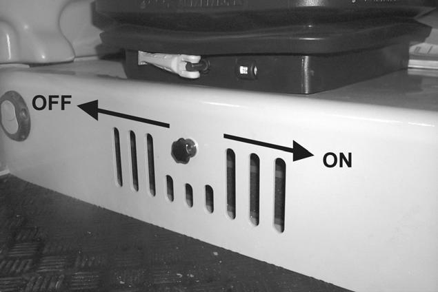
Located on the lower left side of the cha ssis, under the cab, is the SAE/ISO selector Valve. See (1), Fig. 8. The SAE/ISO valve can be accessed through a cutout on the left side of the chassis at location (2). This machine has been set at the factory for SAE standard operation shown at position (3). If ISO operation is desired, loosen wing nut (5) and rotate valve to position (4) and tighten wing nut (5). If the machine does not function according to the decals and instructions in this manual, move the selector valve to the other position.


1.12Tilting the cab
Refer to 1-10 (Fig. 9) to safely complete the following procedure.
Tilting the cab up:
1.Follow “Mandatory Safety Shutdown Procedure” in the "Safety" Chapter of the Operator’s Manual.
2.Raise the floor mat (1) on the right, front of the cab and remove cab lockdown nut (2). Remove cab lock-down nut (3) at the right rear of the cab.
3.Securely close the cab door.
4.Locate the jack handle tubes (4) from the tool kit in the engine compartment and insert into the jack (5) and jack to the limit. The cab will be raised as far as the jack (5) will travel.
5.Pull handle (7) until the cab is completely tilted and supported by safety cables (8).
6.Remove the tilt rod (9) from the storage bracket (10) and slide the tilt rod (9) into the guide bracket (11) and secure with the split pin.
Tilting the cab down:
1.Remove the tilt rod (9) from the guide bracket (11) by removing the split pin and slide the tilt rod (10) out of the guide bracket (9) and secure with the split pin back in the storage bracket (10).
2.Use handle (7) to slowly lower the cab back onto the jack (5).

3.Remove jack handle tubes (4) from the jack (5) and insert the opposite end of the jack handle tubes (4) onto the release pin (6). Slowly turn release pin (6) counter-clockwise until the cab is lowered.
4.Turn the release pin (6) clockwise.
Operation
5.Reinstall the cab lock-down nuts (2) and (3).
6.Place the jack handle tubes (4) back in the tool kit.
1.13SAE operating controls (standard)
WARNING!
•Always tighten cab lock-down nuts before driving or using the machine.
•Always close the cab door before tilting the cab.
•Stay clear from underneath the cab as it is tilted.
•Always secure the tilt rod in the support position the when cab is tilted.
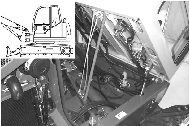
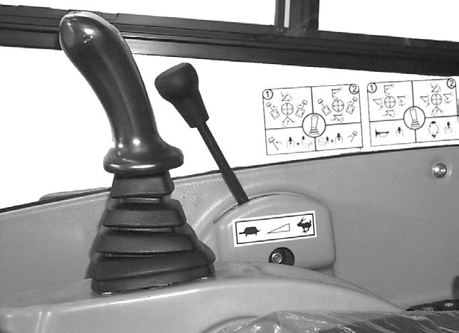
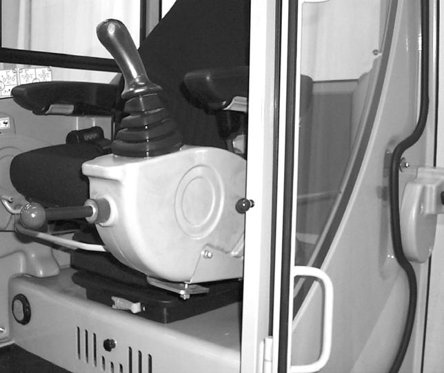
SAE boom and bucket functions are controlled by the right and left-hand joystick control levers located on the seat consoles.
Left-hand joystick
1 – Arm extend
2 – Arm retract
3 – Swing left
4 – Swing right
SAE right-hand joystick
5 – Boom lower
6 – Boom raise
7 – Curl bucket in
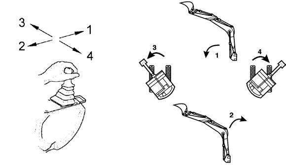
8 – Curl bucket out
Note: The joystick controls are pilot-operate d. The farther the controls are moved from center, the faster the machine will function.
1.14ISO operating co ntrols (selectable)
ISO boom and bucket functions are controlled by the right and left-hand joystick control levers located on the seat consoles.
ISO left-hand joystick
1 – Boom lower
2 – Boom raise
3 – Swing left
4 – Swing right
ISO right-hand joystick
5 – Arm extend
6 – Arm retract
7 – Curl bucket in
8 – Curl bucket out
Note: The joystick controls are pilot-operated . The farther the controls are moved from center, the faster the machine will function.
1.15Boom slew/auxiliary hydraulics pedal
The boom can be slewed, or swung, without moving the swing frame by pressing and holding the auxiliary hydraulic/changeover valve button (1) on top of the left hand joystick, and then pressing the auxiliary hydraulics pedal (2) left or right. See Fig. 14.


Pressing and holding the auxiliary hydraulic/changeover valve button (1) and pressing the auxiliary hydraulics pedal (2) to the left with your toe slews the boom to the left. Pressing and holding the auxiliary hydraulic/changeover valve button (1) and pressing the auxiliary hydraulics pedal (2) to the right with your toe slews the boom to the right.
The auxiliary hydraulics pedal (2) allows use/control of front end attachments. Action will vary depending on the attachment and how it is connected.
Operation
1.16Dozer blade
The dozer blade is controlled by the dozer control pedal/lever (1) located next to the travel controls. See Fig. 15.

•Push control pedal/lever forward to lower the blade.
•Pull control pedal/lever rearward to raise the blade.
1.17Throttle lever
The engine RPM is controlled by the throttle lever (1) located next to the right hand control console. See Fig. 16.
•Push throttle lever (1) forward to lower the engine RPM.
•Pull throttle lever (1) rearward to increase the engine RPM.
Operation
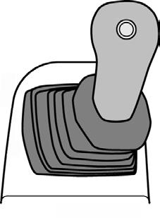
1.18Operator’s seat adjustments
Note: The operator’s seat left-hand console must be raised in order to exit the cab. In the lowered or work position, all operational functions are activated, and operator exit is blocked by the warning arm/lever. In the raised position, the all hydraulic functions of the machine are locked out.

1.Seat Suspension Adjustment
Rotate the knob (1), Fig. 17 to adjust the seat suspension for the operator’s weight. An indicator on the front of the seat base shows the weight adjustment in kilograms. (1 kg = 2.2 lbs.) Adjust the seat suspension correctly to ensure a comfortable ride.
2.Horizontal Seat Adjustment
The seat adjustment lever (2) allows the operator to move only the seat forward and rearward.
Operation
3.Horizontal Seat & Control Adjustment
The seat adjustment lever (3) allows the operator to move both the seat and the controls forward and rearward.
4.Armrest Height Adjustment
The armrest height adjustment (4) allows the operator to raise or lower the armrests by turning the adjustment wheel. The rear of the left-hand armrest has a turnbuckle that may need to be adjusted to allow the left-hand armrest to rotate out of the way when the left-hand console is raised. Use the turnbuckle to adjust the armrest so it does not contact the left-hand control lever when raising the left-hand console to the lock-out position.
5.Backrest Adjustment
The backrest adjustment lever (5) allows the operator to move the backrest forward and rearward.
6.Headrest Adjustment
The headrest adjustment (6) allows the operator to move the headrest up and down.
7.Seat Height Adjustment
The seat height adjustment allows the operator to move the seat height up and down. To raise the seat height, grasp the seat and lift up until you hear an audible click. To lower the seat, raise the seat to the highest position and then lower the seat to its lowest position.
1.19Ventilation
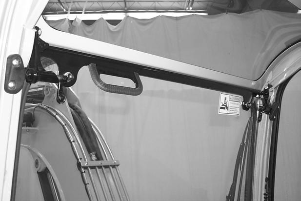
When opening the windshield, be sure to lock both latches. When closing the windshield, keep hands on handle and away from path of window.
1.The windshield can be opened for ventilation. Turn the latches (1), Fig. 18 located at the upper corners of the windshield. Grasp the handle (2) and pull the windshield up until the latches lock in the open position. For additional ventilation, the lower portion of the windshield can be removed and securely stored in the glass holder (3) located on the rear window.
2.To close the windshield, reinstall the lower windshield, and turn the latches, and then lower the windshield and lock the latches in the closed position.
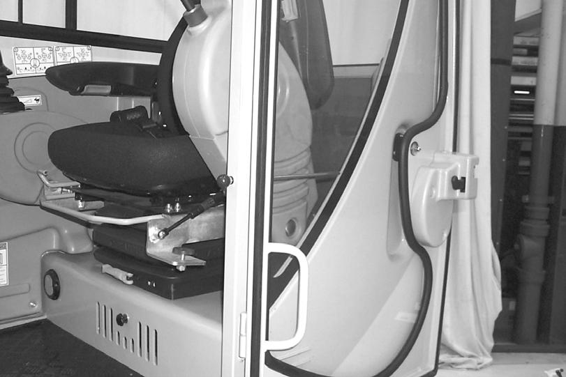
1.20Cab door latch release
When fully opened, the left-hand cab door will lock in position to the side of the cab. To release the latch, use the black knob (1), Fig. 19 located on the inside of the door.

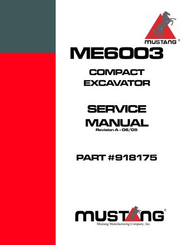
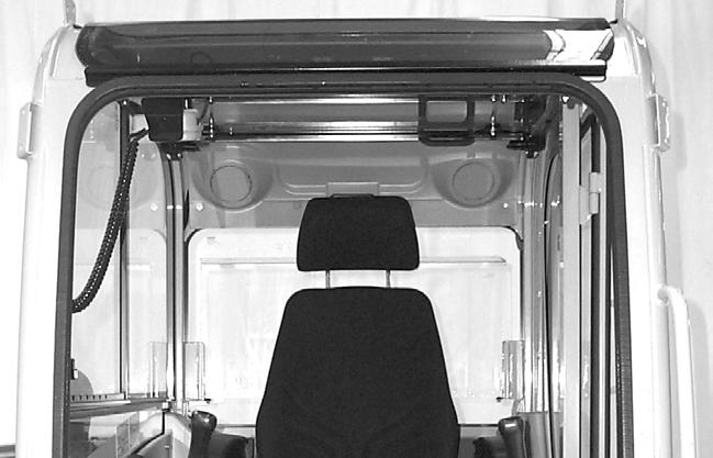
1.21Interior light
The interior light is located on the back of the cab above the rear window. Press the switch to the right or left to turn the light ON. Move the switch to the center position to turn the light OFF.

1.22Tool kit and cab jack handle
The machine tool kit and the cab jack handle are located in the storage area under the hood in the engine compartment.
1.23Cab
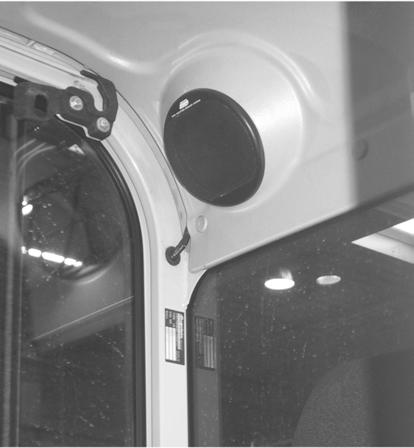
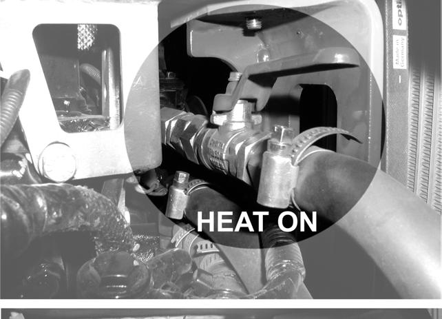
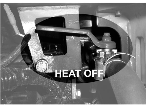
During the colder months, the operator’s cab heater can be turned on by opening the heater valve located under the hood on top of the engine behind the radiator (Fig. 21). Rotate the lever to either the “heat on” or “heat off” position as required.
1.24Recirculated air mode
Operation
When heating or cooling the cab, the recirculated air mode can be utilized to heat or cool only the air in the cab with no fresh air supply from the outside. Sliding the plate to the left will turn ON the recirculated air mode by closing the vent. Sliding the plate to the right will turn OFF the recirculated air mode by opening the vent.
Mode
1.25Hydraulics/swiveling and boom rotation pedal adjustment
The pedal operating the auxiliary hydraulics/swiveling the boom can be rotated by 90°.
1.Loosen 4 screws.
2.Rotate the pedal by 90°.
3.Tighten the 4 screws.
CAUTION!
Make sure the hydraulic hoses are not squeezed as you tilt the cab.
1.26Battery master switch
IMPORTANT!
The battery power circuit is supplied with a keyswitch. Use the keyswitch to disconnect power before working on the electric system and/or as an anti-theft precaution.
Interrupting power supply
Turn key (A) of the battery master switch to position (B) and remove it.
Switching on power supply
1.Insert key (A) in the battery master switch.
2.Turn the key down to the notched position (C).
Specifications
2Specifications
2.1Chassis
2.2Engine
Sturdy steel sheet chassis, rubber-mounted engine
Engine Model Yanmar 4TNV98-VNS EPA Tier II
Engine Type
Water-cooled 4 stroke diesel engine
No. of cylinders 4
Fuel injection system
Aspiration
Cooling system
Lubrication system
Direct injection
Naturally aspirated
Water-cooled/aspirating fan
Force-feed lubrication with trochoidal pump
Displacement 202 cu. in. (3.32 L)
Nominal bore and stroke 3.9 x 4.3 in. (98 x 110 mm)
Output 57 hp (42.5 kW) @ 2100 rpm
Max. torque 184 lb.-ft. (249 Nm) @ 1400 rpm
Max. engine speed without load 2275 +/- 50 rpm
Idling speed 1050 +/- 50 rpm
Valve tip clearance (intake = outlet) 0.006 – 0.010 in. (0.15 – 0.25 mm) (cold)
Injection pressure 3191 – 3336 psi (220 – 230 bar)
Compression 507 +/- 14.5 psi (35 +/- 1 bar) @ 250 rpm
Engine oil pressure 48 – 58 psi (3 – 4 bar)
Pressure switch for engine oil pump 7.25 +/- 0.1.5 psi (0.5 +/- 0.1 bar)
Opening temperature of thermostat 157 – 163 °F (69.5 – 72.5 °C)
Thermal switch 225 – 235 °F (107 – 113 °C)
Firing order 1 - 3 - 4 - 2 - 1
Direction of rotation
Starting aid
Max. inclined position (engine no longer supplied with oil):
Counter-clockwise (as seen from the flywheel)
Intake manifold (pre-heating time 10 – 15 sec)
25°/46% in all directions
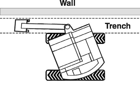
NOTE: this is exceeded by the machine’s theoretical climbing ability (30°/58%)
Exhaust values according to 97/68/EC Tier II
EPA Tier II
Specifications
Capacities
1. max: Oil quantity up to oil dipstick max mark effect\: Oil quantity between min and max oil dipstick marks Overview of capacities: – see Fluids and lubricants on page 3-23
Engine Tightening
2.3Hydraulic system
Auxiliary hydraulics oil flow*
* Output specifications for auxiliary hydraulics with unpressurized return line
Screwable hose burst valve
Specifications
2.4Undercarriage/swivel unit
2.5 Dozer blade
2.6 Electrical system
Fuse box in instrument panel
Specifications
Fuse No. Rated Current Protected Circuit
F310 AmpIndicators, cut-off solenoid, relays
F410 AmpBoom light
F515 AmpRoof lights
F610 AmpValves, horn
F715 AmpHeating, air conditioning
F810 AmpWindshield wiper, interior light
F910 AmpRotating beacon, radio
F1015 AmpSocket, cigarette lighter
F410 AmpBoom light
Main fuse box with relays (located under cab)

Fuse No. Rated Current Protected Circuit
F140 AmpStar, pre-heat, cut-off solenoid
F250 AmpMain fuse, ignition lock
Relay No. Protected Circuit
K9Cut-off solenoid
K5Pre-heating
Specifications
Relays - (located under cab)

2.7 Sound levels
Note: Measurement of sound power level according to EC Directive 2000/14/EC. Sound level in the cab measured according to EC Directives 84/532/EEC, 89/514/EEC and 95/27/EEC. Measurements performed on asphalted surface.
2.8Fluid capacities
2.9Coolant compound table
2.10Specific tightening torques
Specifications
2.11General tightening torques
Note: Use these torque values when tightening hardware (exclu ding: locknuts and self-tapping, thread forming and sheet metal screws) unless specified otherwise.
Hydraulic fittings with various seals (light application). All torque values are in lb.-ft. (Nm) unless marked otherwise.
Thread Straight pipe fitting with thread and screwed plug (GE) Non-return valve with elastic seal Identification aid outside Ø Sealing washerElastic sealO-ring
Hydraulic fittings with various seals (heavy application). All torque values are in lb.-ft. (Nm) unless marked otherwise.
Thread Straight pipe fitting with thread and screwed plug (GE) Non-return valve with elastic seal Identification aid outside Ø Sealing washerElastic sealO-ring
With coarse-pitch thread. All torque values are in lb.-ft. (Nm) unless marked otherwise.
With fine-pitch thread. All torque values are in lb.-ft. (Nm) unless marked otherwise.
Specifications
2.12Dimensions
General Specifications
Weight12,566 lbs. (5700 kg)
Height8’5” (2570 mm)
Width6’6” (1990 mm)
Transport length19’0” (5800 mm)
Dipper arm length (Standard Arm)5’6” (1685 mm)
Dipper arm length (Optional Long Arm)6’6” (1985 mm)
Max. digging depth w/ Standard Arm12’7” (3845 mm)
Max. digging depth w/ Optional Long Arm13’7” (4140 mm)
Max. vertical digging depth w/ Standard Arm9’4” (2855 mm)
Max. vertical digging depth w/ Optional Long Arm10’3” (3135 mm)
Max. digging height w/ Standard Arm18’6” (5660 mm)
Max. digging height w/ Optional Long Arm19’2” (5850 mm)
Max. dump height w/ Standard Arm13’1” (3995 mm)
Max. dump height w/ Optional Long Arm13’8” (4185 mm)
Max. digging radius w/ Standard Arm20’ 4” (6210 mm)
Max. digging radius w/ Optional Long Arm21’3” (6490 mm)
Max. reach at ground level w/ Standard Arm19’11” (6090 mm)
Max. reach at ground level w/ Optional Long Arm20’11” (6380 mm)
Max. breakout force at bucket tooth8,925 lbf (39.7 kN)
Max. tearout force (Standard Arm)6,317 lbf (28.1 kN)
Max. tearout force (Optional Long Arm)5,642 lbf (25.1 kN)
Min. tail end slewing radius4’9” (1465 mm)
Max. tail end lateral projection over tracks1’6” (470 mm)
Max. boom distance to bucket center (right-hand side)2’5” (745 mm)
Max. boom distance to bucket center (left-hand side)1’9” (535 mm)
Max. boom slew angle (left-hand side)75°
Max. boom slew angle (right-hand side)51°