33 minute read
Maintenance

from Mustang 1750RT 1750RT NXT2 2100RT 2100RT NXT2 2500RT Compact Track Loader Operator’s Manual 50940163

Proper care and service improves machine operational readiness and service life.
Perform maintenance as indicated in the “Maintenance Schedule” on page118, or earlier if required by conditions.
Warning
Read and understand the “Safety” Chapter in this manual, starting on page17, before servicing the machine. Follow all applicable warnings and instructions. Check for correct function after performing maintenance. Failure to follow instructions can result in injury or death.
BEFORE performing any maintenance, perform the MANDATORY SAFETY SHUTDOWN PROCEDURE. See “Mandatory Safety Shutdown Procedure” on page18.
Fluid leaks from hydraulic hoses or pressurized components can be difficult to see, but pressurized oil can have enough force to pierce the skin and cause serious injury. Always use a piece of wood or cardboard to check for suspected hydraulic leaks. Never use your hands. Obtain immediate medical attention if pressurized oil pierces the skin. Failure to obtain prompt medical assistance could result in gangrene or other serious damage to tissue.
Do not smoke or allow any open flames in the area while checking or servicing the hydraulic, battery and fuel systems because all contain highly flammable liquids or explosive gases, which can cause an explosion or fire if ignited.
Wear a face shield when disassembling spring loaded components or working with battery acid. Always wear eye protection to protect eyes from electric arcs from shorts, fluids under pressure, and flying debris or loose material. Wear a helmet or goggles with special lenses when welding or cutting with a torch.
Warning
When working beneath a raised machine, always use blocks, jack-stands or other rigid and stable supports. Wear appropriate protective clothing, gloves and shoes. Keep feet, clothing, hands and hair away from moving parts.
Always apply the lift arm support when maintenance work requires the lift arm in the raised position See “Lift Arm Support” on page99.
NEVER weld on the machine without the consulting the manufacturer. Special metals may be used, which require special welding techniques or parts be designed so that they should not be welded. NEVER cut or weld on fuel lines or tanks.
If repair welding is ever required, remove the positive (+) battery terminal connection before starting to weld. Be sure to attach the ground (-) cable from the welder as close as possible to the area to be repaired.
Allow only trained and authorized personnel, with full knowledge of safe procedures, to perform machine maintenance and service.
If any guards, shields and covers were removed during maintenance, BE SURE to replace them in their original positions BEFORE starting the machine.
Caution
Do not use the machine when maintenance is due. Postponed maintenance can result in a serious reduction of the service life of the machine, costly equipment failures, and contribute to unsafe operating conditions.
Do not perform maintenance or service not included in this manual. Maintenance and service not included in this manual should only be performed by a authorized repair shop.
Maintenance Schedule
IMPORTANT: Maintenance intervals apply to average operating conditions and loads. More frequent maintenance may be required depending upon the level and type of use.
Log all maintenance as it is performed in the “Maintenance Log” on page157.
NOTE: Refer to the hour meter and the required maintenance display screen to determine maintenance interval timing. See “Maintenance Interval” on page120.
Checks,
Table 4: Checks Cleaning
1.Model 2500RT: Multi-function screen displays the engine error code “97-12” if water is present in water separator. See “Engine Error Code Screen” on page49 and “(Model 2500RT) Fuel prefilter sensor error” on page168
Leakage Check
Table 5: Leakage Check
Lubrication and Filter Changes
Functional Check
Maintenance Interval CAUTION
Do not postpone maintenance. Postponed maintenance can result in a serious reduction to the service life of the machine, more serious and costly equipment failures and can contribute to unsafe conditions.
NOTE: The display screen on the multi-function display includes an “Accumulated Service Hours Screen”. See page48. This screen displays accumulated operation time, which accumulates whenever the engine is running.
NOTE: Additional “Maintenance Required Screens” display at 50, 250, 500, 750, etc. (ongoing) service hour intervals. See page48. These screens function as reminders that important maintenance is due.
IMPORTANT: “Maintenance required” screens display in rotation along with other status screens in the multi-function display. To dismiss “maintenance required” screens, press and hold the multi-function display interface button for 5 seconds.
IMPORTANT: If a “maintenance required” screen is not dismissed, it is still possible to page through the other screens for one rotation only. After this, the “maintenance required” screen will remain displayed until it is dismissed.
Engine Maintenance
Engine Access
1.Use the ignition key to unlock the latch (A, Fig. 120) on the top engine compartment cover. Pull up on the latch and lift the cover.
2.Pull up on handle (B) inside the top left lip of the rear door. Swing the door open to access engine components.
NOTE: Opening the rear door all the way engages stop (S, Fig. 121), which holds the door open.
Closing Engine Covers
1.Lift up on the rear door stop (S), and firmly close the rear door.

NOTE: It is important for the rear door to close and latch completely, so the top engine cover latch aligns properly with the pin on the rear door. Incomplete latching of the rear door/top cover may cause latches to stick.
2.With the rear door completely closed and latched, firmly close the top engine cover until it is completely closed and latched.

Engine Oil
Checking Engine Oil Level
Check the engine oil level daily before starting the machine, or after every ten hours of use.
1.Park the machine on a level surface.
2.Perform the “Mandatory Safety Shutdown Procedure” on page18.
3.Wait until the engine has cooled. See “Maintenance and Service Safety Practices” on page23.

4.Open the engine cover “Engine Access” on page121.
5.Twist engine oil dipstick (C, Fig. 122) counterclockwise to unlatch it. Remove the dipstick from the engine.


6.Wipe the dipstick with a clean cloth and replace it in the engine. Push it in until it is fully inserted.

7.Remove the dipstick again. The oil level should be within the “Add” and “Full” marking.
8.If the oil level is below the “Add” marking: a. Clean the area around the oil fill cap (G) with a clean cloth. b.Remove fill cap (G). c.Add oil through the fill cap opening until the level reaches the “Full” mark. d.Replace and tighten fill cap (G).
IMPORTANT: Do not over-fill the engine with oil. Damage could result.
Changing Engine Oil and Filter
Change the engine oil and filter after the first 50 hours of use, and every 250 hours thereafter.
1.Park the machine on a level surface.
2.Perform the “Mandatory Safety Shutdown Procedure” on page18.
3.Wait until the engine has cooled, but is not completely cold. Oil will drain faster and more completely if it is warm.
4.Open the engine cover “Engine Access” on page121.

5.Remove hardware (M, Fig. 123) securing engine drain plug access panel (N). Remove panel to access engine oil drain plug (O).
NOTE: On Model 2500RT, and Models 1750RT and 2100RT with oil filters located on the side of the engine, oil filter (D, Fig. 125) is accessed through the drain plug access hole (Q, Fig. 123).
7.Remove drain plug (O) from the engine oil pan and allow the oil to drain into the waste oil collection container.
NOTE: On Model 1750RT (Serial Numbers 131000 and before), and Model 2100RT (Serial Numbers 241000 and Before), oil drain plug (O) is located on the side of the oil pan.
8.Remove oil filter (D, Fig. 124), using a filter wrench if necessary. Carefully clean the filter head mounting surface with a clean cloth.

NOTE: On Model 2500RT, and Models 1750RT and 2100RT with oil filters located on the side of the engine, oil filter (D, Fig. 125) is accessed through the drain plug access hole (Q, Fig. 123).
6.Position a waste oil collection container under the engine oil drain plug to catch draining oil.

IMPORTANT: Dispose waste engine oil according to environmental laws, or take to a recycling center for proper disposal. DO NOT pour waste engine oil onto the ground or down a drain.

9.Apply a coating of clean oil on the new oil filter gasket. Install the filter and tighten 3/4 rotation past the point where the gasket contacts the filter head.
10.Re-install and tighten the drain plug.
11.Clean the area around oil fill cap (G, Fig. 125). Remove oil fill cap (G) and add the recommended type and amount of oil. See “Fluids/Lubricants Types and Capacities” on page33. Replace and tighten oil fill cap (G) after the oil is added.
NOTE: Oil capacity listed is approximate. Always verify proper oil level with the engine oil dipstick.
IMPORTANT: Do not over-fill the engine with oil. Damage could result.
12.Start the engine and let it run for several minutes at low idle. Watch for leaks at the oil filter and drain plug. Stop the engine and wait for it to cool.

13.Check the oil level. Add oil if necessary until the oil level is at the “Full” mark on the dipstick (Fig. 122).
14.Replace engine drain plug access panel (N, Fig. 126). Secure with hardware (M).
Engine Air Filters
IMPORTANT: Do not operate the engine without the air cleaner components installed or damage to the engine could occur.
Check, and if necessary replace, the engine air filters after every 250 hours of use, or every 6 months, or whenever the engine air filter restriction indicator is lit (F, Fig. 127).
NOTE: The engine air filter restriction indicator (F, Fig. 127) on the multi-function display is lit whenever the air cleaner becomes restricted. When this indicator is lit, the air filters require inspection and may need replacement.
Changing Air Filter Elements
1.Perform the “Mandatory Safety Shutdown Procedure” on page18.
2.Open the engine cover “Engine Access” on page121.
The air cleaner consists of an outer (primary) filter element (G, Fig. 129), an inner (secondary) filter element (H) and an optional pre-cleaner.

Replace the inner filter element every third time the outer element is replaced, unless the outer element is damaged or the inner element is visibly dirty.
Be sure the air cleaner intake hose, clamps and mounting bracket hardware are properly tightened.
3.Unlatch clamp (J, Figs. 128 and 129) on the air cleaner housing and remove the air filter cover (L).

4.Clean debris from inside the air cleaner housing (M) and air filter cover.

Model 2500RT
Model 1750RT (S/N 131000 and Before)
Model 2100RT (S/N 241000 and Before)
5.Carefully remove the outer filter element (G). Do not remove inner filter element (H) unless it will be replaced. If inner filter element (H) will not be replaced, skip to step 10.
NOTE: On Model 1750RT (Serial Numbers 131001 and Up) and Model 2100RT (Serial Numbers 241001 and Up), pull tabs (Z) to remove out filter element (G) and pull tabs (Y) to remove inner filter element (H).
6.Clean dirt from inside the air filter housing (M).
IMPORTANT: To prevent debris from entering the engine intake manifold, do not remove inner filter element (H) while cleaning the inside of the housing.

7.Remove the inner filter element (H).
8.Check the inside of the housing for damage.
9.Install a new inner filter element (H).
10.Install a new outer filter element (G).
11.Replace air filter cover (L). Latch clamps (J). Make sure the cover is tightly secured and is seated properly in the housing.

Engine Cooling System
Checking Coolant Level
Check the coolant level daily before starting the machine, or after every ten hours of use.
1.Park the machine on a level surface.
2.Perform the “Mandatory Safety Shutdown
Procedure” on page18.
3.Wait until the engine has cooled. See “Maintenance and Service Safety Practices” on page23.

4.Open the engine cover “Engine Access” on page121.
5. Model 2500RT: a.Wait for the machine to cool completely.
Warning
Do not remove radiator cap when the coolant is hot. Serious burns may occur.
b.Remove the radiator cap. Coolant level is correct when it is level with the bottom of the radiator fill tube.
6. Models 1750RT/2100RT: Check the coolant level in the expansion reservoir (R, Fig. 130). Coolant level must be between the full (T) and low (S) marks on the expansion reservoir. Add coolant to the expansion reservoir as required.
IMPORTANT: The coolant system is specifically designed for coolant level top-off only through the expansion reservoir. Do not add coolant directly to the radiator.
NOTE: Use a low-silicate ethylene glycolbased coolant, mixed with quality water and supplemental coolant additives (SCAs) suitable for heavy-duty diesel engines. See “Fluids/Lubricants Types and Capacities” on page33 and the engine operation manual for additional information.
Cleaning Radiator Fins
The radiator fins can become blocked during use which will lead to reduced cooling function and engine overheating. Clean the radiator cooling fins after every 250 hours or 6 months of operation, whichever occurs first.
1.Perform the “Mandatory Safety Shutdown Procedure” on page18.
2.Wait until the engine has cooled. See “Maintenance and Service Safety Practices” on page23.
3.Open the engine cover “Engine Access” on page121.
4.Clean the radiator fins by blowing air/water through the fins from the rear of the radiator, toward the engine.
IMPORTANT: Use caution! High pressure can damage radiator fins.
Draining/Refilling Cooling System
1.Park the machine on a level surface.
2.Perform the “Mandatory Safety Shutdown Procedure” on page18.
3.Wait until the engine has cooled. See “Maintenance and Service Safety Practices” on page23.
4.Open the engine cover. See “Engine Access” on page121.
Warning
Do not remove radiator cap when the coolant is hot. Serious burns may occur.
5.Slowly loosen radiator cap (P, Fig. 131) and allow pressure to escape. Remove cap.

6.Position a suitable collection container, with a minimum capacity of 15 L (4 gals.) underneath the radiator.

IMPORTANT: Dispose waste coolant according to environmental laws. DO NOT pour coolant onto the ground or down a drain.
7.Access radiator drain plug (X, Fig. 132) through access hole (Y) in the frame underneath the radiator. Using an allen wrench, remove radiator drain plug (X) and allow the coolant to drain into the container.
8.Replace the radiator drain plug and tighten securely.
9.Fill the radiator with coolant.
NOTE: Use a low-silicate ethylene glycolbased coolant, mixed with quality water and supplemental coolant additives (SCAs) suitable for heavy-duty diesel engines. See “Fluids/Lubricants Types and Capacities” on page33 and the engine operation manual for additional information.
10.Reinstall radiator cap and tighten securely.
11.Start and run the engine until it reaches operating temperature.
12.Check the coolant level according to “Checking Coolant Level” on page126.
V-Belt Maintenance
Check V-belt condition monthly, or after every 100 hours of use. Replace or adjust if necessary.
NOTE: On model 2500RT machines, the V-belt is tensioned by a spring idler and requires no adjustment. Replace the belt if belt deflection exceeds 0.6” (15 mm). Refer to the engine operator’s manual for more details.

Checking and Adjusting V-belt Tension
1.Perform the “Mandatory Safety Shutdown Procedure” on page18.
2.Wait until the engine has cooled. See “Maintenance and Service Safety Practices” on page23.
3.Open the engine cover “Engine Access” on page121.
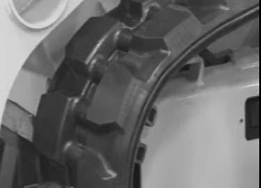
4.Inspect V-belt (A, Fig. 133) for damage. If damaged, have belts replaced by an authorized repair shop.
5.Press on V-belt (A) mid-way between pulleys to check deflection. The belt should not deflect more than 8 mm (5/16”).
6.If deflection is more than 8 mm (5/16”): Loosen adjustment bolt (C) and rotate alternator (B) outward until V-belt tension is correct. Tighten bolt (C) and re-check V-belt tension.

Air Conditioning V-Belt
Air conditioning V-belt (P, Fig. 134) tension is automatic and requires no adjustment.
Check air conditioning V-belt condition at regular intervals. Replace or adjust if necessary.

Fuel System Maintenance WARNING
Diesel fuel is flammable. Keep the machine away from open flames. Do not smoke when refueling or when working on the engine. Stop the engine before fueling.
Wear eye protection. The fuel system is under pressure and fuel could spray out when removing any fuel system component.
Wipe up spills immediately. NEVER use a shop rag to catch draining/leaking fuel. Vapors from the rag are flammable and explosive.
Failure to follow these instructions can cause fire and result in injury or death.
Caution
Use only proper types and grades of diesel fuel (See “Fluids/Lubricants Types and Capacities” on page33).
DPF Service
Models 1750RT (Serial Numbers 131001 and Up) and 2100RT (Serial Numbers 241001 and Up)
DPF filter soot filter replacement is required when the DPF Service screen (Fig 135) displays.
NOTICE: The fuel tank is filled at the factory with United States off-road grade diesel fuel, which is dyed red for identification. It may take several fillings of the fuel tank before the red dye is purged from the fuel system.
NOTE: Contact your dealer when the DPF Service screen displays.
Adding Fuel WARNING
Static electricity can produce dangerous sparks at the fuel-filling nozzle. Do not wear polyester, or polyester-blend clothing while fueling. Before fueling, touch the metal surface of the machine away from the fuel fill to dissipate any built-up static electricity. Do not re-enter the machine but stay near the fuel filling point during refueling to minimize the build-up of static electricity. Do not use cell phones while fueling. Make sure the static line is connected from the machine to the fuel truck before fueling begins.
Ultra-Low Sulfur Diesel (ULSD) poses a greater static ignition hazard than earlier diesel formulations. Avoid death or serious injury from fire or explosion; consult with your fuel or fuel system supplier to ensure the entire fuel delivery system is in compliance with fueling standards for proper grounding and bonding practices.
1.Perform the “Mandatory Safety Shutdown Procedure” on page18.
2.Using the ignition key to unlock fuel cap (F, Fig. 136) and remove the fuel cap from the fuel filler neck.

IMPORTANT: See “Fluids/Lubricants Types and Capacities” on page33 and the engine operation manual for proper fuels. Use of improper fuels can cause engine damage.
5.When the fuel tank is full, replace and lock fuel cap (F) in the fuel filler neck opening.
IMPORTANT: To provide for proper fuel system venting, do not top off the fuel tank.
Water Separator Inspection/Maintenance
Warning
NEVER service the fuel system while smoking, while near an open flame, or after the engine has been operated and is hot.
IMPORTANT: Water in the fuel system can cause severe engine damage. Drain water from the fuel filter/water separator anytime water is present. Inspect the water separator daily, or every day before use.
Model 2500RT: The engine error code “97-12” is displayed on the multi-purpose screen if water is present in water separator. See “Engine Error Code Screen” on page49 and “(Model 2500RT) Fuel prefilter sensor error” on page168
Models 1750RT/2100RT: The water separator contains an indicator ring (M, Fig. 137) that floats on top of accumulated water. Under normal conditions, the ring sits at the bottom of the separator cup. If the ring is somewhere between the top and bottom the cup, water must be drained.
1.Perform the “Mandatory Safety Shutdown Procedure” on page18.
3.Inspect the wire-mesh fuel strainer located in the filler neck opening and remove any accumulated residue. Replace the strainer if damaged.
4.Fill the fuel tank by adding fuel through the fuel filler neck opening.
2.Wait until the engine has cooled. See “Maintenance and Service Safety Practices” on page23.
3.Open the engine cover “Engine Access” on page121.
•If the indicator ring (M) is at the bottom of the cup, no action is required.
•If the indicator ring (M) is floating off the bottom of the cup, water is present and needs to be drained.
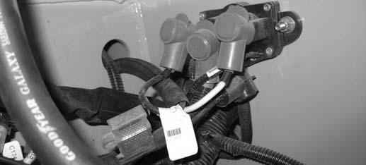
6.Drain water from the water separator: a.If water needs to be drained, position a suitable collection container underneath the water separator drain. b.Turn the fuel shut-off valve lever (P) on the water separator to the OFF position. c.Loosen drain plug (N) at the bottom of the water separator. Allow water to drain until indicator ring falls to the bottom of the cup. d.Tighten drain plug (N) and discard fuel/ water according to environmental laws. e.Turn the fuel shut-off valve lever (P) on the water separator to the ON position. Tighten vent plug (O), if it was loosened.

NOTE: If the water does not drain well, loosen vent plug (O).

7.Prime the fuel system by turning the ignition key to the ON postion without starting the engine for 30 seconds.
Caution
Do not use the starter motor to crank the engine to prime the fuel system. Damage to the engine starter motor, coils, pinion/ring gear could result.
4. Model 2500RT: Inspect the water separator (Fig. 137) for the presence of water: a.Position a suitable collection container underneath the water separator drain. b.Twist drain fitting (R) at the bottom of the water separator. Allow water to drain until flow stops. Twist drain fitting (R) back to it’s original position to close.
5. Models 1750RT/2100RT: Inspect the water separator (Fig. 137) for the presence of water:
IMPORTANT: Dispose waste fuel according to environmental laws. DO NOT pour fuel onto the ground or down a drain.
Changing Fuel Filter
Warning
NEVER service the fuel system while smoking, while near an open flame, or if the engine is hot.
Replace the fuel filter annually, or after every 500 hours of use.
IMPORTANT: The fuel filter change interval should be 250 hours when the available fuel has a sulfur content greater than 2000 ppm.
1.Perform the “Mandatory Safety Shutdown Procedure” on page18.
2.Wait until the engine has cooled. See “Maintenance and Service Safety Practices” on page23.
NOTE: On Model 2500RT machines, the fuel filter is located under the ROPS/FOPS, on the left side beneath the fuel tank. On all other machines, the fuel filter is located on the left side of the engine.
3.On Models 1750RT/2100RT: a.Open the engine cover “Engine Access” on page121. b.Turn fuel shut-off valve lever (P, Fig. 137) on the water separator to the OFF position.

4. On Model 2500RT: a.Lift the ROPS/FOPS according to “Raising ROPS/FOPS” on page142.
5.Remove the fuel filter (Z, Fig. 138), using a filter wrench if necessary. Carefully clean the filter head mounting surface with a clean cloth.
NOTE: On Models 1750RT (Serial Numbers 131001 and Up) and 2100RT (Serial Numbers 241001 and Up), the fuel filter is accessed through the oil drain plug access panel (Fig. 123).
6.Apply a coating of clean diesel fuel on the new fuel filter gasket. Install the filter and tighten 3/4 rotation past the point where the gasket contacts the filter head.
7. Models 1750RT/2100RT: Turn shut-off valve on water separator to ON.
8. Model 2500RT: lower the ROPS/FOPS according to “Lower ROPS/FOPS” on page143.
9.Prime the fuel system by turning the ignition key to the ON postion without starting the engine for 30 seconds.

Caution
Do not use the starter motor to crank the engine to prime the fuel system. Damage to the engine starter motor, coils, pinion/ring gear could result.
Hydraulic System Maintenance WARNING
Never use your hands to search for hydraulic fluid leaks; use a piece of paper or cardboard to find leaks. Escaping fluid under pressure can be invisible and can penetrate the skin, causing serious injury. If any fluid is injected into your skin, see a doctor at once. Injected fluid MUST be surgically removed, or gangrene may result.
Checking Hydraulic Oil Level
Check the hydraulic oil level daily before starting the machine, or after every ten hours of use.
1.Park the machine on a level surface. Fully retract all hydraulic cylinders (lift arm down; bucket flat).
2.Perform the “Mandatory Safety Shutdown Procedure” on page18.
3.Wait until the engine has cooled. See “Maintenance and Service Safety Practices” on page23.
4.Open the engine cover “Engine Access” on page121.
5.Check the level of the hydraulic oil in the sight gauge (Y, Fig. 139) located in the right engine compartment wall. The oil level be in the middle of the sight gauge (A).
6.If the hydraulic oil level is low, use the accessory key (supplied with the ignition key) to unlock and open the hydraulic tank cover (H, Fig. 140), located on the top right of the machine next to the top engine cover. Lock tank cover open using pin (D).


Caution
Always prop the hydraulic tank cover open using pin (D). Severe injuries can result if the battery compartment cover falls on hands and/ or fingers.
Later Machines
Early Machines
7.Remove the hydraulic tank breaker/oil fill cap (P).
NOTE: On early machines, fill the hydraulic tank through oil filler (B). Slowly remove the hydraulic oil fill cap (B). Allow the pressure to escape before completely removing the cap.

8.Add hydraulic fluid if required. See “Fluids/ Lubricants Types and Capacities” on page33 for proper hydraulic oil grade and type.

IMPORTANT: Do not mix different types/grades of hydraulic fluids.
Reinstall and tighten the oil fill cap. Close and lock the hydraulic tank cover.
Changing Hydraulic Oil and Filter
NOTE: The hydraulic oil filter can be changed without changing the hydraulic oil or draining the hydraulic reservoir.
Change the hydraulic oil filter after the first 50 hours, and after 500 hours or 1 year of use thereafter.
Change the hydraulic oil if it becomes contaminated, after major repairs, and after 500 hours or 1 year of use.
1.Perform the “Mandatory Safety Shutdown Procedure” on page18.
2.Wait until the engine has cooled. See “Maintenance and Service Safety Practices” on page23.
3.Open the engine cover according to “Engine Access” on page121.
4.Position a waste oil collection container with a capacity of at least 83.5 L (22 gals.) underneath the hydraulic oil reservoir.
NOTE: The hydraulic reservoir drain plug is accessed from underneath the machine at the right rear corner.
5.Remove the hydraulic reservoir drain plug and allow the oil to drain completely.
IMPORTANT: Always dispose of hydraulic fluids according to environmental laws or take to a recycling center for proper disposal. DO NOT pour onto the ground or down a drain.
6.Remove the hydraulic oil return filter (D, Fig. 141), using a filter wrench of necessary. Carefully clean the filter head mounting surface with a clean cloth.
7.Apply a coating of clean oil on the new oil filter gasket. Install the filter and tighten 3/4 rotation past the point where the gasket contacts the filter head.
8.Re-install and tighten the drain plug.
9.Using the key, unlock and open the hydraulic tank cover (H, Fig. 140), located on the top right of the machine next to the top engine cover.
10.Remove hydraulic breather/oil fill cap (P or B, Fig. 140) and add hydraulic oil until the level reaches the middle of the sight glass (A, Fig. 142). Replace and tighten the hydraulic oil fill cap. Close the engine compartment.
NOTE: See “Fluids/Lubricants Types and Capacities” on page33 for proper hydraulic oil grade and type. Hydraulic oil capacity listed is approximate.
11.Start the machine. Cycle through all hydraulic functions several times to purge air from the hydraulic system. Shut down the machine according to “Mandatory Safety Shutdown Procedure” on page18.
12.Check the machine for hydraulic oil leaks. Correct any leaks as required.
13.Add oil to the hydraulic system as required until the level reaches the middle of the sight glass (A). Replace and tighten the hydraulic oil fill cap.
Hydraulic Hose Maintenance WARNING
Hydraulic hoses and connections must be inspected by a trained technician before the first use of the machine, and at least annually thereafter, for leaks and/or damage.
Leakages and damaged pressure hose/lines must be immediately repaired or replaced by an authorized service center.
Never use your hands to check for suspected hydraulic leaks. Always use a piece of wood or cardboard.
Leaks from hydraulic hoses or pressurized components can be difficult to see, but pressurized oil can have enough force to pierce the skin and cause serious injury.
Obtain immediate medical attention if pressurized oil pierces the skin. Failure to obtain prompt medical assistance could result in gangrene or other serious damage to tissue.
Always relieve hydraulic system pressure before performing any maintenance on the machine. Do not tighten leaking connections when the hydraulic system is under pressure.
Warning
Never weld or solder damaged or leaking pressure lines and/or screw connections. Always replace damaged hydraulic components.
Hydraulic hoses must be replaced every six years from the date of manufacture, even if they do not appear damaged. The date of manufacture (month or quarter and year) is indicated on hydraulic hoses. See Fig. 143.

Travel Motor Maintenance
Travel Motor Gearbox Oil
6.Rotate the travel motor gearbox 180° so the drain/fill hole plug (G, Fig. 144) opening is at the top.
7.Fill the travel motor gearbox with the correct grade and type oil. Fill to level (J, Fig. 144).

NOTE: Oil level will be visible at hole (H) when correct oil level is reached.
8.Clean and replace drain/fill hole and plugs (G and H). Tighten securely.
9.Test the drive system and check for leaks
Track Maintenance
Inspect the tracks daily for damage and wear.
Observe the following conditions to extend track life:
•Avoid traveling or turning on broken stone, jagged rock, metal or other material that could damage or cut the tracks.
Replace the travel motor gearbox oil if it becomes contaminated, after major repairs, after the first 150 hours of use and every 1000 hours or annually thereafter.
1.Park the machine with travel motor gearbox drain/fill hole plug (G, Fig. 144) at the bottom.

2.Perform the “Mandatory Safety Shutdown Procedure” on page18.
3.Position a waste oil collection container with a 1 quart/liter (+ 0.10 quarts/liters) underneath the drain/fill hole plug (G).
IMPORTANT: Always dispose of hydraulic fluids according to environmental laws or take to a recycling center for proper disposal. DO NOT pour onto the ground or down a drain.
4.Remove plug (H).
5.Remove drain/fill hole plug (G) and allow the oil to drain completely.
•Avoid traveling on riverbeds or areas with soft rocks that could become stuck in the tracks, which could cause damage to the tracks or cause the tracks to slip off.
•Avoid using the machine on the seashore. Sea salt can corrode the metal cores inside the tracks.
•Immediately wipe any spilled fuel, oil, salt or chemical solvents off of the tracks, as these substances can corrode the coupling in the metal cores in the tracks, causing corrosion and peeling
•Avoid traveling on freshly paved roads or on hot surfaces (e.g. fires, metal sheets exposed to direct sunlight, etc.). Hot surfaces can damage the lugs or cause irregular wear.
•Avoid moving earth in area where the tracks may slip, which can cause excessive lug wear.
Track Replacement
Warning
Keeps hands clear from between the track and the idler when installing tracks. Crushing of body parts and amputation can result.
1.With the machine running and the drive system not moving, remove tension cylinder stop (K, Fig. 145) on the side on the machine with the track to be replaced.

Later Models 1750RT/2100RT
Other Machines Similar
M
3.When the track tension cylinders are in the service (retracted) position, shut off the machine.

4.Raise the machine about 150 mm (6”), so the tracks are free to move.
Warning
Use solid support blocking. Never rely on jacks or other inadequate supports when maintenance work is being done. Never work under any equipment supported only by jacks.
5.Use a pry bar to pry/guide the old track at (R, Fig. 147) off the front idler wheel.
2.With the machine running and the drive system not moving, open the engine compartment. Press and hold the lock button (L, Fig. 146) on the track tension service switch, and press the top (M) of the switch to set the track tension cylinders into the service (retracted) position.

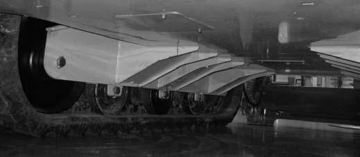
6.Using a hoist with a hook installed and a pry bar, lift/guide the old track at (T, Fig. 147) off the drive sprocket. Remove the old track.
7.Using a hoist with a hook, lift the new track at (T), and manoeuver the track under the rear idler wheel at (Q) using a pry bar and your foot.
IMPORTANT: Guides on the inside of the track must straddle the rear idler.
8.Place a block under the new track at (S), to hold the track against the bottom of the rear idler wheel.
9.Using a hoist with a hook and a pry bar, lift/ guide the new track at (T) onto the drive sprocket.
IMPORTANT: Lugs on the inside of the track must be fully engaged by drive sprocket (P).
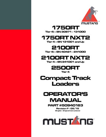
10.Using a pry bar (A, Fig. 148) and wedging blocks (U), pull/guide the new track at (R) over the front idler wheel, and under the bottom rollers. Carefully direct an assistant to start the machine and direct the assistant to operate the track drive slowly forward/back to work the track over the front idler wheel.
Warning
Keeps hands and feet clear from between the track and the idler/roller wheels when installing tracks. Crushing of body parts and amputation can result.
NOTE: Tie-down bracket (W) can be used as a lever point for prying the track into place over the front idler wheel.

IMPORTANT: Guides on the inside of the track must straddle the front idler and bottom roller wheels.
11.Make sure the new track is fully engaged around the idler and roller wheels, and in the drive sprocket, all the way around.
12.Remove any wedging blocks (U) that were used to guide the track.
13.Remove the block placed under the track at (S, Fig. 147).
14.The installed track should look similar to Fig. 149.
15.Start the machine, open the engine compartment and press the bottom of the track tension service switch (N, Fig. 150), to set the track tension cylinders into the operating (extended) position.


Later Models 1750RT/2100RT Shown; Other Machines Similar
17.Operate the track drive forward/back to ensure the track is properly seated. Adjust track positioning if necessary.
18.Remove blocking and lower the machine to the ground.
16.Once the track tension cylinder has returned to the operating (extended) position, re-install cylinder stop (K, Fig. 151).
General Lubrication
IMPORTANT: Use of lubricants not corresponding to manufacturer recommendations may invalidate warranty claims. Always dispose of waste lubrication oils and hydraulic fluids according to environmental laws or take to a recycling center for proper disposal. DO NOT pour fluids onto the ground or down a drain. Refer to the following figures for grease fitting locations. See “Fluids/Lubricants Types and Capacities” on page33 for proper grease specifications. Wipe dirt from the fittings before applying grease to prevent contamination. Replace any missing or damaged fittings. To minimize dirt build-up, avoid excessive greasing.
A – Back Lift Cylinder Grease Fittings (2)

B – Top Lift Arm Grease Fittings (2)
C – Front Lift Cylinder Grease Fittings (2)
D – Attachment Hitch Pivot Points (2)


– NOTE: Lubricate (D) from inside of pin.

E – Bottom Tilt Cylinder Grease Fittings (2)
F – Top Tilt Cylinder Grease Fittings (2)
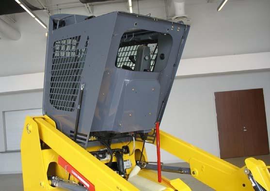
Tilting ROPS/FOPS
Tilting up the ROPS/FOPS provides access to hydraulic and electrical components.
Raising ROPS/FOPS WARNING
Always secure the ROPS/FOPS to the chassis with anchor bolts and washers (M, Fig. 153) before driving or using the machine.

Always close the cab door before tilting the ROPS/FOPS.
Stay clear from underneath the ROPS/FOPS as it is tilted.
Check ROPS/FOPS tilt component condition at regular intervals. Replace damaged or worn parts immediately.
1.Perform the “Mandatory Safety Shutdown Procedure” on page18.
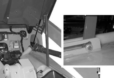
2.Remove anchor bolts and washers (M, Fig. 153) securing the front of the ROPS/FOPS to the chassis.
NOTE: Gas springs balance the ROPS/FOPS to aid raising and lowering.
3.On machines equipped with a cab, securely close and latch the cab door.
4.Close the engine cover.
5.Raise the ROPS/FOPS up as far as it will go (Fig. 154).
6.With the ROPS/FOPS fully raised, tilt prop bar (P Fig. 155) locks into the slot at the back of bracket (F), securing the ROPS/FOPS in the tilted position. Release the ROPS/FOPS to make sure it is locked in the raised position.
Warning
Make sure to raise the ROPS/FOPS as far as it will go so the tilt prop bar securely locks the ROPS/FOPS in the raised position. Never allow anyone under the ROPS/FOPS if it is not securely locked in the raised position with the tilt prop bar.
Lower ROPS/FOPS
1.Lift the ROPS/FOPS up slightly until tilt prop bar (P Fig. 156) clears the slot at the back of bracket (F). Push tilt prop bar (P) forward to allow the ROPS/FOPS to tilt forward and down.
2.Slowly and carefully tilt the ROPS/FOPS forward and down.
Caution
Stay clear from underneath the ROPS/FOPS as it is tilted down. Injury to limbs can result.
3.Secure the ROPS/FOPS to the chassis with anchor bolts and washers (M, Fig. 157). Torque anchor bolts to 75 lb.-ft. (102 Nm).
Warning
Always secure the ROPS/FOPS to the chassis with anchor bolts and washers (M, Fig. 157) before driving or using the machine.
Electrical System WARNING
Inspect and check the machine’s electrical equipment at regular intervals. Defects, such as loose connections or scorched cables much be repaired before using the machine.
Only use proper, original equipment fuses with the specified current rating. Turn off the machine immediately if there are any problems with the electrical system.
Work on the machine’s electrical system must be done only by a trained technician.
Battery WARNING
Before servicing the battery or electrical system, disconnect the negative cable from the negative battery terminal, or if the machine is equipped with a battery disconnect switch, turn the switch to the “OFF” position.
Explosive gas is produced while a battery is in use or being charged. Keep flames or sparks away from the battery area. ALWAYS charge the battery in a well-ventilated area.
Do not jump-start a frozen battery, or it may explode. A discharged battery can freeze at 10°C (14°F).
To prevent short circuits keep metal parts on your clothing and metal watchbands away from the positive (+) terminal of the battery.
Warning
Never lay a metal object on top of a battery, because a short circuit can result. Battery acid is harmful to skin and fabrics. If acid spills, follow these first-aid tips:
•if battery acid spills on any clothing, remove it immediately.
•If acid contacts skin, rinse the affected area with running water for 10 to 15 minutes.
•If acid contacts eyes, flood eyes with running water for 10 to 15 minutes. See a doctor at once. Never use any medication or eye drops unless prescribed by the doctor.
•To neutralize acid spilled on the floor, use one of the following mixtures:
•0.5 kg (1 lbs.) of baking soda in 4 L (4 qts.) of water.
•0.5 L (0.5 qts.) of household ammonia in 4 L (4 qts.) of water.
To access the battery, use the accessory key (supplied with the ignition key) to unlock (H, Fig. 158) and open the battery cover, located on the top left of the machine next to the top engine cover.


Caution
Always hold the battery compartment cover open when working on the battery. Use pin (D), if so equipped. Severe injuries can result if the battery compartment cover falls on hands and/ or fingers.
Using a Booster Battery (Jump-Starting)
Jump-start the machine according to “JumpStarting” on page83.
Fuses and Relays

IMPORTANT: Blown fuses indicate electrical system malfunctions. Determine what caused the fuse to blow and repair the problem before replacing the fuse.
Engine Compartment Fuses/Relays (Model 2500RT)

RelayCircuit
AHorn
BHVAC Blower
CAir Conditioning Condenser Fan
DWork Lights
EDrive, Tilt (Controller 2)
FWipers
GParking Brake Switch
HFuel Pump

IPower Relay, Ignition Switch, Dome Light
JEngine Start Relay
KPower-A-Tach® Relay
LGlow Relay
RelayCircuit
M15AHeadlights
N30AFuel Pump
O10A
Power/Relays, Main/Drive Logic Control Module
P10ATail Light, Backup Alarm, Radio
Table
Q20AHVAC Condenser Fan
R15A Interlocks, 2-Speed, Hydraglide™, Lift, Tilt (Controller 3)
S30AECU
T20AWork Lights
U20A Lift, Standard/High-Flow Aux. Hydraulic Controllers (Controller 1 & High-Flow Module)
V30AHVAC Relay
W10AAuxiliary Power Outlets
X10AParking Brake Relay, Power-A-Tach®
Y10AHorn
Z20AWipers
AA10A Start Relay, Flasher Controller, Hazard Lights
BB10AIgnition
CC15ATrack Tension, Self Level
DD10ADisplay, Joysticks, Seat/Door Switches
EE80A Power Relay, Ignition Switch, Dome Light
FF30APower-A-Tach® System Hitch
GG100AGlow Relay Fuse
Engine Compartment Fuses/Relays

Model 1750RT (Serial Numbers 131001 and Up)
Model 2100RT (Serial Numbers 241001 and Up)
Model 1750RT (Serial Numbers 131001 and Up)
Model 2100RT (Serial Numbers 241001 and Up)
Table 10: Engine Compartment Relays/Fuses
Fuse Rated Current / Resistance (A / Ω) Protected Circuit
A10Drive Logic Control, Tilt (Controller 2)
B15 Interlocks, 2-Speed, Hydraglide™, Float, High-Flow Auxiliary Hydraulics
C20 Lift, Standard Auxiliary Hydraulics (Controller 1)
D10 Park Brake, Power-A-Tach® Quick Attach System Hitch
E30HVAC Blower
F10Display, Joysticks, Seat/Door Switches
G 10 Ignition, Fuel Pump
H20HVAC Condenser Fan
I20Work Lights
J10Auxiliary Power Outlets
K20Wipers
L15Track Tension, Self Level
M10Horn
N10Beacon/Auxiliary Lights
Model 1750RT (Serial Numbers 131001 and Up)
Model 2100RT (Serial Numbers 241001 and Up)
O20Engine ECU
P20EGR Valve
Q120Ω Resistor, Oil Pressure Switch
R80Main Power (maxi)
S60Starter Solenoid (maxi)
T80Glow Plugs (maxi)
RelayCircuit
UEGR
VDrive, Tilt (Controller 2)
WHVAC
XWork Lights
YHorn
ZAC Condenser Fan
AAParking Brake Switch
BBWiper Motors
CCPower Relay
DDStarter Solenoid
EEGlow Plugs

Model 1750RT (Serial Numbers 131001 and Up)
Model 2100RT (Serial Numbers 241001 and Up)
Fuse/ Resister
Rated Current / Resistance (A /
) Protected Circuit
FF30APower-A-Tach® System Hitch
RelayCircuit
GGPower-A-Tach® Relay
Engine Compartment Fuses/Relays

Model 1750RT (Serial Numbers 131000 and Before)
Model 2100RT (Serial Numbers 241000 and Before)
Model 1750RT (Serial Numbers 131000 and Before)
Model 2100RT (Serial Numbers 241000 and Before)
Table 12: Engine Compartment Relays/Fuses

RelayCircuit
AWiper Motors
BParking Brake Switch
CWork Lights
DDrive, Tilt (Controller 2)
EFuel Injection Pump
FAir Conditioning Condenser Fan
GStart
HHVAC
IEngine Pre-Heat
Fuse Rated Current / Resistance (A / Ω) Protected Circuit
J15ATrack Tension, Self Level
K15AHeadlights
L10ARear Door, Beacon Lights, Radio
M20AWork Lights
N10AAuxiliary Power Outlets
O20AWipers
P120Ω Resistor, Oil Pressure Switch
Q20AFlasher Controller, Hazard Lights
R10ADisplay, Joysticks, Seat/Door Switches
S10AFuel Pump, Power Splice
T20AHVAC Condenser
Model 1750RT (Serial Numbers 131000 and Before)
Model 2100RT (Serial Numbers 241000 and Before)
U10A Power/Relays, Main/Drive Logic Control Module
V10A Interlocks, 2-Speed, Hydraglide™, Lift, Tilt (Controller 3)
W20A Lift, Standard/High-Flow Aux. Hydraulic Controllers (Controller 1 & High-Flow Module)
X10A Brake Lights, Power-A-Tach® Quick Attach System Hitch Switch
Model 1750RT (Serial Numbers 131000 and Before)
Model 2100RT (Serial Numbers 241000 and Before)
Fuses Under ROPS/FOPS
Model 1750RT (Serial Numbers 131000 and Before)
Model 2100RT (Serial Numbers 241000 and Before)
Model 1750RT (Serial Numbers 131000 and Before)
Model 2100RT (Serial Numbers 241000 and Before)
Fuse Box Cover Shown Removed
Fuse/ Resister
Rated Current / Resistance (A / Ω) Protected Circuit
Y30APower-A-Tach® System Hitch Z60AEngine Pre-heat


Fuse Rated Current (Amp) Protected Circuit
AA40AHVAC Relay Fuse (Maxi 3)
BB80A Power Relay, Ignition Switch, Dome Lights Fuse (Maxi 2)
CC60AStarter Solenoid Fuse (Maxi 1)
DDN/AStarter Solenoid Relay
EEN/AMain Power Relay
Control Modules
Electrical control modules are located on the chassis under the ROPS/FOPS.
Multi-function Control Module
Multi-function control module (N, Fig. 170) provides the following control functions:
•Horn
•Fuel sender input
•Starter and parking brake interlock logic
•Hydraulic and air filters indicator inputs

•Two-speed travel logic
•Safety logic control
•Lift arm float and Hydraglide™ logic
Lift Arm and Standard Auxiliary Flow Control Module
Control module (P) includes outputs for lift arm and standard auxiliary hydraulics flow function.
Engine Control Module (ECU)
Control module (Q) controls engine control logic and error reporting.
Main/Drive Control Module
Main/drive control module (R) provides the following control functions
•Logic for travel drive and main control valve
•Bucket function
•Transmission, control valve and controller communication error codes broadcast output
Long-Term Storage
If storing the machine for a long period (longer than 2 months), perform the procedures in this section.
Before Storage
1.Wash the entire machine. Treat vinyl surfaces in the operator’s compartment with a vinyl protectant.
2.Perform all steps for long-term engine storage according to the engine operation manual.
3.Lubricate all grease fittings. See “General Lubrication” on page141.
4.Check all fluid levels and top-off as necessary.
5.Add a fuel stabilizer to the fuel system according to the fuel supplier’s recommendations.
6.Remove and fully charge the battery. Store the battery in a cool, dry location.
7.If the machine will not be operated for a month or longer, apply grease to all exposed hydraulic cylinder rod areas or retract all cylinders so rod exposure is minimized. Apply grease to any remaining rod areas.
8.Protect against extreme weather conditions such as moisture, sunlight and temperature. Fill the engine coolant system with the proper mix of antifreeze and water as required for expected temperatures according to “Coolant Compound Table” on page37.
IMPORTANT: Contact your dealer for additional storage preparation information if the machine will be stored in an environment where temperatures could range below -42°C (-44°F), and/or above 49°C (120°F).
After Storage
1.Replace and re-connect the battery.
2.Perform all steps for returning the engine to service according to long-term engine storage section in the engine operation manual.
3.Check V-belt tension.
4.Check all fluid levels and top-off as necessary.
5.Start the engine. Observe all indicators. If all indicators are functioning properly and reading normally, move the machine outside.
6.When outside, park the machine and let the engine idle for at least 5 minutes.
7.Shut off the engine and walk around machine. Make a visual inspection looking for evidence of leaks.
Air Conditioning Maintenance
Test air conditioning function weekly. Reduced air conditioning function could indicate a low refrigerant level. Low refrigerant or refrigerant leaks can cause air conditioning compressor overheating and failure.
IMPORTANT: Air conditioning system should be filled only by technicians trained in the air conditioning fill processes.
Air Conditioning Filters
Check the condition of the air conditioning filters every 250 hours of use and replace if necessary.
NOTE: Extreme or dusty/dirty conditions may require more frequent maintenance.
Cab Air Filter
1.Slide the operator’s seat as far forward as it will go to provide access to the cab wall behind the seat.


2.Remove fasteners (A, Fig. 171) securing filter grilles (S) to the cab wall. Remove and discard the old filter elements.


3.Insert new filter elements and secure with grilles (S) and fasteners (A). Make sure the filter elements are completed seated in the openings and the grilles are firmly seated flush to the cab wall.
Outside Air Intake Filter
1.Perform the “Mandatory Safety Shutdown Procedure” on page18.
2.Remove hardware (F, Fig. 172) securing the outside air filter cover (G). Remove cover (G).
3.Remove old air filter (H)
4.Install new air filter (H), positioned so the side with the metal grate (Z) faces in.
5.If necessary, apply foam strips (I) to the outside edges of new air filter to provide a good seal.
6.Replace cover (H) and secure with hardware (F)
Windshield Washer Reservoir

The windshield washer reservoir (R, Fig. 173) is located inside the engine compartment. Check the windshield washer reservoir level daily before starting the machine and fill if necessary.

Later Machines
Early Machines
IMPORTANT: Fill the windshield washer fluid reservoir with clean tap water only. Add a cleaning agent if required. Add antifreeze to the water in cold weather.
Final Shutdown / Decommissioning
IMPORTANT: Dispose of all materials properly. Used oils/fluids are environmental contaminants and may only be disposed of at approved collection facilities. Never drain any oils/fluids onto the ground, dispose of in municipal waste collection containers, or in metropolitan sewer systems or landfills. Check state and local regulations for other material disposal requirements.
If the machine will no longer be used as intended, shutdown, decommission and dispose of it according to the valid regulations.
Before Disposal
1.Shutdown the machine according to valid regulations regarding proper shutdown.
2.Park the machine on level, dry ground. Ensure the surface can support the weight of the machine. Ensure the location is protected against access by unauthorized persons.
3.Move the throttle to the low-idle position and allow the engine to cool for approximately 2 minutes.
4.Shut off the engine.
5.Move the lift/tilt control(s) to verify that the controls do not cause movement of the lift arm or hitch.
6.Raise the arm rests/safety bars to apply the parking brake and lock out the hydraulic controls.
7.Switch off all electrical switches.
8.Unfasten the seat belt, remove the ignition key and take it with you.
9.Ensure the machine cannot be operated after shutdown until further disposal.
10.Ensure no environmentally hazardous materials, fluids and/or fuel can escape the machine. Specifically check for leaks from the engine, the hydraulic system and the coolant system.
11.Ensure the machine poses no dangers in the place where it is standing.
12.Remove any dirt and/or debris from the engine compartment, the chassis and the cylinder rod surfaces.
13.Remove the battery
14.Lock the cab door, the storage compartment, the battery and hydraulic filler compartments and the engine compartment. Remove the key(s) and take it/them with you.
Machine Disposal
Make sure all materials are disposed of in an ecologically sound manner.
Recycle the machine in accordance with the current state of the art at the time of recycling. Observe all accident prevention regulations.
Dispose of all parts at the at the recycling sites specific to the material of the part. Take care to separate different materials for recycling.
Maintenance Log
Log all maintenance as it is performed in the following table.