5 minute read
Reassembly


NOTE: Use bolt torque chart that follows to tighten bolts as steering unit is assembled.
Bolt Torque Chart Bolt Size Torque Value
M10 4.8 kg•m (35 ft. lbs.) 3/8 - 16 NC 4.8 kg•m (35 ft. lbs.)
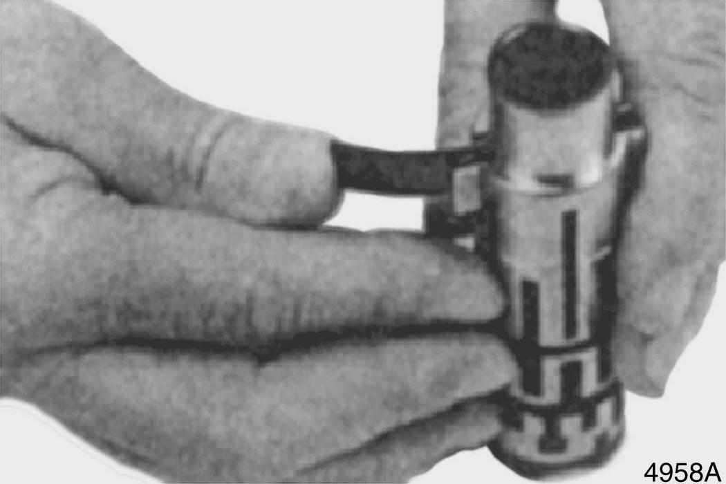
1. Install springs in spool slot. See Figure 28.
Springs must be positioned as shown in
Figure 29.
2. Position springs so that amount of spring protruding out of spool is equal on both sides. See Figure 30.
Figure 28
Figure 29
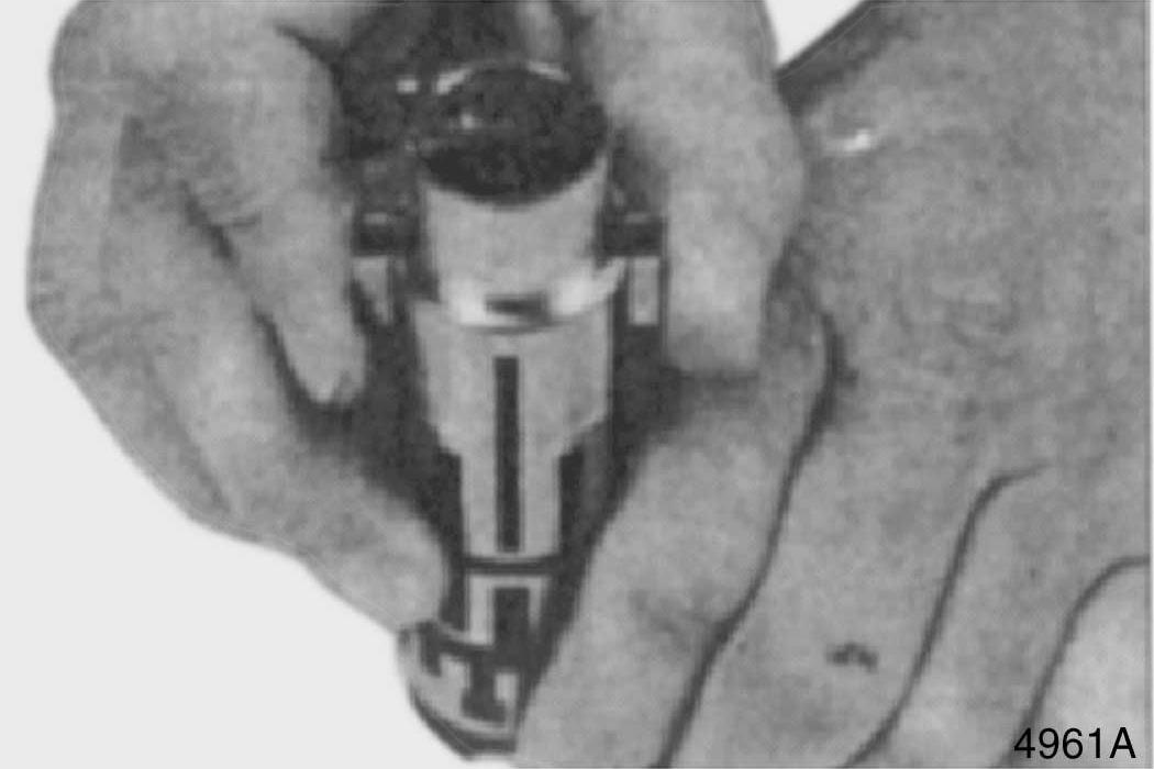
Figure 30
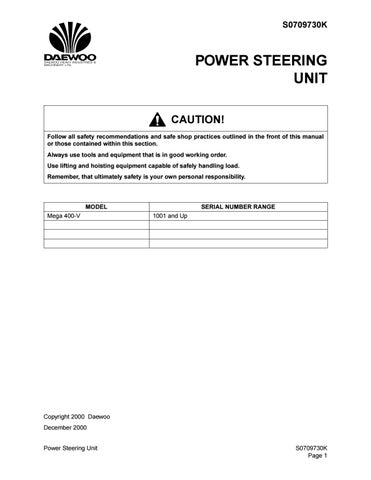
3. Insert spool into sleeve. See Figure 31.
Use care so that sleeve and spool are correctly assembled. The spring slot in sleeve must align with spring slot in spool.
Also, one of the T shaped slots (A) in the spool must align with one of the small holes (B) in sleeve. See Figure 32.
4. Center springs in sleeve. See Figure 33.
Figure 31
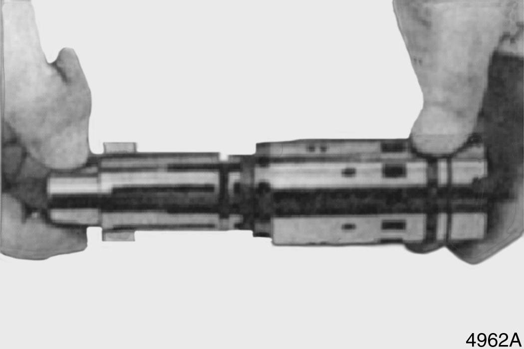
Figure 32
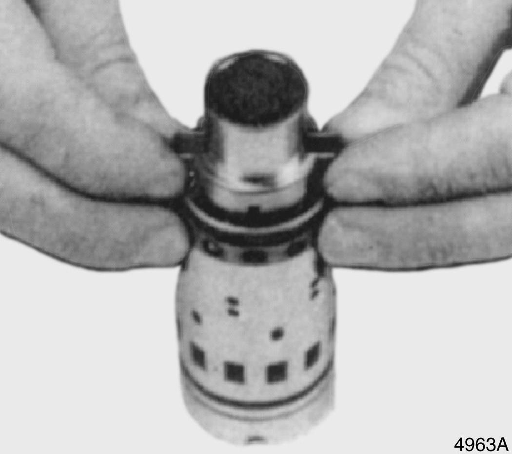
Figure 33
5. Install seal ring on sleeve. See Figure 34.
Burnish seal ring with a smooth object until seal does not protrude past diameter of sleeve.
6. Rotate seal ring. See Figure 35. It must rotate freely without resistance.
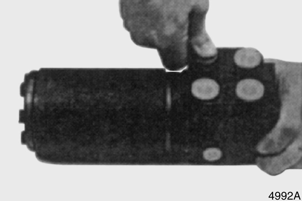
7. Turn sleeve 180°. Install cross pin into sleeve and spool. See Figure 36.
Figure 34
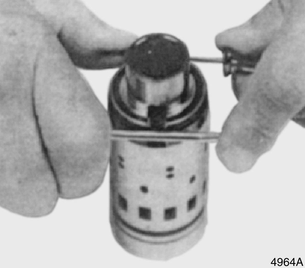
Figure 35
Figure 36
8. Install two thrust washers and thrust bearing over end of spool. See Figure 37.
The sequence of the parts installation is shown in Figure 38.
9. Oil O-ring and backup ring and then install them on an O-ring assembly tool. See
Figure 39.
Reference Number Description
1 Thrust Washer 2 Thrust Bearing 3 Thrust Washer 4 Spool 5 Sleeve
Figure 37
Figure 38
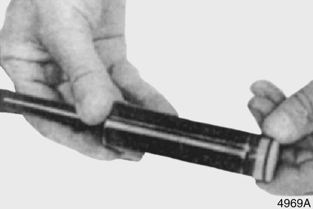
Figure 39
11. Use assembly tool to install O-ring and backup ring into bore. See Figure 41.
12. Unbolt housing from stabilizing base. Hold housing in a horizontal position. See
Figure 42. Insert sleeve and spool into bore.
Figure 40
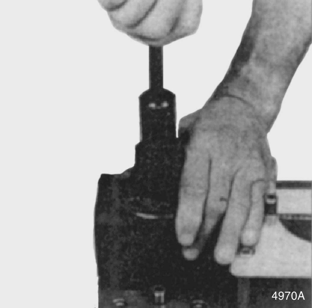
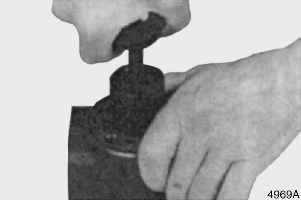
Figure 41
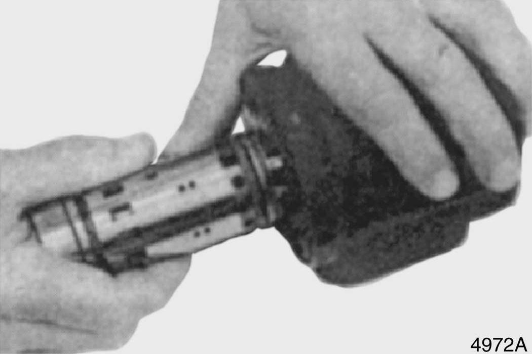
Figure 42
13. The sleeve will push the O-ring and backup ring into correct position. See
Figure 43.
14. Bolt housing back into stabilizing base.
See Figure 44.
15. Insert ball into hole. See Figure 45.
Figure 43
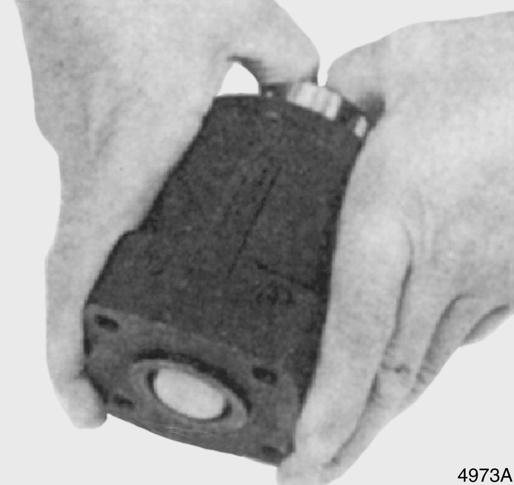
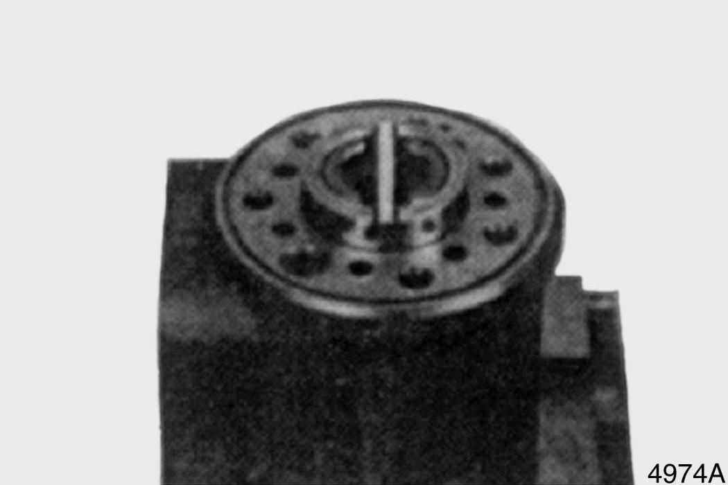
Figure 44
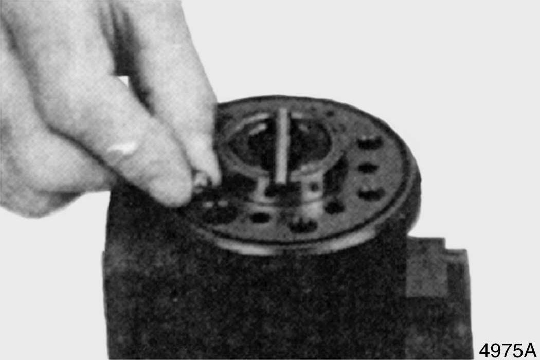
Figure 45
16. Install threaded bushing into hole that ball was placed into. See Figure 46. Lightly tighten bushing. The top of the bushing must be lower than the surface of housing.
17. Lubricate O-ring with 20 weight mineral oil and install it in groove. See Figure 47.
18. Install middle plate onto housing. See
Figure 48. Be sure to properly align plate holes with holes in housing.
19. Lubricate O-ring with 20 weight mineral oil and install it in groove. See Figure 49.
Figure 46
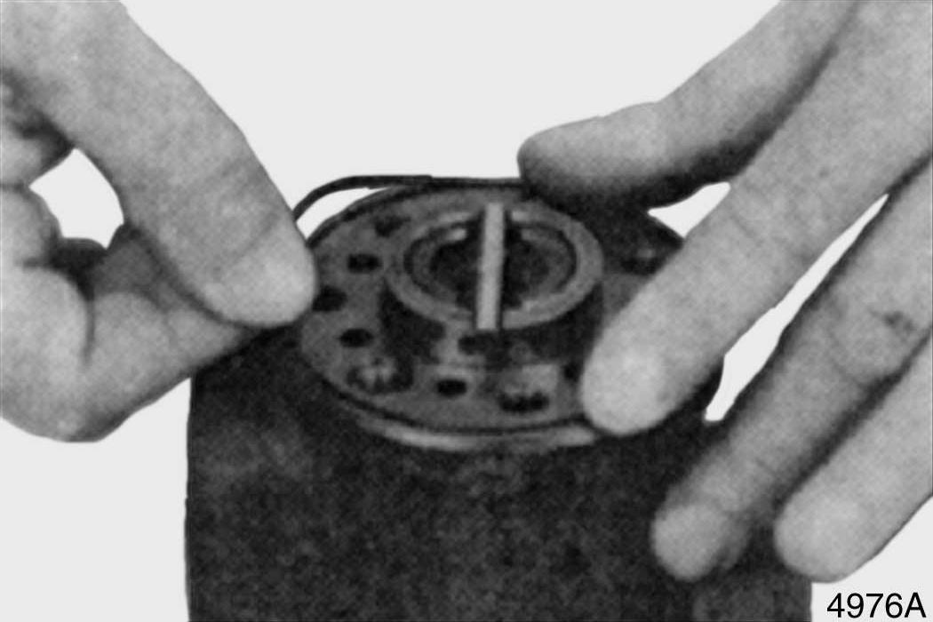
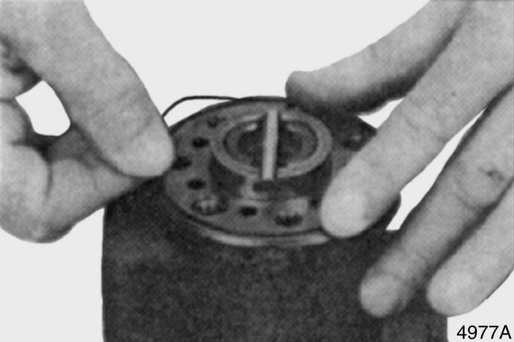
Figure 47
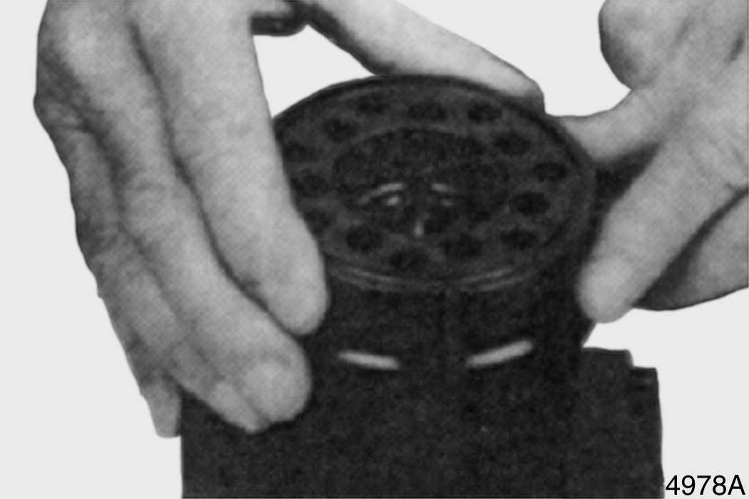
Figure 48
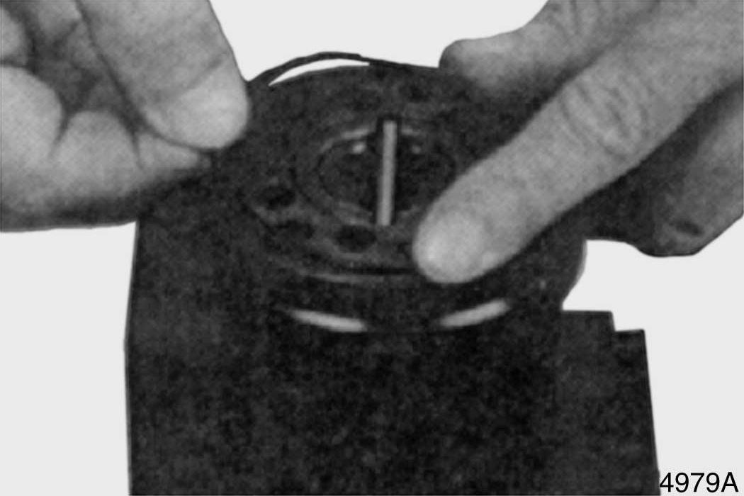
Figure 49
20. Install distributor plate. See Figure 50. Be sure to properly align plate holes with holes in middle plate.
21. Install shaft into bore of housing. See
Figure 51. Position slot in shaft to engage cross pin.
22. Position rotor so that cross pin is located between two teeth as shown by position of screwdriver. See Figure 52.
Figure 50
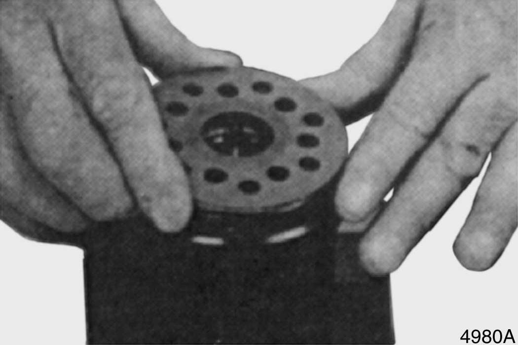
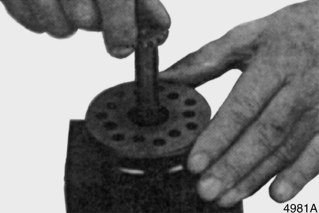
Figure 51
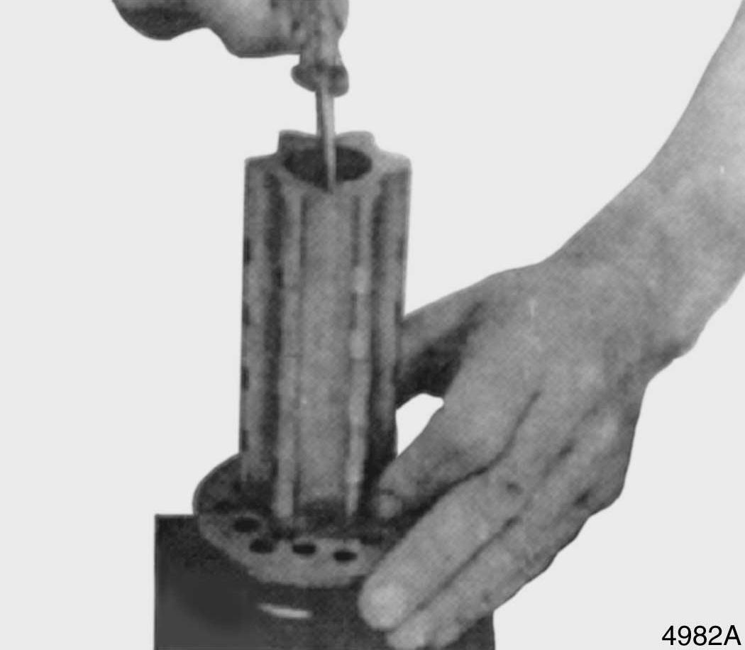
Figure 52
23. Lubricate two O-rings with 20 weight mineral oil and install them in grooves of cylinder gear. Slide cylinder gear into position on housing. See Figure 53.
24. Use a bolt to align holes in cylinder gear with bolt holes in housing. See Figure 54.
25. Install spacer bushing. See Figure 55.
Remove bolt that was installed in previous step (If equipped.).
OSPL 630:1 = 3.8 mm (15, Figure 5)
OSPL 800 (16, Figure 5)
OSPL 1000 (16, Figure 5)
NOTE: Refer to parts manual for our unit to determine if these parts are installed.
Figure 53
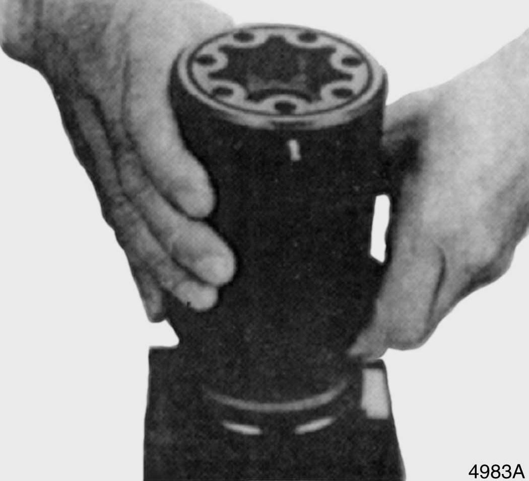
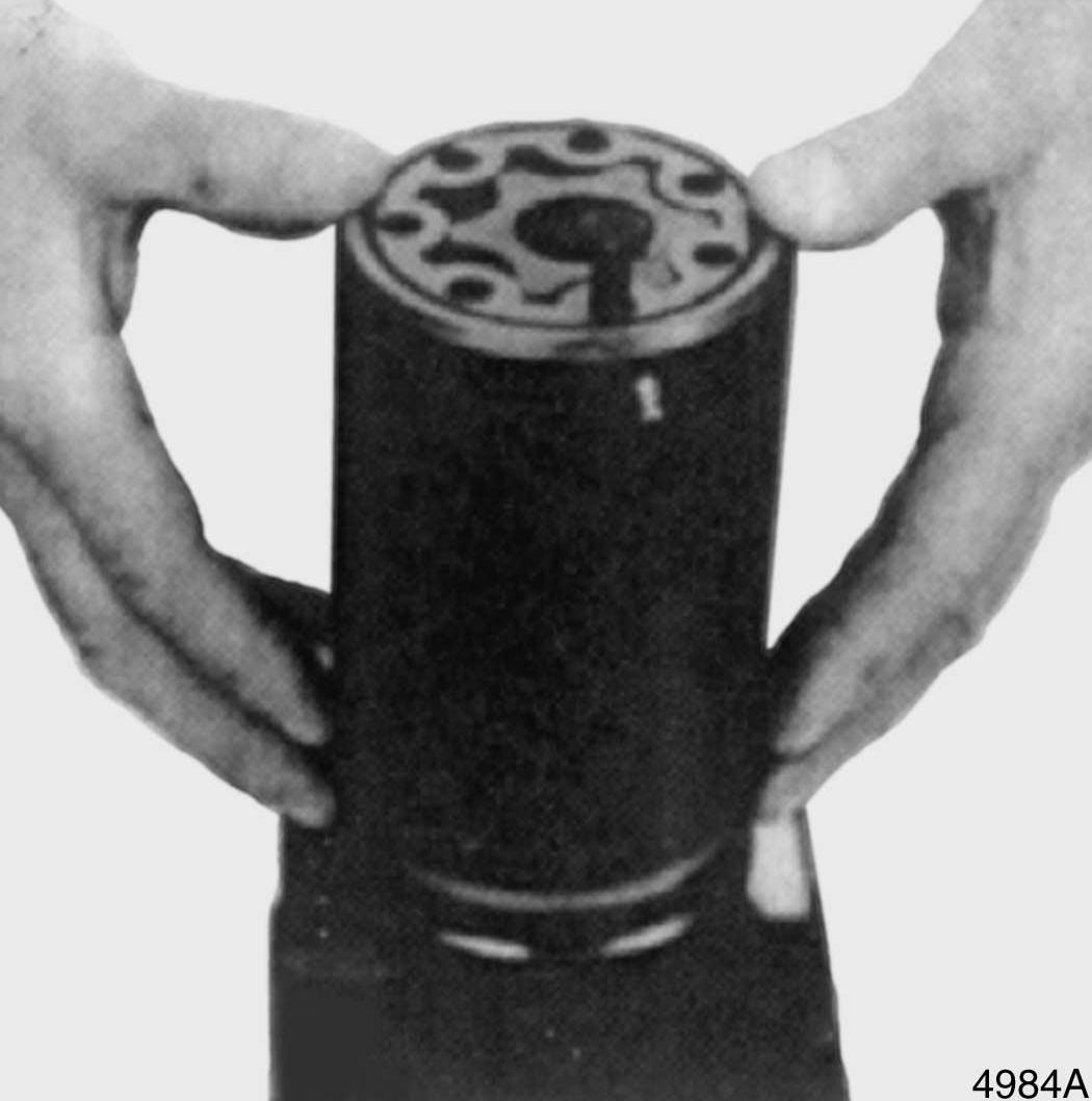
Figure 54
Figure 55
26. Use a screwdriver to install OSPL 800 and 1000 spacers (If equipped.). See Figure 56.
NOTE: Refer to parts manual for our unit to determine if these parts are installed.
27. Install end cover. See Figure 57.
28. Install a washer and roll pin into hole shown in Figure 58.
29. Install six remaining bolts and tighten them. See Figure 59. Cross tighten bolts and roll pin to 48.1 Nm (35 ft lb).
Figure 56
Figure 57
Figure 58
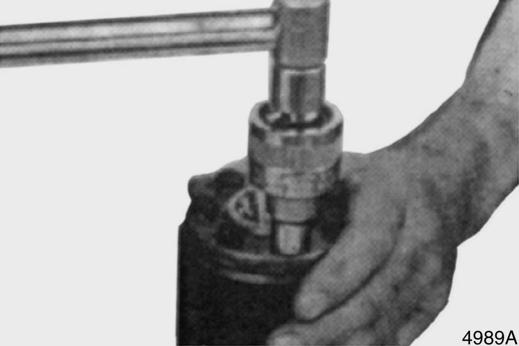
Figure 59
30. Turn steering unit over and work from opposite side. Set dust seal in position on housing. See Figure 60.
31. Use a seal driver and a plastic hammer to install dust seal. See Figure 61.
32. Install plastic plugs to prevent dirt from entering steering unit. See Figure 62.
Figure 60
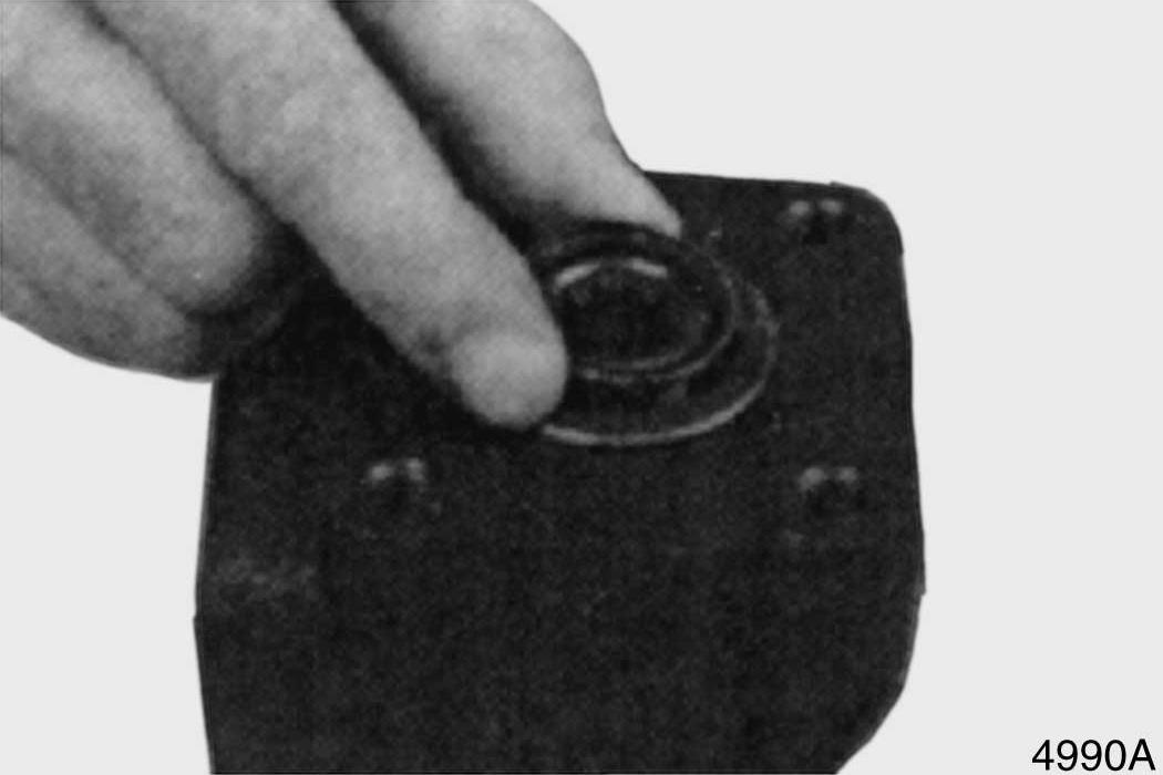
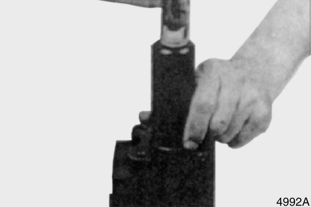
Figure 61