1 minute read
Permanent displays


Driver's area controls
Permanent displays
Permanent displays Permanent display, left-hand side
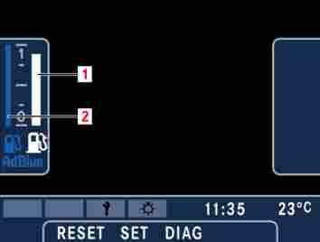
M54.00-1719-71 The permanent display field on the lefthand side contains the fuel gauge. The fuel gauge comprises two vertical bar graphs. Left bar graph (2) shows the fill level in the AdBlue tank, right bar graph (1) shows the fill level in the diesel tank.
Permanent display, right-hand side
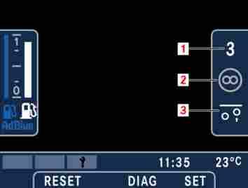
M54.00-1724-71 The permanent display field on the righthand side contains gear indicator (1), brake indicator (2) and driving characteristics (3): Gear indicator (1) shows the selected gear. If a transmission malfunction has occurred, the gear indicator turns red or yellow, depending on the severity of the malfunction. Brake indicator (2) represents the braking functions of the bus. As different functions compete for the same symbol position, only the most important braking function is displayed at any one time. A white symbol indicates active braking, grey is used for an inactive or preselected brake (example: retarder preselected). Field (3) represents conditions that may affect the driving characteristics of the bus. As different functions compete for the same symbol position, only the most important function is displayed at any one time.
Permanent display, lower
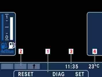
M54.00-1723-71 The upper area of the lower permanent display is used to display various status indicators (red alert, yellow alert, service notification and bulb defect) (2). The “Bulb defect” status indicator is dis-