1 minute read
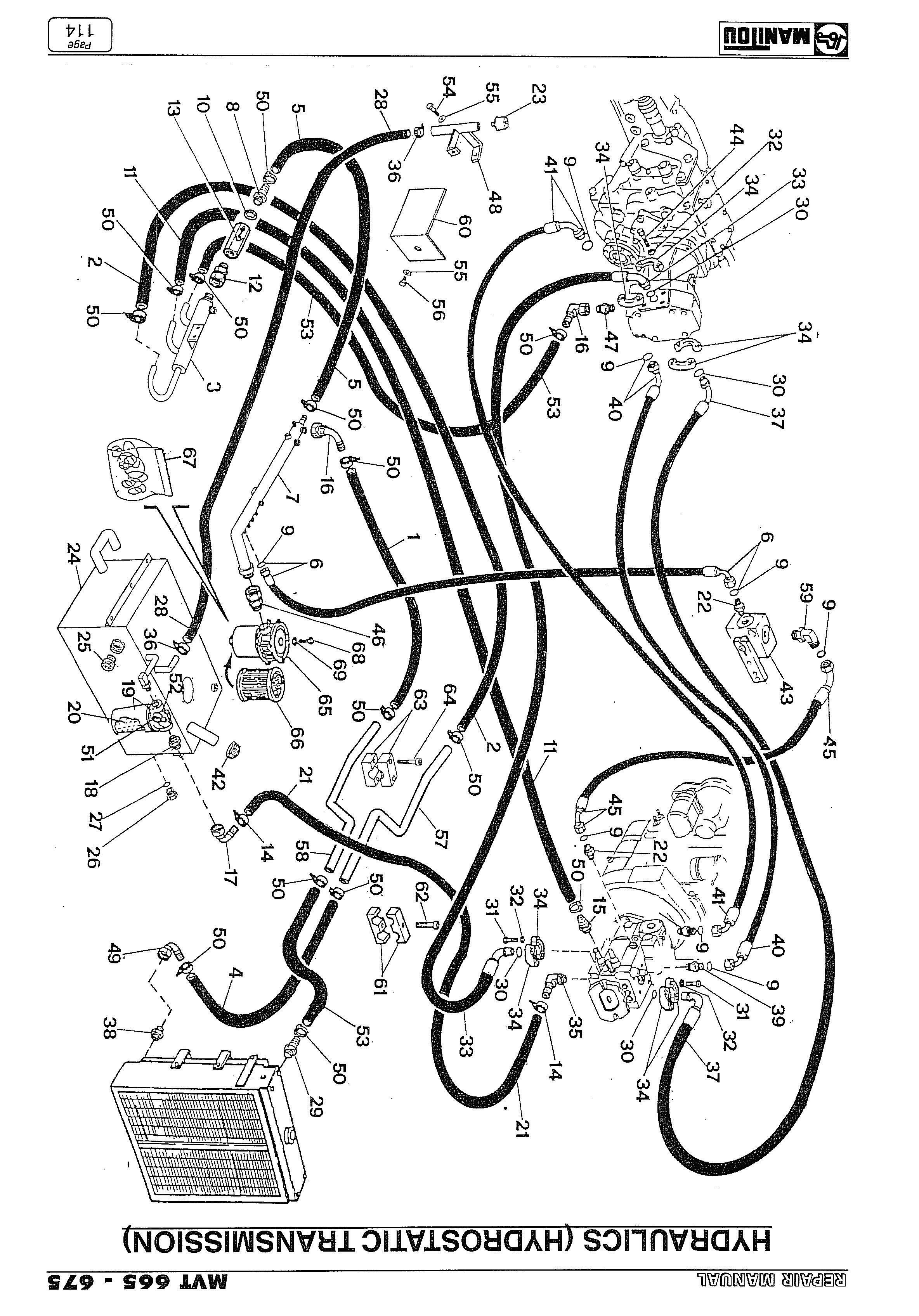
Hydraulics (Main circuit


The radiator is now free of all fastenings; it can be removed from the chassis from below upwards by hooking it to a bridge crane.
Fig. 48
1
2 1
- Park the truck on flat ground.
- Raise the telescopic arm to its maximum height.
- Stop the engine.
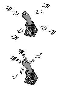
- Remove depressurise from the hydraulic circuit using the controls in the cab (see Fig. 49) with the ignition key turned in contact “I”.
- Refit the ignition key in contact “0” with the engine switched off.
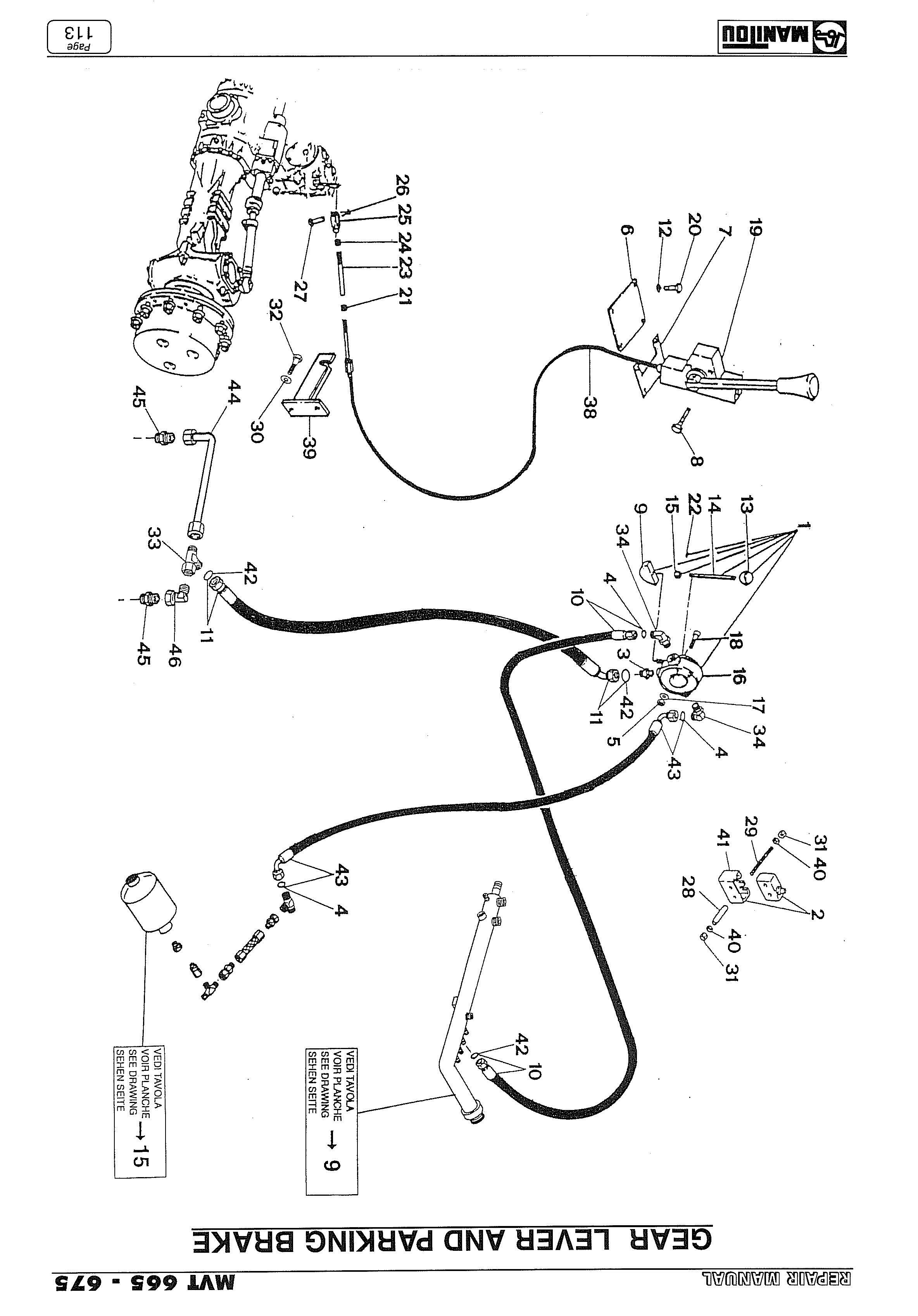
- Disconnect the delivery and exhaust hydraulic pipes of the distributor and pump piloting (Ref. 1, 2, 3-ILL. 50).
- Disconnect the control hydraulic piping of the distributor (Ref. 1, 2, 3, 4, 5, 6, 7, 8-ILL. 51) and steering (Ref. 9, 10-ILL. 51).
- Disconnect the cylinders feed pipes (Ref. 1, 2, 3, 4, 5, 6, 7, 8-Fig. 52).
- Loosen the screws locking the distributor to the chassis (Ref. 4-Fig. 50).
Fig. 49
2
Fig. 50 3
4
1 2 3 4
Fig. 52
5 6 7 8
3 4 2 1 1
Fig. 51
10
9
56 7 8
ADJUSTMENT SCREW PLATE
MICROSWITCH
REAR AXLE SAFETY SWITCH PIN
ELASTIC SPRINGS
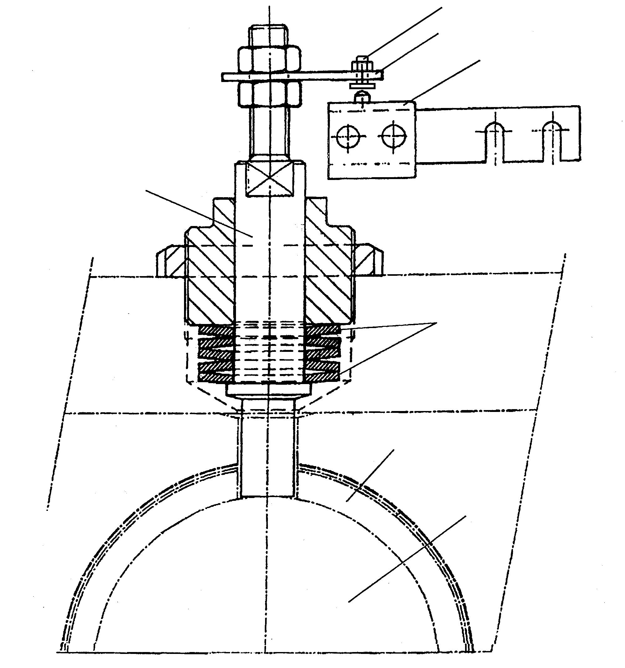
BUSHING
REAR AXLE PIN
ADJUSTMENT
1) The special shape of the rear axle bushing allows these small manouvres. 2) Movement between the frame and axle presses against the microswitch which activates the safety system indicator and alarm in the event of machine overload, stopping the hydraulic movements. 3) Adjustment of the system involves loading the arm (as shown in the loading diagram in the guide to “Use and maintenance”) and calibrating the microswitch in such a manner that the safety system is activated in the above mentioned loading conditions.