1 minute read
Trouble-shooting


- With the internal combustion engine operating at medium-high revolution (2000 min-1), perform end-of travel with the arm raised. - Ensure that the pressure gauge “M” shows 275 bar (3929 PSI).
Adjusting, if necessary:
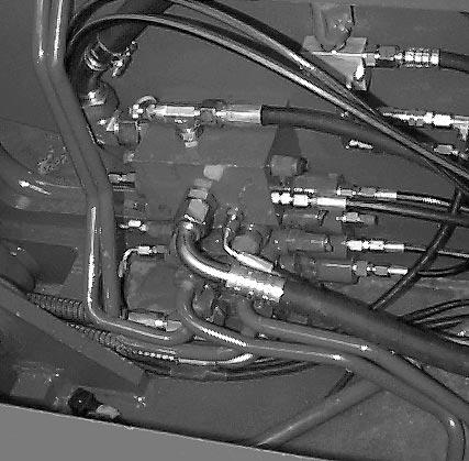
use the pressure cut-off valve “T” fitted on the load sensing distributor unlock the lock nut using a 17 mm wrench slowly loosen using a 6 mm socket head wrench, until the pressure gauge “P” shows a reading of 275 bar (3929 PSI) tighten the lock nut
NOTES :
Respect the safety regulations during checking and calibration. Calibration corrections, if necessary, must only be made at operating temperature.
Five pressure test connections are used for checking the pressure of the various circuits of the hydraulic system : (Fig. 1 / 2 / 3 / 4 / 5).
The valves are adjusted in the following manner :
- remove the valve cap - loosen the lock nut using a 17 mm wrench. - adjust to the required value, using a slot screw driver on the adjustment screws turning the adjustment screw clockwise increases the operating pressure turning the adjustment screw anticlockwise decreases the operating pressure
The machine’s hydraulic movements are adjusted in the following manner :
A) The pressure of the anti-impact valve of the compensation cylinder, at the bottom, must be 290 bar (4143 PSI).
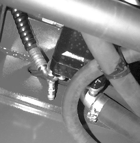
Connect the 0-600 bar pressure gauge (0-8700 PSI) to the quick coupling located to the right of the frame at the bottom of the compensation cylinder (Fig. 3).
Swing the fork-holder completely backwards (forks upwards), slowly lower the arm to read the calibration pressure.
Adjust the valve on the distributor if necessary (Ref. 2-Fig. 6) .
Fig. 1
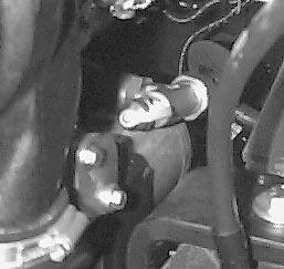
Fig. 2
Fig. 3
Fig. 5
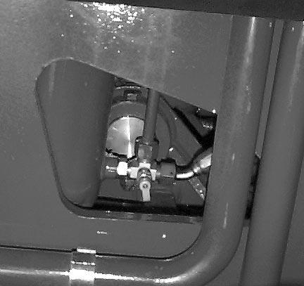
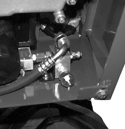
Fig. 4