3 minute read
HITCH OPERATION


Connecting Implement to Hitch
To connect an implement to the hitch, use the following procedure:
NOTE: Be sure the tractor and implement are on level ground.
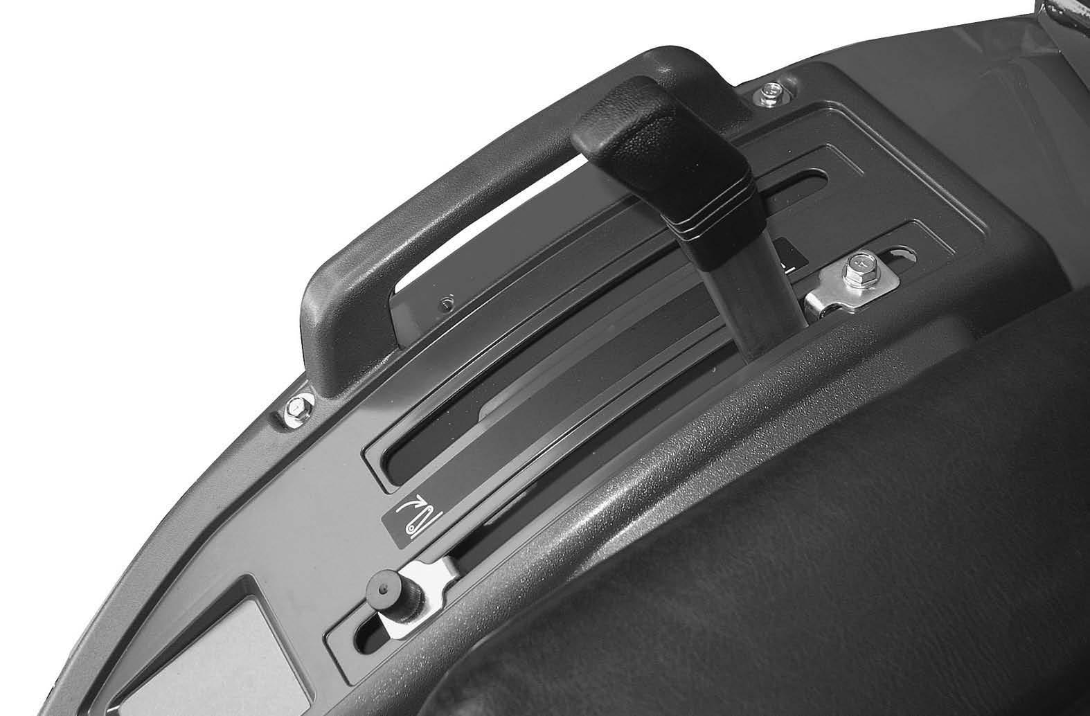
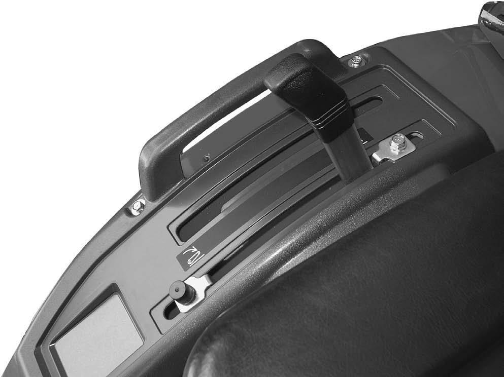
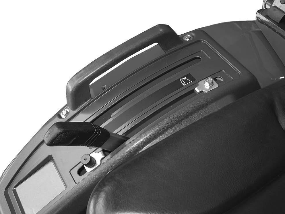
1. Put the drawbar in the storage position.
2. Slowly move the tractor backwards to the implement.
3. When the hitch points on the tractor and implement are in the correct position, stop the tractor.
4. Apply the park brake and stop the engine.
5. Connect the implement to the Upper and Lower Links.
6. A djust the Upper and Lower Links as necessary. See Hitch System Adjustments in this manual.
Disconnecting Implement from Hitch
To disconnect an implement from the hitch, use the following procedure:
NOTE: Be sure the tractor and implement are on level ground.
1. Stop the tractor completely and apply the park brake.
2. Disengage the PTO, lower the implement to the ground.
3. Gear Drive: Place the gear shift and range shift levers in Neutral.
Hydrostatic Drive: Release the speed lock lever, and place the range shift lever in Neutral.
4. Stop the engine and remove the key from the key switch before leaving the tractor
5. Disconnect the implement from the hitch.
NOTE: Be sure the tractor and implement are stable and free from any tendency to roll over
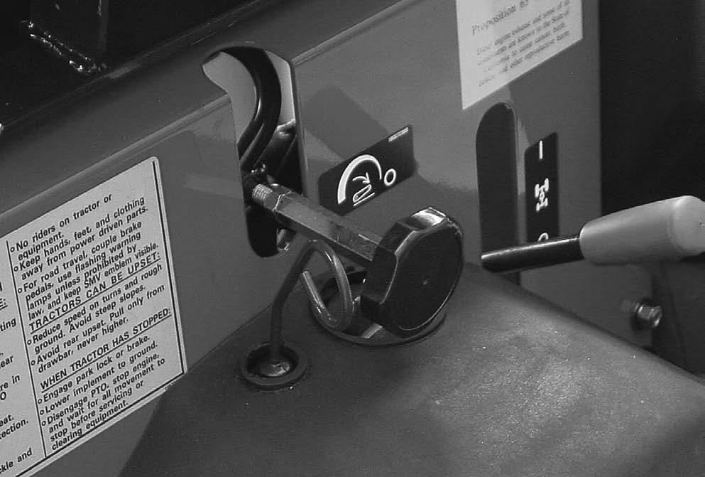
Hitch Control Lever
HITCH CONTROL LEVER
The hitch control lever is used to raise or lower the implement mounted to the three point hitch. To raise the hitch, move the lever to the rear. To lower the hitch, move the lever forward. Adjustable stops are provided for use whenever it is desirable to return the hitch control lever to the same operating position.
HITCH CONTROL LEVER
IMPORTANT: The position of the raise stop should not be set so rearward that a insufficient free play of the lift arms is available at the highest position when hitch control lever is moved until the lever is reached to the raise stop.
Hitch Lowering Speed Adjustment
To adjust the hitch lowering speed, use the following procedure:
1. M ove the hitch control lever forward to lower the implements.
2. T urn the hydraulic flow control knob to adjust the lowering speed. Turn the knob counter clockwise to increase the lowering speed. Turn the knob clockwise to decrease the speed or lock the hitch.
3. After adjusting the speed, raise the hitch and then lower it to check the speed.
NOTE: When transporting the tractor on the road with the implement mounted on the three point hitch, always set hydraulic flow control knob to the LOCK position.
IMPORTANT: Never park a tractor with an implement in the raised position. Moving the hitch control lever forward will lower the implement even though the engine is not running. If it is necessary to service the implement in the raised position, use jack stands to safely block the implement in place. Put the hydraulic flow control knob in the LOCK position.
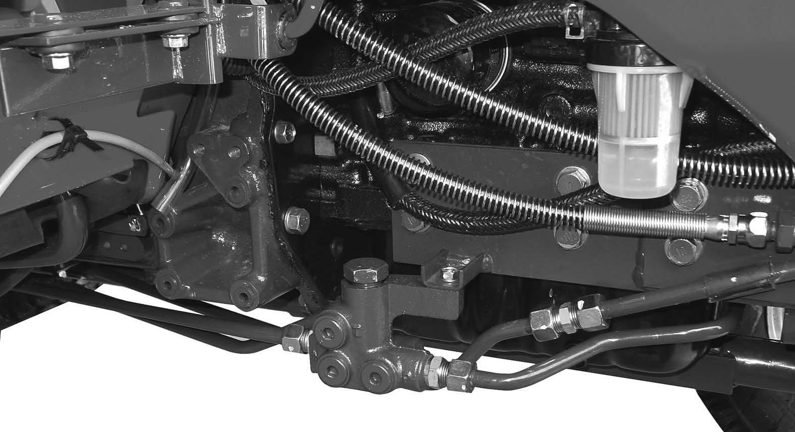
Hydraulic Block
A hydraulic block is located on the right side of the tractor. This block can provide an external hydraulic circuit for loader use or other applications. See your dealer.
IMPORTANT: Never park a tractor with an implement in the raised position. Moving the hitch control lever forward will lower the implement even though the engine is not running. If it is necessary to service the implement in the raised position, use jack stands to safely block the implement in place. Put the hydraulic flow control knob in the LOCK position.
IMPORTANT:
Remove the Plug P when the loader and the hydraulic block are used. Installing plug 1 to the Rc1/4. (tightening torque 21to29N-m{15to21Lbft}) (Do not close the port in the hydraulic block when there is no plug 1.)
When Remote attachment is not installed, remove plug1. Afterwards, install Plug P. (tightening torque 49to58.8N-m{35to44 Lbft})
When the above is neglected, the hydraulic apparatus will be disadvantaged Plug 1 is provided by the Loader manufacturer.
Adding Fluid after Connecting Cylinders and Hoses
Operate the engine at a moderate idle speed. Set the stroke stop at the yoke end of the cylinder rod to provide maximum stroke. Then operate the cylinder in both directions about five times at least by moving the control lever up and down.
This will fill the cylinder and hoses with fluid and remove the air from the system. Fill the cylinder completely, stop the engine and check the fluid level with the transmission dipstick.
Add sufficient, clean specified fluid to bring the oil up to the proper level. See TRANSMISSION AND HYDRAULIC LUBRICATION in this manual.
NOTE: If any of the hydraulic units are removed and replaced for any reason, check the oil level and add the specified fluid to the transmission to bring the oil up to the proper level.
When remote cylinders are connected to the hydraulic system, cycle the control lever about five times to remove air from the cylinder and hoses. With air in the system, raised equipment can drop accidentally and cause personal injury or machine damage.
Hydraulic oil or diesel fuel leaking under pressure can penetrate the skin and cause infection or other injury.
To Prevent Personal Injury:
Relieve all pressure, before disconnecting fluid lines. Before applying pressure, make sure all connections are tight and components are in good condition. Never use your hand to check for suspected leaks under pressure. Use a piece of cardboard or wood for this purpose. If injured by leaking fluid, see your doctor immediately.
The implement should be lowered to the ground before uncoupling of the remote hydraulic hoses.
Lower or block elevated implements and other attachments before servicing or when leaving the equipment.


