1 minute read
Switches


1. Ignition Key Switch
This is a key operated 3-way rotary switch located on RH side of steering column cover. It operates in clockwise direction and the positions are as follows:
1. OFF
2. IGNITION: This Position gives a readiness to the electrical circuit for operating plough lamp switch, brake light switch and turn signal switch. This puts ON the supply to instrument cluster and readiness to the electrical circuits for operation of light switch.

3. START: Turning the key to this position activates the starting circuit for starting the engine. When released, the key springs back to ignition position.
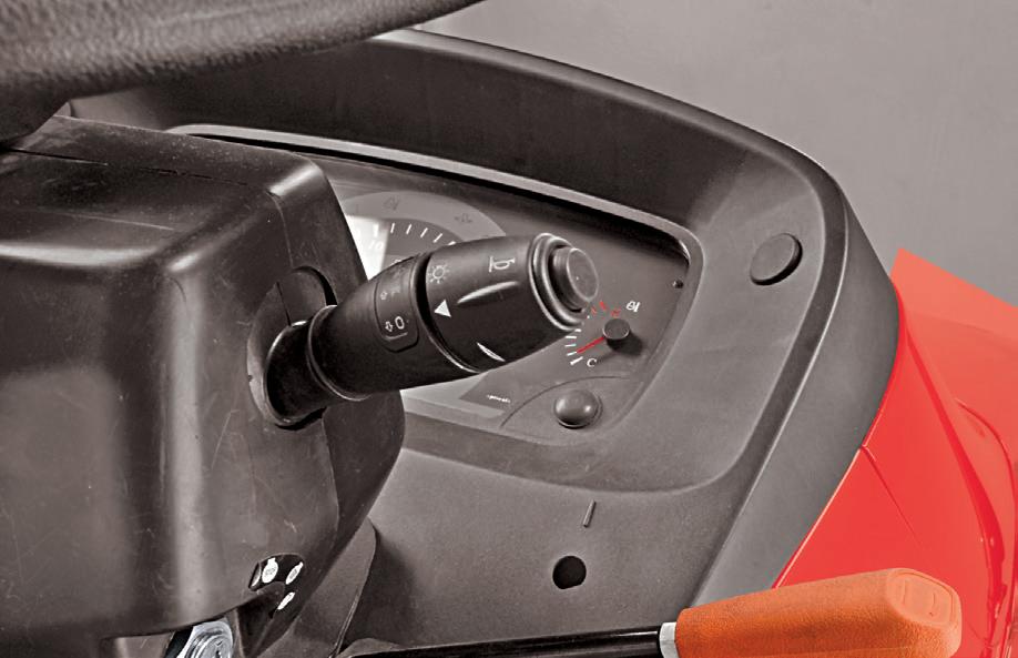
2. Steering Column Mounted Combination Switch (A)
This is multi-functional switch mounted on steering column. It consists of following operation switches.
1. Light Control
2. Dipper
3. Turn Signal
4. Horn
3.1 Light Switch
This is 3-way rotary switch. The operations are as follows:
1. Off
2. Illuminates instrument cluster illumination lamp and position lamps.
3. Illuminates low/high beam of head lamp in addition to the position lamp with respect to the position of the dipper.
3.2 Dipper Switch
This is a 3 way lever switch. It operates in up and down direction and the operations are as follows.
Center : Operate Low beam of Headlamp
Down side : Operate High beam of Headlamp
Up side : Passing through (Momentary switch)


3.3 Turn Signal Switch
This is 3-way rotary lever switch. It operates in front and forth direction and the positions are as follows.
Center : OFF
Forward : Operates left turn signal lamp
Rearward : Operates right turn signal lamp
3.4 Horn (B)
This is push button switch (B). Pressing this switch will enable the horn and releasing it will disable the Horn.