
3 minute read
Draft Control - Operation


Draft Control
As the draft of the implement varies due to irregularities of ground contour, soil texture, or pitching of the tractor, the load on the top link of the three point linkage will vary. These changes are transferred through the internal mechanism into hydraulic valve movement.
By means of the top link, the draft control system reacts not only when the top link is in compression, as is usually the case, when plowing, but also when the top link is in tension, as with shallow working implements. An increase in implement draft will increase the compression or reduce the tension on the top link and the system will go to lift. Conversely, a decrease in implement draft will cause the system to go lower.
Due to setting of the draft control lever, the load required to maintain the valve in the hold position is governed. Therefore, the load the tractor has to pull is maintained irrespective of ground contour, soil conditions, or the pitching of the tractor.
The lever is moved Forward to deepen the implement and Rearward to shallow it.
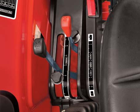
Setting the Draft Control
1.Move the PC lever (D) to its forward most position.
2.Move the position control stop screw (C) to the front of the quadrant and lock it.
3.Lift the implement off the ground by pulling the PC lever back to upper limit.
4.Lower the implement into work by moving the PC lever to its forward most position. The faster the lever is moved forward the quicker the implement will drop.
5.Move the tractor slowly in forward direction. When the implement has reached the desired working depth, move the draft control lever (A) rearward, until the linkage begins to lift, due to the load on top link. This will be the position of the lever for that particular depth in a particular type of ground.
6.Having obtained a desired setting move DC Stop screw (B) until it touches the DC lever (A) and lock it in this position.
When the soil texture remains constant, the implement weight is partially carried on the three point linkage. Therefore, proportion of the implement weight is transferred to the tractor rear wheels to improve traction. When a condition arises which causes an increase in draft, the system will lift and all the weight of the implement will be transferred to the tractor rear wheels to provide maximum traction. As soon as the draft returns to normal, the system goes to lower position and the situation returns to its former condition.
When the front wheels of the tractor drop into a furrow, the tendency for the implements is to lift out of the ground. As the implement lifts, the draft decreases and the system goes lower to maintain the pre-set depth. If the rear wheel drops into a furrow, the reverse will occur. Thus under all operating conditions, the “Vary-Touch” system provides maximum traction and constant implement depth.
Do not transport or attach equipment when the hydraulic system is in Draft Control. Use Position Control for these operations. Always lower hydraulic equipment to the ground before stopping the Tractor.
Under No Circumstances must the Draft Control Lever be used to Lift the implement to its uppermost Position. To do so will cause overheating of the system. All movements into and out of the soil must be made by using the Position Control lever.
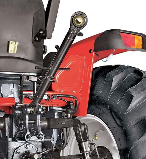
Toplink
It is used to attach the implement and control its inclination front-to-rear with respect to ground. The distance between its two ball-joints can be increased or decreased by rotating the turn-buckle as follows,
1.Loosen the lockplate (A).
2.Clockwise rotation of turn buckle will increase the distance.
3.Anti-clockwise rotation will decrease the distance.
4.Tighten the lockplate (A) after desired adjustment.

Top link implement end has provision for mounting CAT-I & CAT-II implements.
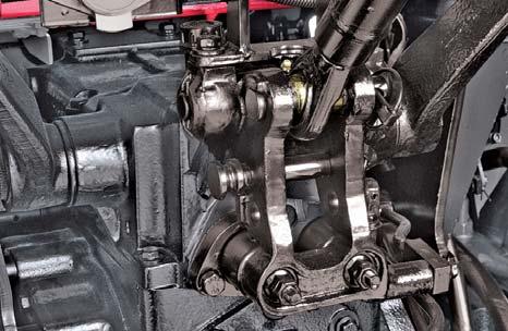
Draft Sensing Bracket
Draft sensing bracket transfers the toplink force to the draft sensing mechanism. It has three holes (B), (C) and (D) for hitching the toplink.
Maximum achievable depth of implement increases as the toplink is shifted from top to lower holes.
Top Hole (B):Attach toplink to hole (B) where draft sensing function is not required.
Centre Hole (C):Attach toplink to hole (C) where medium to Low draft sensitivity is required.

Lower Hole (D):Attach toplink to hole (D) where very high draft sensitivity is required.
Contact your Mahindra dealer to understand hitching position of toplink for specific implements used by you.
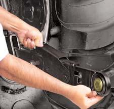
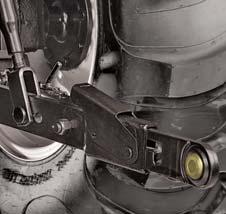
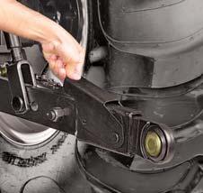
Telescopic Lower Links
Telescopic Lower Links are provided for ease of hitching the implement as follows,
1.Slowly back tractor into position to align the lower links with implement pins.
2.Park tractor safely.
3.Press the bracket (E) in lower link and pull link (F) to extend as needed.
4.Connect lower links to the implement. Sit on operator’s seat and start engine.
5.Back tractor until each lock lever snaps and secures each lower link in the lock position.


