2 minute read
AUXILIARY HYDRAULIC (optional


Your machine has two types of auxiliary hydraulic circuits. One circuit is for single flow equipment, such as hydraulic breakers. The second circuit is for single flow or double flow continuous flow equipment, or double flow equipment such as crushers. Consult your authorized LBX Link-Belt distributor for instructions on how to select the correct pressure for the optional tool. Hydraulic breaker configuration
STEP 1
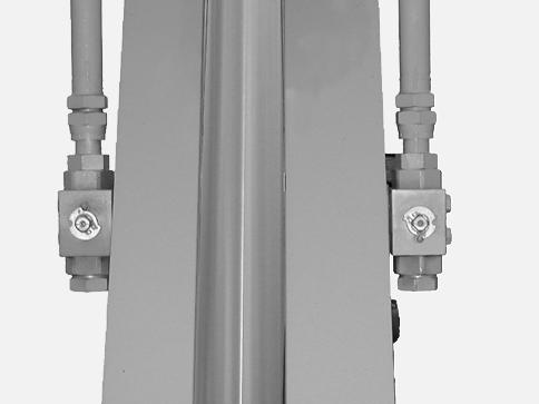
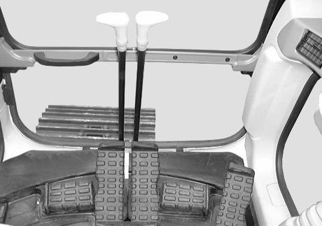
A24690 Using a hexagonal wrench, place the supply valves in “O” (open) position. See “Optional tool supply valves” in the “Controls/Instruments/Accessories” Section. STEP 2 STEP 3
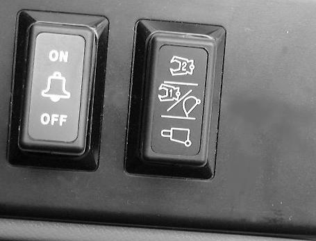
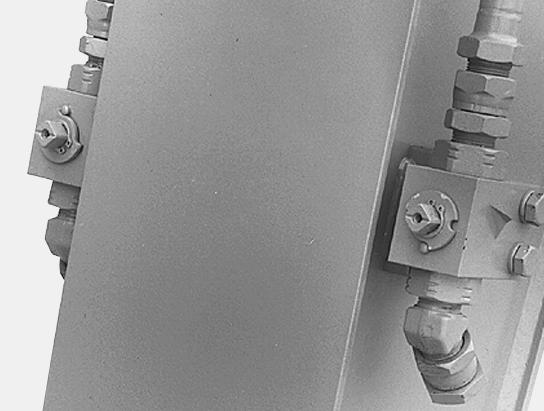
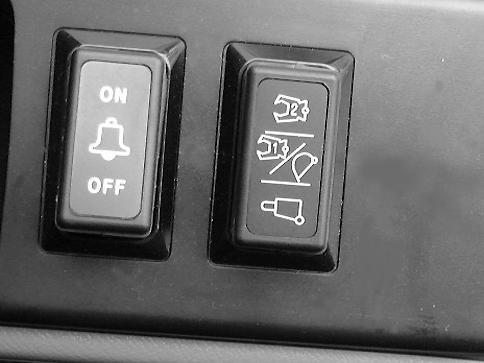
CD00E072 Tilt the control on the left-hand arm to the right for hydraulic breaker operation. STEP 4
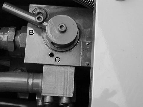
1
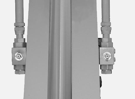
CD00E070 Remove the screw (1), place the flow selector valve in position (B) and then install the screw (1).
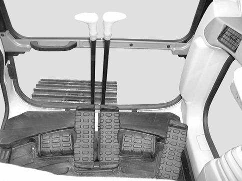
CD00E012 Use the control pedal to operate the hydraulic breaker.
STEP 5 STEP 6
BS00M135
CD00E082 When removing the hydraulic breaker, place the supply valves in “S” position (closed) and plug the orifices.
CD00E072 Tilt the control to the central position.
Double flow crusher configuration
STEP 1
A24690 Using a hexagonal wrench, place the supply valves in “O” (open) position. See “Optional tool supply valves” in the “Controls/Instruments/Accessories” Section. STEP 2 STEP 3
CD00E072 Tilt the control on the left-hand arm to the left for crusher operation. STEP 4
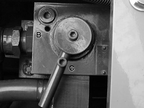
1
CD00E071 Remove the screw (1), place the flow selector valve in position (C) and then install the screw (1).
CD00E012 Use the control pedal to operate the crusher.
STEP 5
CD00E082 When removing the crusher, place the supply valves in “S” position (closed) and plug the orifices. STEP 6
CD00E072 Tilt the control to the central position.
SINGLE FLOW CRUSHER CONFIGURATION
STEP 1
A24690 For the crusher, use a hexagonal wrench to place the supply valves in “O” (open) position. See “Optional tool supply valves” in the “Controls/Instruments/Accessories” Section. STEP 2
CD00E071 The flow selector valve does not require adjustment. STEP 3
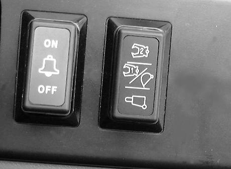
CD00E072 Make sure the control on the left-hand arm is in central position. STEP 4
CD00E012 Use the control pedal to operate the crusher. STEP 5
CD00E082
When removing the crusher, place the supply valves in “S” position (closed) and plug the orifices. 116