9 minute read
SYSTEMS DISPLAY AND CONTROL PANEL


4 5 6 1 2 3
BD00J056
WARNING: The display panel indicates the machine’s condition and alerts the operator quickly of any abnormalities by means of lamps indicators or buzzers.
WARNING: All changes in travel speed should be made while the machine is stopped. Always stop the machine to make a shift change.
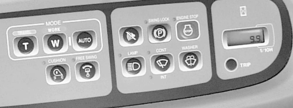
NOTE: Clean the display panel with a soft, dry cloth. Do not use solvents. 1.TRAVEL SPEED SELECTOR - This is a push button for changing from high speed to low speed . A confirmation message appears on the indicator (4).
Low speed : Select this speed to travel on slopes, rough ground or soft terrain. 210 LX and 240 LX , 0 to 2.1 mph (3.3 km/h) High speed : Select this speed to travel on hard, flat ground in good terrain conditions. 210 LX and 240 LX , 0 to 3.4 mph (5.5 km/hr) NOTE: When starting the engine, low speed is automatically selected. NOTE: When the hydraulic system is overloaded and the machine is in High speed, the machine automatically shifts down to Low speed. The system automatically returns to High speed as soon as the hydraulic system is no longer overloaded. 2.WORK MODE SELECTOR - This push button allows one of three working modes to be selected. “S” (standard) mode for ordinary duties; “H” (heavy) mode for hard work or when there is an increase in work load and “L” (lift) mode for precision work requiring lower operating speed. Confirmation of the mode selected is displayed on the indicator (5). NOTE: The selector will not function when “Auto” mode (3) is selected. NOTE: When starting the engine, “H” (Heavy) mode is automatically selected.
3.AUTO MODE SELECTOR - Select Auto-Mode to obtain the optimum operating mode , between “S” and “H” modes, for reduced fuel consumption.
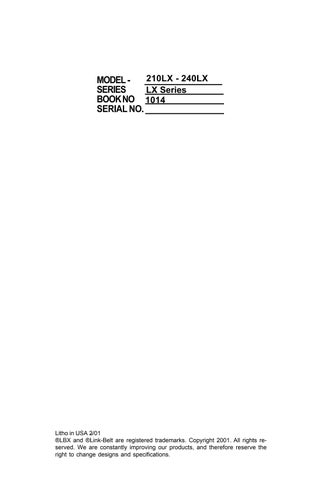
The confirmation (Auto) will be displayed on the indicator (5). Press the button again to come out of “Auto” mode, “H” (heavy) mode will then automatically be selected. 4.TRAVEL SPEED INDICATOR - This indicator displays a sign showing the travel speed selected with button (1). 5.WORK MODE INDICATOR - This indicator displays the initial of the working mode selected by the Button 1.
The letter “S” appears to indicate selection of “S” (standard) mode.
The letter “H” appears to indicate selection of “H” (heavy) mode.
The letter “L” appears to indicate selection of “L” (lift) mode.
“Auto” will be displayed to confirm that “Auto” has been selected with button. 6.ENGINE IDLE SPEED INDICATOR - This indicator displays the type of engine idle speed selected with the control on the right-hand control lever. See
“Right-hand control lever” (item 5).
“ON”: Auto Idle
“OFF”: One Touch Idle
SYSTEMS DISPLAY AND CONTROL PANEL
7
8 9
CD00E008
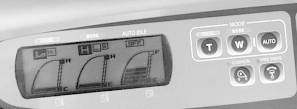
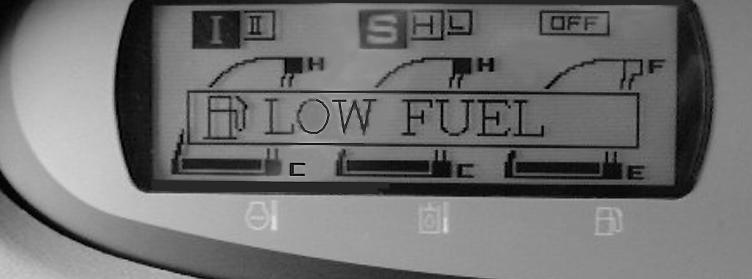
7.ENGINE COOLANT TEMPERATURE INDICATOR - Temperature changes are reflected by an increase or decrease in the number of luminous horizontal bars. Zone “C” indicates that the engine coolant temperature is low. If the luminous horizontal bars reach zone “H”, the audible alarm device sounds and the message “Over Heat” is displayed (see item 10). If the temperature does not drop, shut down the engine, remove the starter switch key and find the cause of the problem. 8.HYDRAULIC FLUID TEMPERATURE INDICATOR - Temperature changes are reflected by an increase or decrease in the number of luminous horizontal bars. Zone “C” indicates that the hydraulic fluid temperature is low. If the luminous horizontal bars reach zone “H”, the audible alarm device sounds and the message “Over Heat” is displayed (see item 10). Stop the engine, remove the starter switch key and find the cause of the problem. 9.FUEL LEVEL INDICATOR - The quantity of fuel is represented by the number of luminous horizontal bars. Zone “F” shows that the fuel tank is full. If the horizontal bars reach zone “E” the audible alarm device sounds and the message “Low Fuel” is displayed (see item 10).
IMPORTANT: Do not wait until the fuel tank is completely empty before refilling or it will be necessary to bleed the fuel circuit.
SYSTEMS DISPLAY AND CONTROL PANEL
10
CD00E009
10.MESSAGE DISPLAY SCREEN - As you operate the machine, this screen will display symbols and messages which change to keep you informed of the machine’s condition. The symbols and messages are listed below along with brief explanations. NOTE: It is possible to change the language configuration for the messages displayed. See your authorized LBX Link-Belt distributor.
ENG. PRE HEAT - This message shows that the engine needs pre-heating. As soon as the engine reaches working temperature, the audible alarm device will sound. AUTO WARM UP - This message shows that engine temperature is automatically rising to operating temperature. It disappears once the engine has reached operating temperature or when the engine idle speed selector, the throttle control button or a control lever is operated. See item 3 under “Righthand control arm”. ENG. IDLING - This message shows that the engine idle speed selector has been operated and that the engine is running at idle speed. See item 5 under “Right-hand control arm”. POWER UP - This message shows that maximum attachment power has been automatically requested.
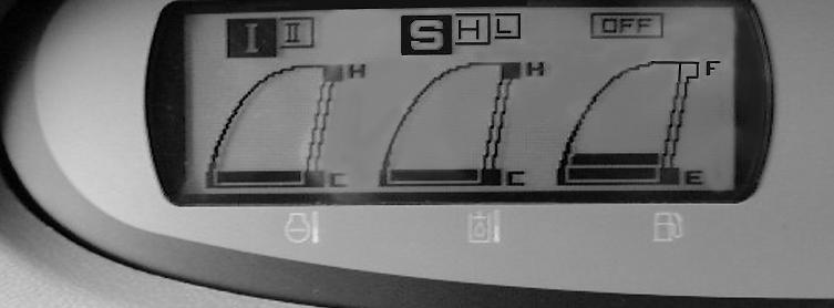
SERVICE DUE - This message shows that 500 hours servicing is due. The message will appear five times for a minute upon starting the engine. See the “Servicing Intervals” Section. LOW FUEL - This message shows that the level of fuel in the fuel tank is low and that fuel must be added. The audible alarm device also sounds.
SYSTEMS DISPLAY AND CONTROL PANEL
10
CD00E009
LOW COOLANT - This message shows that the engine coolant level is low. The audible alarm device also sounds. Shut down the engine, remove the starter switch key, allow the system to cool down and then check the coolant level in the expansion reservoir and the radiator. See “Cooling System” in the “Lubrication/Filters/Fluids” Section. LOW OIL PRESS - This message shows that the engine oil level is low. The audible alarm device also sounds. Shut down the engine, remove the starter switch key and check the level. See “Engine” in the “Lubrication/Filters/Fluids” Section. OVER HEAT - This message shows that the temperature of the engine coolant or the hydraulic fluid is too high. The audible alarm device also sounds. Reduce engine speed. If the temperature does not drop, shut down the engine, remove the starter switch key and find the cause of the problem. ALTERNATOR - This message shows that the alternator is defective. The audible alarm device also sounds. Shut down the engine, remove the starter switch key and check the alternator. See your authorized LBX Link-Belt distributor. ELEC. PROBLEM - This message shows that there is a fault in the electrical system. The audible alarm device also sounds. Shut down the engine, remove the starter switch key and find the cause of the problem, or see your authorized LBX Link-Belt distributor. See the “Electrical System” Section. NOTE: To stop the audible alarm device, press the control (item 11).
SYSTEMS DISPLAY AND CONTROL PANEL
11 12 13
14
BD00J057
11.AUDIBLE ALARM CONTROL - Press this control to turn off the audible alarm device. If the audible alarm device sounds, immediately read the message appearing on the systems display panel screen (10). Press this control to also test the lamps and indicators on the systems display panel for correct operation. 12.SWING BRAKE SWITCH - This switch is used to lock the swing function.
When the switch is pressed, the upper structure swing function will be locked and the “Upper structure swing lock” lamp comes on. Press the switch once more to unlock the swing function. The swing function becomes operational and the lamp goes out. 13.EMERGENCY SHUT DOWN SWITCH - This switch is used to shut down the engine in a case of emergency or if it is not possible to stop the engine using the starter switch key. When this switch is pressed, the engine stops, the audible alarm device sounds and the indicator lamp in the switch comes on.
To start the engine again, press the switch once more and then turn the starter switch key to start the engine.
IMPORTANT: This switch should only be used in case of an emergency. Do not use it on a day-to-day basis. 14.WORKING LIGHTS - This switch is used to operate the working lights. Press the switch for the indicator lamp and the working lights to come on. Press the switch once more to turn them off.
SYSTEMS DISPLAY AND CONTROL PANEL
17
18 15 16
BD00J057
15.WINDSHIELD WIPER SWITCH - This switch has three positions : “Off”,
“Intermittent” and “Continuous”. Press the switch for intermittent operation, the lower lamp comes on. Press the switch again to obtain continuous operation, the upper lamp comes on. Press the switch once more for the function to cease.
IMPORTANT: Do not operate the windshield wiper if the windshield is dry, as this may damage the windshield wiper. 16.WINDSHIELD WASHER SWITCH - Press and hold down the switch to operate the windshield wiper and windshield washer. Release the switch for the function to cease.
IMPORTANT: Never operate the windshield washer when the reservoir is empty, as this may damage the electric pump. 17.ATTACHMENT CUSHION CONTROL SWITCH (boom and arm) - This switch makes it possible to select one of two different types of attachment operation.
When the lamp in the switch is off, attachment functions will be cushioned and come to a smooth halt. If the lamp is on, attachment functions will come to a sharp halt. NOTE: When starting the engine, the cushion type of attachment operation (with the lamp off) is automatically selected. 18.FREE SWING BUTTON - This button has two positions, ON and OFF. When the engine is started, Free Swing is OFF. Push and release the button for the
ON position (indicator lamp illuminates). Free Swing allows the upper structure to coast to a stop. This feature is useful when lifting loads to allow the upper structure to center over the load and prevent the load from swinging when raised.
SYSTEMS DISPLAY AND CONTROL PANEL
19
20
CD00E011
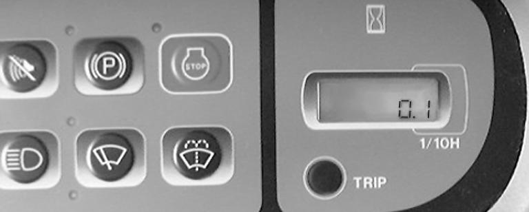
19.HOURMETER -The hourmeter displays the total time that the engine has been operated, in hours and tenths of an hour. It also enables service operations to be scheduled (see the “Servicing Intervals” Section). NOTE: The hourmeter can be read even when the engine is switched off. 20.TRIP METER (specific number of hours) - This control enables the operator to record a specific number of operating hours. Press the control for the hour meter to read zero and for the message “Trip” to be displayed. Then release the control. After approximately one minute the message “Trip” disappears and the normal hour meter reading is restored. To consult the specific number of hours reading, press the control and release it immediately. To cancel the specific number of hour reading, press the control for about 2 seconds and the specific number of hours reading will return to zero. Auto Power-Up Your Link-Belt excavator is equipped with a power up function that will work automatically on demand. During work operations if normal pressure and load settings are “exceeded” a signal is sent to “boost” pressure for a period of 8 seconds. The display monitor will show “Power Up” during boost to inform the operator that normal operating conditions have been “exceeded”.