19 minute read
5-12Upper: Remote Control Valve 1Explanation of Pilot Valve Operation


1 Explanation of Pilot Valve Operation
1. Safety instructions
[1]Note on operation manual
To use this device or equipment safely, throughly read this Operation Manual and understand its contents before starting the device, operating equipment or before starting inspection or maintenance. Always read and follow instructions in the "Safety Precautions" section. Keep the Operation Manual close at hand during operation. Also, keep it in a safe place if the machine is in storage.
[2]Safety precautions
Before using this device or equipment, read and follow the instructions in the "Safety Precautions" sections.
This cautionary information is given to allow operator or service person to use this device or equipment safely and correctly and to prevent injury to the operator or other people and any damage to the device or equipment. Also, the cautionary information is given in either of two categories: "Warnings" and "Cautions" so that the operator or service person can easily identify the degree of danger or damage if the device or equipment is handled incorrectly. Always follow these precautions as they contain important safety information.
Warning
Death or severe injury to the operator may result due to incorrect operation of the device or equipment.
Caution
Injury to the operator or physical damage may result due to incorrect operation of the device or equipment.
Warnings
(1)Make sure that there is no person or obstacle in the working area of the machine equipment before operating the device or equipment. (2)If the machine equipment seems to operate abnormally or in a dangerous manner, immediately shut the hydraulic system down. (3)If abnormal conditions (such as abnormal noise or oil leakages) are found, immediately stop the machine operation and take appropriate corrective actions. Otherwise, personal injury or damage to the machine may result.
Cautions
(1)When you operate the device or equipment for the first time, make sure that the hydraulic circuit and electric wiring are correctly connected, and that connectors and joints are secured. (2)Do not use the device or equipment if its specifications differ from those given on the dimensional outline drawing. (3)Protect the skin from direct contact. It may result in injury. The device or equipment can become hot due to the increased oil temperature during machine operation. (4)Always use the specified grade of hydraulic oils and replace the contaminated oils as recommended. Otherwise, operation failure or damage may result in machine. (5)Be sure to install the filter that has been specified on the dimensional outline drawing, at the inlet of device or equipment.
Cautions
(1)To prevent injury when handling the device or equipment, wear the protective gear if necessary. (2)Carefully operate or service the device or equipment because as the equipment is heavy, incorrect use may result in backache or your fingers being pinched. (3)Do not get onto the device or equipment. Also, do not hit, drop or apply external forces. It may result in operation failure, damage, or oil leakage. (4)If the device, equipment or the floor is contaminated with hydraulic oil, wipe and clean it away. Otherwise, people may slip and hurt themselves or the device or equipment may fall to the floor.
3)Cautions during installation or removal of device/equipment
4)Cautions for maintenance and storage
5)Cautions on performance and functions
Cautions
(1)Before operating or servicing the device or equipment, be sure to turn the power OFF and make sure that the electric motor, engine and other machinery has stopped. Also, make sure that the pressure inside the hydraulic pipe has dropped to zero (0). Release the residual pressure of the accumulator circuit by operating its control lever more than 10 times. (2)Only authorized people should carry out the installation, removal, piping, wiring and other tasks related to the device or equipment. (Authorized people refers to Japanese Class-2 qualified engineers, or technicians who has a basic knowledge of hydraulic system adjustment, or who has completed the Service Training Course of our Department.) (3)Clean the parts mounting holes and surfaces. Otherwise, the bolts may not be secured, or a seal may be damaged, which may result in damage to the device or equipment, or oil leakage. (4)When installing the device or equipment, always use the specified bolts and tighten them to the specified torque, otherwise an operation failure, part damage, or oil leakage may occur.
Cautions
(1)The customer must not modify the device or equipment. (2)Do not disassemble or reassemble the device or equipment without permission. If so, the product may not perform properly and failure or accidents may occur. Only qualified engineers or technicians should disassemble or reassemble the device or equipment if required. As stated in Section 2.5 of this Manual, performance and functions of the device or equipment are warranted only when it has been tested and passed during shipment from our plant. (3)When transporting or storing the device or equipment, be careful to observe the appropriate environment conditions such as ambient temperature and humidity. Also, take measures to prevent rusting and entry of dust. (4)You may need to replace the sealing when using the device or equipment after you have stored it for a long period of time.
Caution
Because this is an important device or equipment for safety, its performance and functions are warranted only when it has been tested and passed during shipment from our plant. The customer must understand this limitation of the warranty when disassembling or re-assembling the device or equipment.
[3]Limitations of Warranty
The device or equipment warranty is limited in the following cases:
(1)External factors such as natural disasters, accidents or other accidental force (2)Misuse or abuse •Use for unintended purposes •Use in unspecified conditions •Inhibited operation •Violation of (operation, maintenance, or inspection sequence) instructions given in the Operation Manual •Skip of (operation, maintenance, or inspection sequence) instructions given in the Operation Manual (3)Unsafe actions (4)Performance and functions of the device or equipment if disassembled or re-assembled by your company or by a third party.
2. Summary
The PV48K2 pilot valve is a remote control valve which has a pressure reducing valve system, and it has four pressure reducing valves in a single valve casing to control the secondary pressure of hydraulic circuit. The output pressure of the hydraulic circuit is controlled by the tilt adjustment of the operation section.
3. Specifications
Primary pressure Up to 6.9 MPa
Secondary pressure 0 - 4.4 MPa (Maximum control pressure) Backpressure tolerance Up to 0.3 MPa Rated flow 20 L/min.
Operating angle ±19° , ±25° (alone) Mass 1.9 kg
Pipes An approximately 3-meter long pipe having the 8-mm internal diameter is appropriate for the best operation response. The returned oil must be fed directly to the hydraulic tank to avoid the influence of backpressure.
4. Structure
The pilot valve has the structure as shown in the assembly section diagram (Page 14). There is a longitudinal axial hole in the casing and the pressure reducing valve is installed in it.
The pressure reducing valve consists of the spool (201), secondary pressure setting spring (241), return spring (221), spring seat (216), and washer 2 (217). The secondary pressure setting spring (241) is set to 0.5 to 1 MPa converted to secondary pressure (depending on the model). The spool (201) is pressed against the pushrod (212) by the return spring (221).
When the operation section such as the handle is tilted and the pushrod (212) is pushed down, the spring seat goes down at the same time, and the hydraulic pressure being set by the secondary pressure setting spring (241) is changed.
The casing (101) has oil inlet port P (for primary pressure oil) and oil outlet port T (to hydraulic tank), and the secondary pressure oil appears at ports 1, 2, 3 and 4.
5. Functions [1]Basic functions
The pilot valve controls the amount of stroke, direction and others of the control valve spool. This control is done by the output pressure of pilot valve that is applied to the end of control valve spool.
In order to satisfy this function, the pilot valve consists of the following elements. (1)Inlet port (P) to which the oil is supplied from the hydraulic pump (2)Multiple outlet ports (1, 2, 3, 4) through which to apply the feed pressure from the inlet port is applied to the end of control valve spool (3)Tank port (T) required for controlling the above-mentioned output pressure (4)Spool that connects outlet ports to inlet or tank ports (5)Mechanical means (including the spring operating on the above-mentioned spool) to control the output pressure
[2]Main part functions
When hydraulic oil is fed to the P port by the hydraulic pump, the spool (201) switches the oil flow from P port to outlet ports (1, 2, 3 and 4) or from outlet ports to the T port. This spool is operated by the secondary pressure setting spring (241) and the hydraulic oil pressure is determined.
In order to change the deflection amount of the secondary pressure setting spring (241), push rod (212) is inserted into the plug (211) so that it can slide.
The return spring (221) operates on the casing (101) and the spring seat (216) so that the pushrod (212) is returned into the zero-displacement direction regardless of the output pressure. It assures spool (201) to return to neutral position. It also has the effect of a counter-force spring for giving an operator an appropriate operation feel.
6. Operation
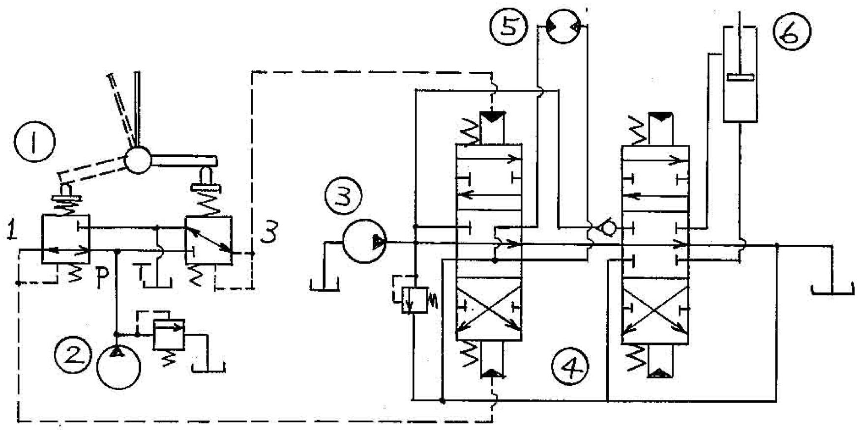
The following explains the pilot valve operation using the hydraulic circuit diagram (Figure 1) and operation diagrams (Figures 2 - 4). Figure 1 gives the typical application example of the pilot valve.
(1) Pilot valve (2) Pilot pump (3) Main pump (4) Control valve (5) Hydraulic motor (6) Hydraulic cylinder
Figure 1. Application example of pilot valve
[1] When the handle is in neutral (See Figure 2.)
The force of secondary pressure setting spring (241) that determines the output pressure of pilot valve is not applied to the spool (201).
Therefore, the spool (201) is pushed up by the return spring (221) (and the spring seat (216)) and outlet port (2, 4) are connected to the T port. Therefore, the output pressure is the same as the tank pressure.
Port

Figure 2. When the handle is in neutral
[2] When the handle is tilted (See Figure 3.)
When the handle is tiled, the pushrod (212) strokes and the spool (201) (and the spring seat (216)) moves downward. The P port is connected to the port (2, 4), and hydraulic oil from the pilot pump is fed to the port (2, 4) and the hydraulic pressure is generated.

[3] When the handle is held (See Figure 4.)
When the handle is tilted and when hydraulic pressure at the port (2, 4) increases to the same level as the force of the spring (241), the hydraulic oil pressure and the spring force are balanced. When the pressure at the port (2, 4) increases above the preset level, both port (2, 4) and P port are closed but T port is opened.
When the pressure at the port (2, 4) drops below the preset level, both port (2, 4) and P port are opened but T port is closed.
Therefore, the secondary hydraulic pressure is held constant.

[4] When the handle is tilted largely (depends on the model)
In some models, if the handle is largely tilted, the pushrod end may touch the spool top end and the output pressure may be kept to the same pressure as the P port.
Also, if the spring seat and the spring have been built into the pushrod and if the handle is tilted largely, the pushrod end may touch the spring. This spring force may change the secondary pressure gradient, and the pushrod end may touch the upper end of spring seat.
As the result, the output pressure may be kept to the same level as the P port.
Port
Figure 3. When the handle is tilted
Port
Figure 4. When the handle is held (Secondary pressure is higher than the preset level)
7. Maintenance Procedure [1]Required tools and tightening torque
Tools Dimensions (mm) Part number Part name Screw size Tightening torque (N•m)
Wrench 22 312 Adjusting nut M14 32 302 Disk M14 68.6±4.9
Special tool (Drawing page 15) 24 301 Joint M14 47.1±2.9
Others •Vapor phase corrosion inhibitor •White kerosene •Anti-seize compound •Sandpapers (#1000 and #2000) •Oilstone •Vice
[2]Maintenance standards
Checkpoints Standard Remarks Leakage amount When handle is in neutral: 1000 cc/min. or more When operating:2000 cc/min. or more If either of them has occurred, replace the entire pilot valve assembly. Conditions Primary pressure: 2.94 MPa Viscosity of oil: 23 mm2/s Spool If abrasion of sliding part is 10µm or more than non-sliding part, replace the entire pilot valve assembly. This large abrasion is almost the same as the large oil leakage as described above.
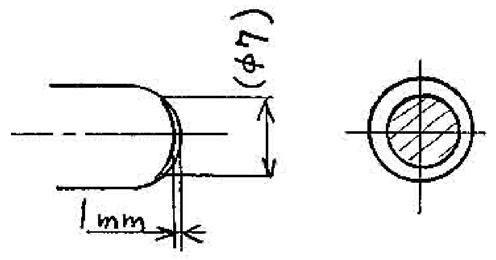
Pushrod If the pushrod end is worn 1 mm or more, replace it.
Looseness of operation section If a 2 mm or larger looseness of the operation section is found due to the worn disk (302) or joint (301), replace it. If the looseness is caused by the unsecured fasteners, retighten and adjust them.
Operation stability If abnormal noise, hunting, dropped primary pressure or other problem has occurred during operation and if it cannot be solved by troubleshooting as described in Chapter 8 "Causes of problems and countermeasures", replace the entire pilot valve assembly.
Note 1)O-rings and other sealing can be reused if not damaged although it is desirable to replace them during disassembly.
[3]Disassembly procedure (1)Preparation (1)Prepare the workbench that has an enough space for parts handling and that is rigid and stable for services. (2)Prepare the required tools and materials listed in Section 7-1.
(2)General notes on operations (1)Because machine parts are very accurate and sensitive, handle them with care. Do not hit or drop them. (2)If parts are secured and if you forcibly remove them (using a hammer or a lever), the metal surface may be burred or damaged. Such damage may lead to oil leakage or decrease performance. Disassemble parts with patience even if you have difficulty. (3)If you leave the disassembled parts on the workbench or if you stop disassembling parts along the way, the parts may rust due to the high humidity or become contaminated by foreign materials. Take appropriate measures to prevent rust and contamination.
(3)Disassembling procedure 1.Wash and clean the pilot valve using the white kerosene. •Cover each port (or opening) using a plug.
2.Hold and fix the pilot valve together with copper plates (or lead plates) on the vice.
3.Remove bellows (501) carefully. •Take care not to damage bellows (501) when removing them.
4.Hold the disk (302) using a wrench, and rotate and loosen adjusting the nut (312) using another wrench. Then, remove the adjusting nut and the disk.
5.Rotate to the left and loosen the joint (301) using the jig.
•Photo 7-5 shows how to use the jig. •CAUTION: If the force of the return spring (221) is strong, plate (151), plug (211) and pushrod (212) may jump out when you loosen the joint (301). Therefore, take care when you loosen the joint.
6.Remove the plate (151).
7.If the force of the return spring (221) is weak, plug (211) may remain in the casing (101) due to the sliding resistance of O-ring. If so, remove the plug using a flathead screwdriver. •When you remove the plug (211), take care not to damage it. Gradually move up the plug by pressing its outer groove using a flathead screwdriver. •When you remove the plug (211), it may jump out due to the return spring (221). Therefore, take care when removing the plug.
8.Remove the pushrod (212), plug (211), pressure reducing valve assembly, and return spring (221) from the casing (101). •Keep a record showing their mounting positions on the casing.
9.When disassembling the pressure reducing valve, push down the spring seat (216) to deform the secondary pressure spring (241), slide the spring seat (216) in a transverse direction, and remove the spool (201) from the larger hole.
Then, separate the spool (201), spring seat (216), secondary pressure setting spring (241), and washer 2 (217) from each other. •Handle the spool (201) taking care not to scratch it. •Do not push down the spring seat (216) more than 6 mm. •Handle these parts as an assembly.
10.If the two-step folding the spring (246) and the spring seat (218) are used, remove them from the pushrod (212).
11.Pull out the pushrod (212) from the plug (211).
12.Remove the O-ring (214) and seal (213) from the plug (211). Use a small flathead screwdriver to remove the seal (213).
13.Cleaning of parts 1)Wash and clean each part using the white kerosene in a washing container. (Rough cleaning) 2)Immerse each part in the white kerosene in the finish washing container, slightly rotate and clean both the inside and outside of each part. (Finish cleaning) Using clean rags, wipe and remove the white kerosene from each part.
•Leave the parts in the white kerosene until dirt and fats have dissolved, and wash and clean them. If you quickly wash the dirty parts, the part surfaces may become scratched. •Always use clean white kerosene. If it is dirty, the parts may be scratched by dirt and the reassembled parts may not have the desired performance. •Do not use compressed air to dry parts because the part surfaces may become scratched or rusted by dust or water contained in the compressed air.
14.Corrosion protection of parts
Coat each part with a corrosion inhibitor.
•If the washed parts are left exposed to air, they will not provide the desired functions when re-assembled.
[4]Assembly procedure (1)Preparation (1)Prepare the workbench and the required tools and materials as with disassembly procedure.
(2)General notes on operations (1)Follow the general notes on operations the same as the disassembly procedure. (2)Before re-assembling the parts, remove metal chips and foreign materials from all parts, and make sure that all parts are free from defects such as burrs and dents. If parts have burrs or dents, remove them using an oilstone. (3)Replace O-rings and backup rings with new ones as a general rule. (4)Take care not to damage O-rings and backup rings when mounting them. (Apply small amount of grease for lubrication.) (5)Apply grease to the parts when mounting them so that they do not fall. (6)Tighten bolts and fasteners with the torque defined in the tightening torque table of Section 7-1. Use a torque wrench to measure the tightening torque. (7)When you have assembled all the parts, cover all ports and openings using plugs to prevent the entry of dust.
(3)Assembling procedure 1.Insert and mount the washer 2 (217), secondary pressure setting spring (241), and spring seat (216) in this order in the spool (201).
Then, push down the spring seat (216) to deform the secondary pressure setting spring (241), slide the spring seat (216) in a transverse direction, and mount the spool (201) through the larger hole.
•Do not push down the spring seat more than 6 mm.
•The parts must be installed in the same position as before disassembly.
3.Mount the O-ring (214) on the plug (221).
4.Mount the seal (213) on the plug (211).
•The lip of the seal (213) must be as shown below.
5.Insert the pushrod (212) into the plug (211).
•Coat the pushrod surface with hydraulic oil.
If the two-step folding spring (246) and spring seat (218) are used, mount them in the pushrod (212).
*1
*3
*1 Seal *2 Plug *3 Pushrod *4 Apply hydraulic oil.

*2
*4
6.Install the plug assembly in the casing (101).
If the force of the return spring (221) is weak, the plug may remain in the casing due to the sliding resistance of the Oring (214).
•Take care not to scratch casing hole (101) when handling the spool (201) using a metal tool.
If the force of the return spring (221) is strong, use the plate (151) and mount four plugs simultaneously, and temporarily fix them using assembly joint (301).
•Take care so that the plug assemblies and the plate (151) do not fly out.
7.Mount the plate (151).
8.Using the jig, mount and secure the joint (301) to the casing (101) to the specified torque.
9.Install the disk (302) in the joint (301).
•Rotate the disk until it evenly contacts with 4 pushrods (212).
If you rotate and mount the disk excessively, a secondary pressure may arise with the lever in the neutral position, and it may cause malfunction. Take care to rotate and mount the disk (302) to the correct depth.
10.Hold the disk (302) using a wrench, and tighten adjusting nut (312) to the specified torque using another wrench.
•Do not change the position of disk (302) when tightening it using a wrench.
11.Apply grease to the rotating part of joint (301) and the top of pushrod (212).
12.Mount the bellows (501).
•Take care not to damage the bellows (501) when mounting them.
13.Spray vapor phase corrosion inhibitor into each port (or opening) and close it using a plug.
8. Causes of problems and countermeasures
It is not easy to locate the failure in the field. The troubleshooting table below lists the possible causes of failure. Because the repair work is difficult, take the "corrective actions" given by referring to the "possible causes" column.
The troubleshooting table lists the typical failure, possible causes, and corrective actions taken. However, machine failure is often caused by a combination of problematic parts rather than a problem with a single part. You should remember that you may need to carry out more corrective actions than those given on the table.
The following troubleshooting table does not cover all possible causes or all countermeasures required.
The repair manager should locate the actual cause of the failure and take appropriate actions when necessary.
Symptom Possible causes Solution Secondary pressure is low. (1)Primary pressure is insufficient. (2)The secondary pressure setting spring (241) is broken or deteriorated. (3)Clearance between the spool (201) and the casing (101) is too large. (4)The handle is excessively loose. (1)Apply the primary pressure. (2)Replace the spring with the new one. (3)Replace the entire pilot valve assembly with the new one. (4)Replace the handle by disassembling and reassembling it.
Secondary pressure is unstable. (1)The sliding parts do not slide smoothly. (2)The pressure of tank line is unstable. (3)Air has entered the hydraulic piping. (1)Repair the sliding parts.
(2)Return the oil directly to the hydraulic tank. (3)Remove the air from the hydraulic line by carrying out deaeration several times.
Secondary pressure is too high. (1)The pressure of hydraulic tank line is high. (2)The sliding parts do not slide smoothly. (1)Return the oil directly to the hydraulic tank. (2)Repair the sliding parts.