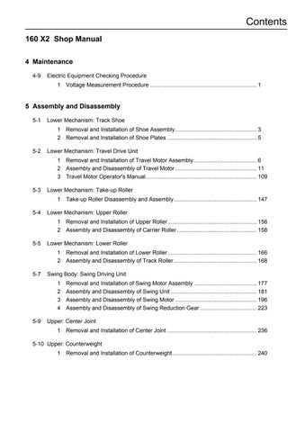
3 minute read
5PTO Assembly and Disassembly Procedures


5 PTO Assembly and Disassembly Procedures
1-1Tools
The table below shows the tools required for the assembly and disassembly of the PTO unit.
Tool name Dimension B Part name
Hexagon bar wrench 10 Hexagon socket head bolt (OSBM1020) Flange socket (PFSBM1020)
Pliers TRR-150 - Locking ring (ORR72)
Torque wrench - Hexagon socket head bolt (OSBM1020) Flange socket (PFSBM1020) Flathead screwdriver - Spring pin (OSPV420) Key - Spring pin (OSPV420)
1-2Disassembly procedure
Read the entire section below on the disassembly procedure, and follow the procedure for disassembling the PTO unit.
The number in parentheses shown after the part name indicates the code used in the assembly crosssection diagram in Figure 2.
The photo shows an aluminum PTO unit. 1. Select a location for disassembly.
Precautions (1)Find a clean location to disassemble the unit. (2)Place a rubber plate or cloth on the work table so as not to damage the parts.
2. Use cleaning oil to remove any dirt or rust from the surface of the pump.
3. Remove the drain port plug (468) to drain oil in the pump casing.
Precautions (1)Remove the plugs from both the front and rear pumps.
4. Remove the flange socket (435) and remove
PTO unit.
5. Loosen hexagon socket head bolts (414), and remove the cover (262).
When a gear pump is mounted, loosen the flange socket (435) and remove the gear pump.
6. Remove the spring pin (885) that fixes the idle shaft (115) using a flathead screwdriver and nippers.
Precautions (1)Be careful not to damage the gear case.
7. Remove the idle shaft (115), and pull out the 2nd gear (117), cylindrical roller bearing (126), and bearing spacer (128).
Precautions (1)Cylindrical roller bearing cannot be removed from 2nd gear.
Precautions (1)Single -row deep groove ball bearing cannot be removed from 3rd gear.
1-3Assembly procedure
The assembly procedure is the reverse of the disassembly procedure. However, follow the precautions below. (1)Be sure to repair any parts damaged during disassembly, and prepare replacement parts in advance. (2)Any foreign matter entering the equipment can create a malfunction. Therefore, after thoroughly cleaning the equipment with cleaning oil, air blow the equipment, and assemble in a clean location. (3)When assembling sliding parts, be sure to coat them with new hydraulic oil. (4)As a rule, replace all O-rings and other seal parts and spring pin with new parts. (5)Use a torque wrench to tighten all installation bolts and plugs to the standard torque specified in the maintenance standards.
1. Select a location for assembly.
Precautions (1)Find a clean location to assemble the parts. (2)Place a rubber plate or cloth on the work table so as not to damage the parts.
4. Install the 2nd gear (117), cylindrical roller bearing (126) and bearing spacer (128), then install the idle shaft (115).
Precautions (1)Attention must be paid to the installation direction of 2nd gear. (2)Be careful for the direction of idle shaft.
5. Install the spring pin (885) to fix the idle shaft (115).
6. Fix the cover (262) with hexagon socket head bolts (414).
When the gear pump is mounted, fix the pump with the flange socket (435).
7. Install PTO unit to the pump main body with the flange socket (435).
2. Maintenance Standards 2-1Standards for replacing worn parts
Replace the parts if pitching is generated to the tooth surface of the 2nd gear (117) and 3rd gear (118) (with 1-pit size being 1 mm and over, and area factor of 5% and over). If, however, the appearance of the part shows significant damage, replace that part. 2-2Tightening torque
Material of gear case Part name Size Tightening torque (N•m) Aluminum Hexagon socket head bolt (material SCM435) flange socket Casting Hexagon socket head bolt (material SCM435) flange socket M10 33
M10 57
Figure 1. PTO unit breakdown diagram
Figure 2. PTO unit assembly sectional drawing