12 minute read
1Explanation of Pump Main Unit Operation


1 Explanation of Pump Main Unit Operation
1. Model Display
O-ring fluorine
ID symbol for model having only difference in control properties
Regulator type: For details, see Instruction Manual for regulator.
Direction of rotation R: Right rotation (as viewed from the side of the axis) L: Left rotation (as viewed from the side of the axis)
Design series number
P: Type mounted with PTO
S: Single pump DT: Tandem-type double pump
Size (Displacement: cm3/rev)
K7V: K7V-series pump
2. Specifications
Size 63 Displacement (cm3/rev) 65.2
Pressure MPa (kgf/cm2)
Rating 35 (357) Maximum 40 (408)
Revolution (min-1)
Maximum*1 2950 Max. self-priming*2 2650 Weight kg (excluding pump No. 4) 72 PTO allowable torque: N•m (kgf-m) 125 (12.7)
Hydraulic oil Type Abrasion-resistant hydraulic oil Temperature range -20 - +95°C
Viscosity range 10 - 1000 cSt (mm2/s)
Recommended filter Return line: 10 µm nominal Suction line: 80 - 150 mesh
*1 Inlet flange portion requires a boost pressure of 0.1 MPa and above. *2 Check inlet flange portion for a pressure of -0.01 MPa and above.
3. Structure and Operating Principles
This pump is constructed to combine 2 units of pumps arranged on the same axis with the 1st gear (116).
At the same time, it is designed to distribute turning force to different gears through the gear system. By transmitting the prime mover rotation to the front drive shaft (111), this pump drives 2 pumps and can simultaneously drive an auxiliary pump provided on a different axis.
This pump comprises mainly of rotary group, the main part of the pump that provides rotation, swash plate group that changes discharge, valve block group that selects oil inlet-discharge and PTO group that transmits performance of the gear pump drive shaft.
Rotary group comprises of drive shafts (111 and 113), the cylinder block (141), piston shoes (151 and 152), the retainer plate (153), the spherical bushing (156), the bearing spacer (127) and the cylinder spring (157). The drive shaft is supported by bearings (123 and 124) at both ends. Shoe is caulked by the piston and forms a ball joint. It has also a pocket section to reduce the thrust generated under the load pressure and balance the pressure to lightly slide over the shoe plate (211). Piston shoe sub-group is pressed to the shoe plate by the cylinder spring via retainer plate and spherical bushing to enable the shoe to smoothly slide on the shoe plate. Also, cylinder block is likewise pressed to valve plates (313 and 314) by the cylinder spring.
Swash plate group comprises of the swash plate (212), shoe plate, swash plate support block (251), tilting bush (214), tilting pin (531) and servo piston (532). Swash plate is supported by the swash plate support block at the cylindrical portion formed on the opposite side of the shoe sliding surface. When hydraulic force controlled by the regulator is guided to the hydraulic chamber provided on both sides of the servo piston, servo piston moves to the left and right. The swash plate then oscillates on the swash plate support block via ball portion of the tilting pin, enabling to change the tilting angle (α).
Valve block group comprises of the valve block (312), valve plate (313 and 314) and valve plate pin (885).
Valve plate with 2 oval-shaped ports is mounted to the valve block, which feeds and collects oil to and from the cylinder block. Oil switched over by the valve plate is passed on to the external piping via the valve block.
PTO group comprises of the 1st gear, 2nd gear (117) and 3rd gear (118). 2nd and 3rd gears are respectively supported by bearings (125 and 126) and valve blocks are installed to the gears.
Now, when the drive shaft is driven by the prime mover (electric motor, engine, etc.), cylinder block simultaneously rotates through the spline coupling. When swash plate is tilted, the piston arranged inside the cylinder block performs reciprocating motion relatively to the cylinder while rotating together with the cylinder block. Therefore, if one piston is taken up for example, while the cylinder block rotates one round, the piston makes a 180° motion in the direction away from the valve plate (oil suction stroke). The piston approaches the valve plate during the following 180° motion (oil discharging stroke). If the tilting angle (α) of swash plate is zero (0), sub-pistons (151 and 152) do not stroke and do not discharge oil.
At the same time, 1st gear produces the rotation of drive shaft, which is transmitted to 3rd gear via 2nd gear to drive the pilot gear pump linked to the 3rd gear.
4. Usage Precautions 4-1Installation
Item Precautions Solution 1)Direction of installation1 As principle, install pump motor with the drive shaft set in horizontal direction. All types
2)Load at shaft end Make sure radial and thrust load are not applied to the shaft end of the pump. If there is possibility for applying above load to the belt gear and equivalents, please consult us and explain your specifications.
3)Removal of anti-rust coat Since anti-rust coat is applied to the shaft end spline, remove the coat with washing before using the spline and apply molybdenum disulfide or other lubricant to it before installing to the coupling. When using washing, be careful not to splash washing to the oil seal portion.
4)Pump coupling and aligning
5)Tightening the pump mounting bolts To couple the pump drive shaft and motor shaft, use flexible coupling as principle. Misalignment between the coupling and drive shaft shall be 0.03 mm maximum.
For mounting the pump, apply a tightening torque for each screw size indicated in Table 1 at the end of this manual. All types
All types
All types
All types
4-2Piping precautions
Item Cautions Solution 1)Direction of rotation and discharge Variable pump has individually different indication depending on the commanding method of regulator. The All types
directions are indicated on the dimensional outline drawing according to respective applications for reference.
2)Sanitation control of piping Provide suction and discharge piping and tank with careful oxidation rinsing and flushing. Particularly, clean the suction piping carefully.
3)Mounting of suction and discharge piping When mounting the piping, do not allow undue force to strain the pump suction and discharge ports. Also avoid tight bending as much as possible. Tighten the mounting bolts with tightening torque provided in the attached Table 1. All types
All types
4)Drain piping (1)Return the pump draining pipe to the pump after placing it at a higher position than the pump as shown in the figure below.
(2)Start laying the drain piping for tandem double pumps with the front pump as much as possible.
It is desirable to provide the drain line with the filter.
5)Drain Pressure Normally set the allowable inner pressure of the main pump casing to 1.0 kgf/cm2 maximum. All types
Tandem Pump All types
All types
4-3On filter
The key point for protecting the pump and other equipment from damage and prolonging their service life depends on whether hydraulic oil is carefully managed. Circuits always require filters of 10µ.
Item Cautions Solution 1)Single rotation circuit With a single rotation circuit, always provide the return circuit from actuator with a filter of 10µ. The following figure shows an example of the filter installation. In addition, provide the suction circuit with a strainer of 80 - 150 meshes. Single tilting Pump All types

Installation example of filter (single tilting circuit)
2)Contamination Relationship between contamination and pump's service life is quite difficult to define, which differs sharply depending on the type and property of foreign substances. Particularly, mixing of dust greatly reduces the life of any type of pump. Under the precondition of no dust, recommended range for contamination should be Rank 9 or below or 2 - 4 mmg/100 cc or below by the millipore contamination index. All types
4-4Hydraulic oil and temperature range
Item Cautions Solution 1)Type of oil Use high-viscosity hydraulic oil of mineral system generally in application with extreme-pressure additives, foam inhibitor, antioxidants, and anti-corrosives. All types
2)Optimal hydraulic oil viscosity and temperature Recommended service viscosity for an open circuit is 10 - 200cSt. For application to a closed circuit or for a motor, hydraulic oil is usable in the viscosity range of 10 - 1000 cSt. It is recommended to use oil in the range of 10 - 200 cSt, however. The temperature range is limited to -20°C - 80°C by the oil seal and O-ring used. Use of the oil at a temperature of 65°C or below is recommended in order to avoid potential deterioration of the hydraulic oil and seals.
When use of hydraulic oil of either ester phosphate, water-glycol or fatty ester types is planned, contact us before using it.
Higher limit of viscosity
Viscosity Viscosity Lower limit of temperature Limit of pump suction
Optimum use Range
Lower limit Higher limit of temperature
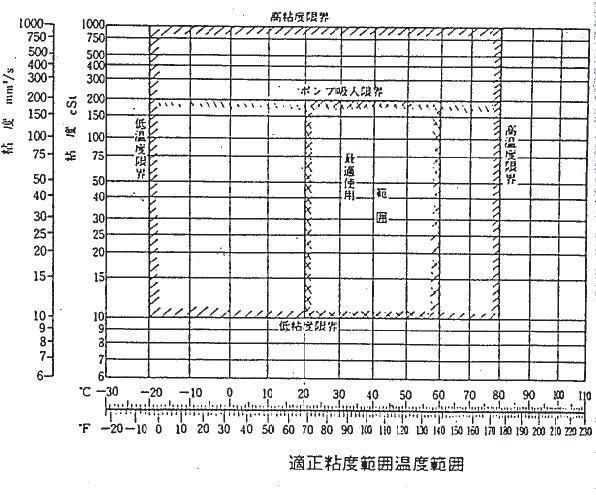
Optimum ranges of viscosity and temperature
4-5Usage precautions
Item Cautions Solution 1)Long-term storage It is not recommended to store pump motor without operation for a long time (1 year or over). Start the motor even for short time during storage. If a unit pump motor is stored, mere turning of the shaft end by hand is effective in retaining the unit in working condition. In the case of a storage for further extended period of time, overhaul and checking will be required. All types
2)Changing the direction of rotation The pump direction of rotation is as indicated in the dimensional outline drawing. If changing direction is needed in the middle, please contact us.
Item Cautions Solution 1)Filling of oil Make sure to constantly fill the pump casing with oil. Highspeed sliding parts such as the bearing, piston, shoe, spherical bushing, and gears are provided in the pump. Problems such as seizing and damage can occur to these parts if the casing is not filled with oil. Always fill the casing with oil. All types
2)Air bleeding Bleed air completely from the circuit and motor. Otherwise, malfunctioning or damage can occur on them.
4-6Filling of oil and air bleeding
4-7Precautions for starting the operation 1) Make sure necessary piping is completed. 2)Check that the suction and discharge directions are correct. 3)Start the motor so that load is not applied to the pump. 4)After starting the motor, let it run at idling speed till the air remaining inside the circuit is completely purged. 5)Check for oil leakage and abnormal vibration. 6)For the pump with a gear box, check the level meter to see the gear oil is fully filled.
5. Cause of Problem and Solution 5-1 General cautions
The following describes the corrective actions required when an abnormality is detected while using an axial piston pump motor.
Following are general cautions: (1)Points to consider before taking actions Before proceeding to troubleshooting, fully understand the property of the abnormality. Judge if the trouble is attributable to a circuitry problem or to regulator, attached valve. Think again if the pump motor is really in trouble. (2)Read the entire section below on the maintenance procedures, and follow the procedure for disassembly. (3)If the motor is to be disassembled even partially, prevent dust from entering the part. (4)Parts are precision-finished. Exercise care when handling them so that they are not damaged.
5-2Procedure for inspecting motor unit problems
Pump is often installed with a regulator, auxiliary valves and pumps, which make it quite difficult to detect the cause of failure. However, if you check the following major inspection items, you may find the abnormal location: (1)Checking of filter and drain oil Check the filter elements. Check if abnormal impurities are detected in large quantity. Minor portion of metal powder consisting of wear powder from the shoes and cylinder is usually found. If excessive quantity of metal powder is found on the filter, the trouble may possibly be attributable to a failure of shoe. Likewise, check the drain oil inside the pump casing. (2)Presence/absence of abnormal vibration and sounds Check the main body of pump for abnormal vibration and sound. Check if they are on regular frequencies such as from the hunting of regulator or relief hunting of attached valve. Abnormal vibration may be attributable to cavitation or internal damage of the pump. (3)When 2 pumps are used When 2 units of a single unit of pump or motor or double pumps are used in the circuit, check the piping of respective pumps. Consequently, it will become clear whether the pump is faulty or a problem is present with the circuit after the pump. (4)Measure pressure of respective components. Do not rush into the overhaul inspection but measure pressure of the respective components first to locate the failed section.
5-3Overloading of motor
Cause Solution Cautions 1)Aren't the speed - pressure higher than planned values? 1)Set as planned.
2)Isn't the torque setting of regulator high? 2)Check the regulator again. 2)Refer to the operation manual of the regulator.
3)Seizure or damage to the internal components of the pump 3)Replace damaged part. 3)Check the filter and drain oil for abnormal wear powder.
4)Regulator piping error 4)Correct the regulator piping.
5-4When excessive drop of pump oil level and/or discharge pressure not rising
5-5Abnormal sounds and vibration
Cause Solution Cautions 1)Faulty regulator 1)Repair the regulator. 1)Refer to the operation manual of the regulator.
2)Seizure or damage to the internal components of the pump 2)Replace damaged part. 2)Check the filter and drain oil.
3)Failure of attached pump 3)Replace damaged part. 3)Remove the attached pump and check the shaft joint section.
4)Failure of attached valve 4)Replace the attached valve. 4)Refer to the attached valve in the operation manual.
5)Regulator pipe error 5)Correct the regulator pipe.
6)Damaged gear 6)Replace the gear.
Cause Solution Cautions 1)Cavitation 1)Prevention of cavitation Check and see if hydraulic oil has turned clouded. 1-1) Boost pressure is low. 1-2) Failure of attached pump 1-3) Inhaling air from the suction pipe. 1-4) Large suction resistance
2)Damage of caulked shoe portion 2)Replace the piston, shoe and/or shoe plate.
3)Cracked cylinder 3)Replace the cylinder.
4)Defective pump mounting 4)Correct the mounting.
5)Hunting of regulator 5)Repair the regulator. 5)Refer to the operation manual of the regulator.
6)Hunting of relief valve of attached valve 6)Replace the attached valve.
7)Damaged gear 7)Replace the gear.
Table 1 Tightening torque list
稾
Part name Size Tightening torque (N•m) Tool name (mm) Hexagon socket head bolt (material SCM435) M5 M6 M8 M10 M12 M14 M16 M18 M20 6.9 12 29 57 98 160 240 330 430 B = 4 5 6 8 10 12 14 14 17 Hexagon bar wrench
PT plug (material S45C) Note) Wrap the seal tape 1.5 - 2 times.
ROH plug material G3/8 or below: S45C G1/2 or above: SCM435[ ] Rc1/16 Rc1/8 Rc1/4 Rc3/8 Rc1/2 G1/4 G3/8 G1/2 G3/4 6.9 10 17 34 49 29 74 98 150 4 5 6 8 10 6 8 10 12 Same as above
Same as above
Figure 1. Pump dimensional outline diagram

Figure 2. Pump assembly cross-section diagram

Figure 3. Pump parts breakdown
Note: (W) (X) (Y) (Z) and (K) (L) (M) (N) in this diagram shows the installation locations of regulator . “See regulator breakdown diagrams (drawing Nos. 21290-1821 and 21290-1822)” Breakdown diagram