12 minute read
Control and operation


Working with the machine
Semi-automatic flap closing
A Joystick
B Joystick with analog stick (if installed)
Push the button S6L left on the down of the right joystick 3 Shovel flap will be closed automatically with full speed.
Push the button S6L again during semi-automatic flap movement. Shovel flap movement will be stopped.
Note!
If you keep the button S6L pushed, the semi-automatic flap closing movement will not start.
If you operate the shovel bucket pedal 7a or 7b during semi-automatic flap closing movement, the automatic movement will be stopped and flap control is switched to manual operation through pedals 7a and 7b
Deactivation of the attachment damping system
The damping system stops the movement of the attachment before the cylinders get suddenly the end position of the piston rods. If necessary, the deactivation of this protection is possible.
Fig. 3-76 Deactivation of attachment damping system
Move the attachment until the damping system stops it. The cylinders are in their end stroke position. Let the two joysticks and pedals in neutral position. Press down the rocker switch S55 on the left joystick 4. The attachment damping system is off.
Caution!
Repetitive movements without the damping system cause fast wear of the components.
Move back the attachment to automatically start the damping system back.
Combined movements
Moving a joystick diagonally results in the work functions concerned being combined. This allows different attachment movements to be activated at the same time.
The operator can do the following movements without any additional manipulations. When the swing movement is actuated, all working functions / movements are possible without affecting the swing movement.
During travel, every attachment movement is possible, but the swing movement has priority. In this case, the travel movement is reduced.
3.4.4Lowering the work attachment when the motor is not running
In an emergency, the attachment can be lowered when the electric motor is not running.
Fig.
Turn the ignition key to contact position 1
Operate the joystick or the foot pedals until the attachment has lowered.
This reserve is limited and is only sufficient for small movements of the pilot control devices.
Only operate the joystick in the directions for lowering the attachment.
3.5General working methods
3.5.1Minimum impact working methods for your machine
To increase the service life of the machine and avoid unnecessary damage and the resulting repairs, please note the following points: stopping the equipment on the walls of the ditch. the equipment is knocked against the material to be removed, in the longitudinal direction too, is not permitted. Repeatedly hitting the work equipment against rock or other hard material will damage steel parts and machine components. and work tool, the work tool could hit or operator. in rocky material. This will extend the work cycles and could result in damage to the bucket and other machine components. l partner if special teeth are required for heavy or special applications. this should occur, slowly lower the machine to the ground. Do not permit the machine to lower quickly and do not intercept the falling movement using the hydraulics, since this could result in damage to the machine.
3.5.2Preparatory activities
Danger!
Risk of fatal injury and damage to the machine when working. erating instructions.
Position the machine so that the load material can be taken up above the idler.
Danger!
Insufficient support and machine damage.
Danger!
Risk of fatal injury due to rotating the machine. Ensure that nobody stands within the hazard area r of the machine.
Caution!
Risk of injury when working.
Always wear safety shoes and, particularly when leaving the cab when demolition work is going on, a protective helmet and safety glasses.
Always wear the seat belt.
Use the horn to give a short warning signal before starting work.
3.5.3Positioning of the machine
Setting up properly is a pre-requisite to safe efficient loading, and helps maintain stability, power and bench levels. It will also reduce operator fatigue. Position the excavator as close to the working face as safety permits.
Caution!
Always ensure there is sufficient clearance between the counterweight and the face, including allowing for any rocks or material that may fall down.
The recommended digging range is about a 90° arc in front of the machine (A).
Note!
Avoid digging at right angles to the tracks.
3.5.4Working with the backhoe bucket
Danger!
Risk of fatal injury and damage to the machine when moving the backhoe bucket.
Ensure that the backhoe bucket is not slewed too close to the cab. tor.
Ensure that nobody is standing within the hazard area of the backhoe bucket.
Align the shovel arm in such a way that its underside is at an angle of approx. 30° forward to the vertical.
Align the backhoe bucket in such a way that its underside can enter the ground at an angle with the axle of the shovel arm between 10° and 20°.
To lift out the grab material, slowly and evenly slew in the shovel arm.
As soon as the shovel arm is at an angle of approx. 45° backward to the vertical, raise the boom slowly and evenly in addition to slewing in the shovel arm and the backhoe bucket. Stopping suddenly will result in impact loads and vibrations. When the backhoe bucket is full or the shovel arm can no longer be slewed in, raise the boom and backhoe bucket until the filled surface is parallel to the ground.
Note!
For a efficient digging, the depth of the of the shovel arm.
Loading the transport vehicle
Danger!
Risk of fatal injury due to falling grab material.
Do not load the transport vehicle so high that the grab material could drop out over the walls of the vehicle.
Ensure that nobody is standing in the danger.
Load an occupied truck only if all safety requirements are fulfilled, notably in order to protect the truck operator.
3-85 Emptying grab material
If possible, the machine should stand higher than the transport vehicle to avoid having to lift the grab material unnecessarily.
Stop the transport vehicle in a position that allows it to be loaded from the rear or the side.
Slew the machine's equipment above the loading area of the transport vehicle. Distribute the grab material evenly over the loading area of the transport vehicle by slewing the backhoe bucket and shovel arm out, slewing the upper carriage and possibly also moving the boom.
If the backhoe bucket is not sufficiently emptied or there is still grab material in the backhoe bucket, slew the backhoe bucket in and out several times to loosen the grab material.
3.5.5Working with the Shovel bucket
Digging
To maximise machine power and breakout, maintain grade and fill the bucket, correct digging angles and technique should be used.
Most digging should be started with the bucket almost fully crowded back (50mm off stops or end of cylinders).
When cleaning up or digging at floor level, angle the teeth aggressively to break out any toe that may be encountered.
Keeping the heel of the bucket off the ground therefore creating a void under the rear of the bucket.
Operate with the teeth and bucket lip doing all the work.
Note!
Avoid digging at right angles to the tracks.
Caution!
Each time the stick is crowded back to commence a cut, extreme caution must be taken not to hit the tracks.
The clam must always be closed when di Avoid working on the cylinder limits and bucket stops during the digging cycle. Continual use of these practises will lead to premature failure of seals and Orings and can cause stress fractures to the clam, stick and bucket and damage to the boom and superstructure.
Crowd the bucket in (down) while closing the clam. This practise makes use of gravity to help minimise shock loading on the bucket cylinders.
Never dig, or attempt to bring down any material overhang, with the bucket while the clam is open or partly open.
Do not attempt to dig or clean the floor or face with the clam open. These practises can cause considerable damage to the clam cylinders.
Unload the bucket
Fig. 3-87 Unloading of the bucket
When dumping the load, tip the bucket forward slightly as the clam opens. This helps direct the material to fall centrally into the tray and avoids spillage.
The position of the bucket backboard when the clam opens, directly affects the position of the load in the tray.
Bucket in ideal position resulting in material falling straight down. Loading centre of the haul truck.
Attaching and removing attachment parts safely
have general approval from Liebherr for installation or attachment may not be insary for this purpose.
chine on level, firm ground.
not safely positioned on the ground or supported with appropriate supports.
s, you must store the equipment, switch off the engine and press the start key to the contact position and both joysticks draulic system.
and which have sufficient load carrying capacity.
es not have sufficient load carrying capacity. Wear work gloves when working with wire cables.
tilted up. Never use your fingers to locate bores; use the correct punch for the procedure.
all bolts and connections are tight.
the hydraulic circuit to stop dirt entering. Only allow authorized persons in the vi- cinity of the machine or the lifting device used.
Removing and installing attachment pins safely hole conductor held by another person must be used. the bolt's threaded hole and only hammer these screws. means of castle nuts and cotter pins, first drive the bolt to the stop, then screw the castle nut by hand until contact and then only pull it far enough to push in the cotter pin.
3.6Transport
3.6.1Travelling procedures for mining machine
The life expectancy of undercarriage components is based on standard working conditions with a maximum travel ratio of 5% per service meter unit. Working and / or travelling on uneven ground and / or abrasive material will influence the lifetime of the components and attract additional cost for the undercarriage components.
Downhill or uphill travel on a slope has also an effect on the life expectancy of undercarriage components and on their wear rate. Indeed, even if the slope angle is below the maximum permitted travelling angle, the increase of the slope angle causes the increase of the force and of the contact pressures applied on all track components (track pad assembly, sprocket, ...). On an indicative basis, the travel force applied on the track components is multiplied by two from a slope angle of 5° (8,7%) and is multiplied by 2,5 from a slope angle of 10° (17,6%).
In general travel action has to be kept to the lowest level that is possible. Minimize travelling with turning through a narrow turning circle and long distance travel.
To minimize the travel ratio, professional mine planning with longfront winning sections is preferred. If digging operations at various spots are necessary, a proper short term and long term plan of winning operations has to be employed to guarantee long term use of the excavator at one place before moving to another location.
However, if frequent machine movement is necessary, the following set of procedures defined by Liebherr to minimize possible machine damage, downtime and wear have to be taken into consideration.
General
In order to move the machine forwards: with the excavator in standard forward position, depress travel pedals all the way forward with the toes. Direction of travel is in the direction of idlers.
In order to move the machine backwards: with the excavator in standard forward position, depress travel pedals all the way down with the heels. Direction of travel is in direction of the drive sprockets.
Moving the machine during loading operations
Moving the machine during loading operations means adjustment of excavator dig- ging and / or truck loading position of some meters.
Important procedures: cket and close up the attachment to a position as close as possible to the excavator undercarriage. on the ground and lifting the machine, then counter turning the undercarriage, is not allowed, because it could cause premature structural damage to the machine. terial around the tracks where the machine will not turn, you must move the machine several meters forwards and / or backwards and attempt to turn again. ator can use the swing function to assist in turning the tracks, i.e. if turning to the right, swing upper deck to the left and vice versa.
Walking the machine over distance
Fig. 3-88 Hazard area r
Walking the machine distances means any movement of the machine of more than 100 m or for a time period longer than 3 minutes, whatever comes first.
In addition to above mentioned guidelines, when moving the machine during loading operations, the following procedures apply: clean all very dirty parts of the undercarriage and remove the unwanted materials.
with a heat gun, to monitor the temperature of the drive components, including the track and carrier rollers.
Danger!
During the movement of the machine, the person which is checking the temperature of the different rollers must always be out of the hazard area r of the machine and t and in radio contact with him.
For the checking of the temperature, the excavator should stop moving. And only when the excavator is stopped, the person could go in the hazard area r to check the temperature of the different rollers.
The machine could only start moving again when the driver has seen the operator out of the hazard area r growing up about 20°C above ambient temperature, interrupt travel and only commence again after parts have sufficiently cooled. to speed up cooling procedure it is ad- visable to have a water truck standby, to hose the heating components during travelling or cooling break. vene with mine safety regulations, swing whilst travelling to equally load track rollers. However, always ensure that clear forward vision is maintained.
Travelling the machine down grades or upgrades
In addition to above mentioned guidelines, when moving the machine during loading operations or when walking the machine distances, the following procedures apply: the machine down with the track motor first, i.e. the machine is moved backwards. the final drives must be at the rear of the excavator. indicated in the "Technical data" section of this manual (machine must be able to walk up unaided). When moving down the ramp never allow the machine to fall down on the attachment. When walking up the ramp never use attachment to assist the movement by pushing with the hydraulic power of the bucket, stick or boom.
Travelling the machine first time
The slide bearing (friction bearing) of the track rollers needs some time for runningin. If the bearing becomes hot at an early stage of machine life, this may cause lubrication problems during further life. Therefore when travelling the machine the first time aside from all above mentioned guidelines it is strongly recommended to move carefully and at reduced speed.
Note!
Warranty may become void if failure to recognize and comply with the recommended travel operating procedures, as outlined in this document, is noted.
3.6.2Excavator lifting and lashing operations
Danger!
For safety reasons, always consider th e precautions given in this section.
Lifting precautions
Lift element: sponding transport drawing, of other kind (cables, chains, slings) if necessary, es in accordance with the regulations, e corresponding transport drawing, always respecting the angles given on the sticker for lifting and lashing operations (refer to the description below).
Additional lifting precautions for backhoe buckets
When you lift the backhoe bucket, also obey the precautions that follow: he center of gravity of the bucket. tions. The height B1 gives the correct transport position as shown in the transport drawing.
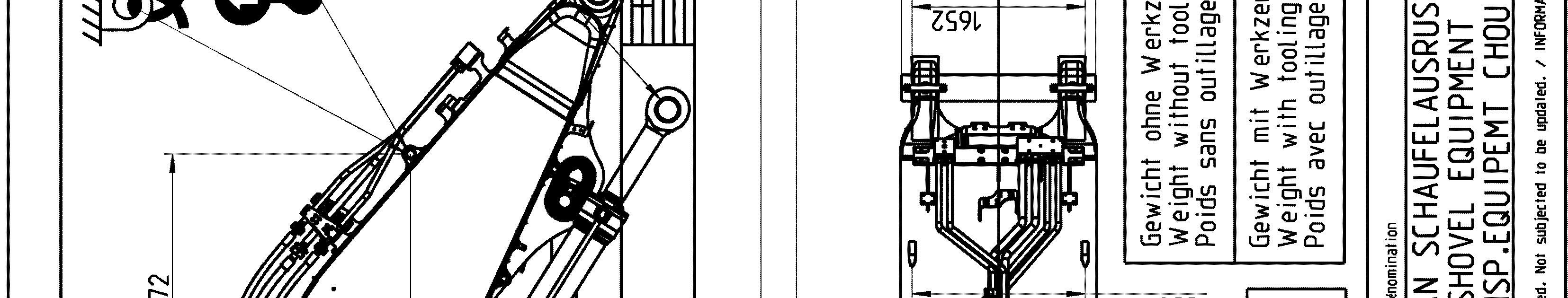
Additional lifting precautions for shovel buckets
When you lift the shovel bucket, also obey the precautions that follow:
Lashing precautions
Lash element: in order to ensure safe lashing, he center of gravity of the bucket. g configuration indicated on the corresponding transport drawing, e corresponding transport drawing, always respecting the angles given on the sticker for lifting and lashing operations (refer to the description below), supporting surface so as to avoid element to slip (e.g. using wooden parts, nonslip mats...), friction is guaranteed by manufacturer certificates, between each contact surface (e.g. between the load and the support, between the support and the flatbed trailer), act surfaces between the flatbed trailer and the load carried are free of dirt, ice, snow, oil and grease.
Additional lashing precautions for backhoe buckets
When you lash the backhoe bucket, also obey the precautions that follow: he center of gravity of the bucket. tions. The height B1 gives the correct transport position as shown in the transport drawing.
Additional lashing precautions for shovel buckets
When you lash the shovel bucket, also obey the precautions that follow: the stickers placed on the bucket.
e center of gravity of the bucket.
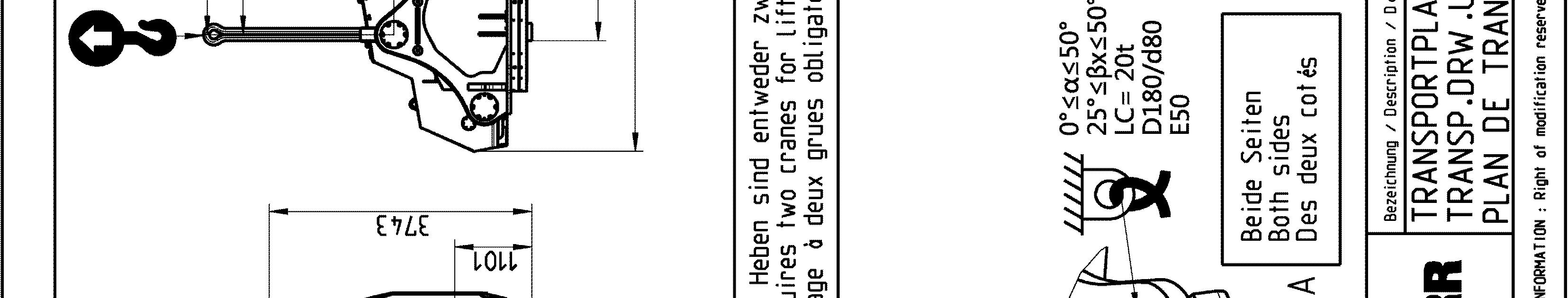
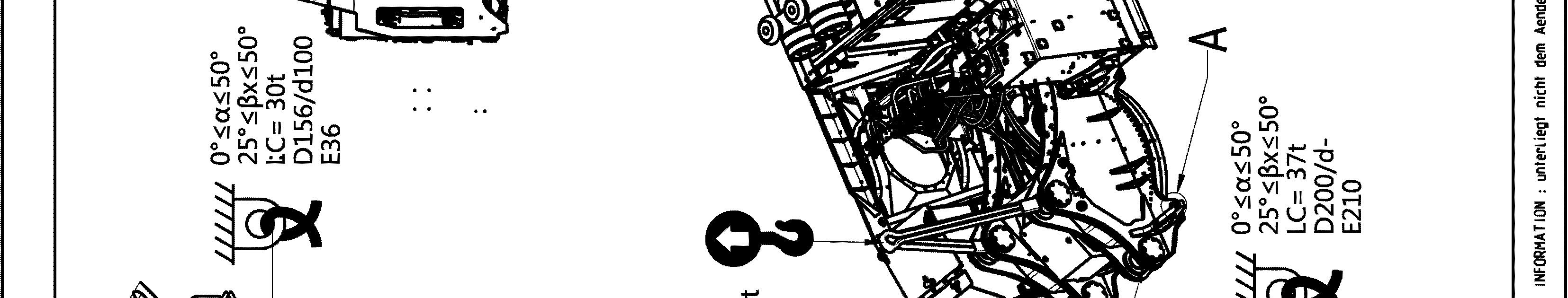
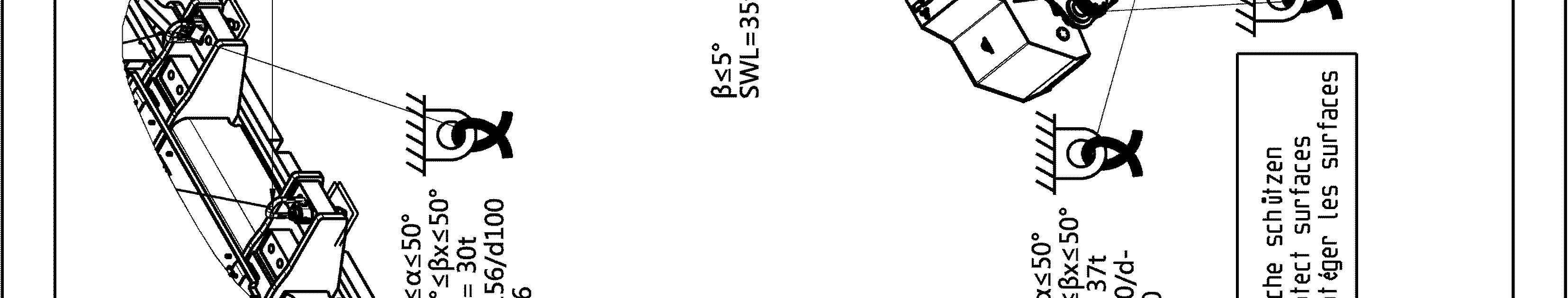
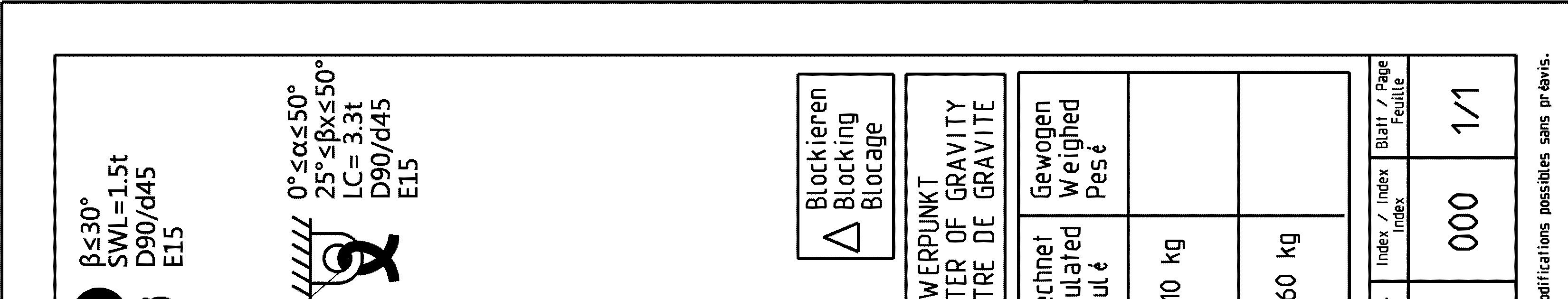
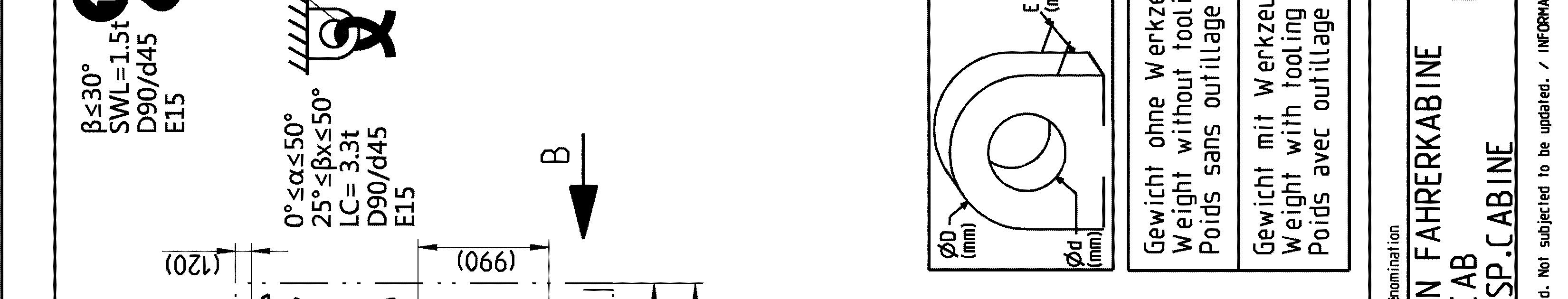
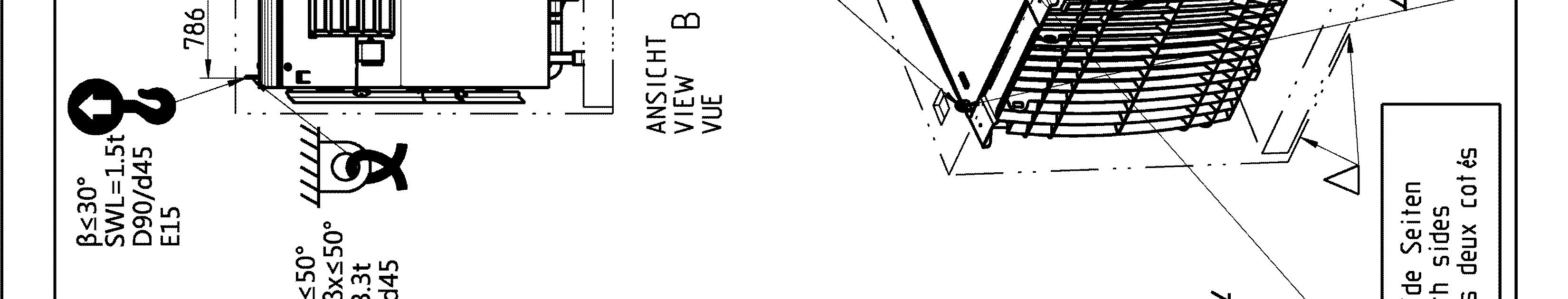
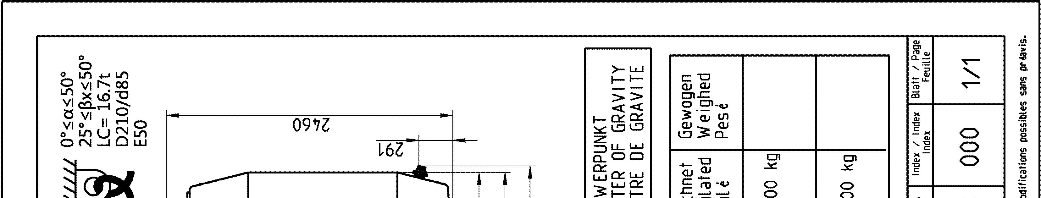
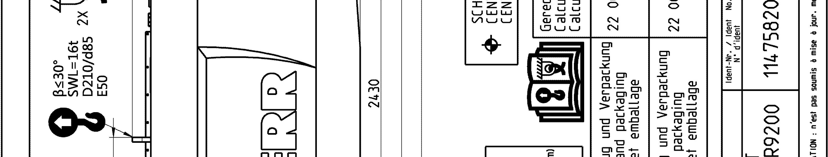
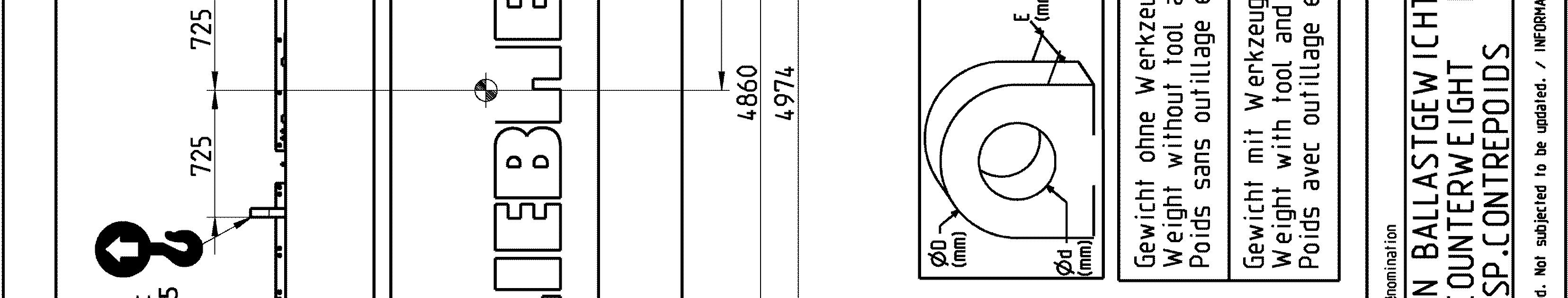
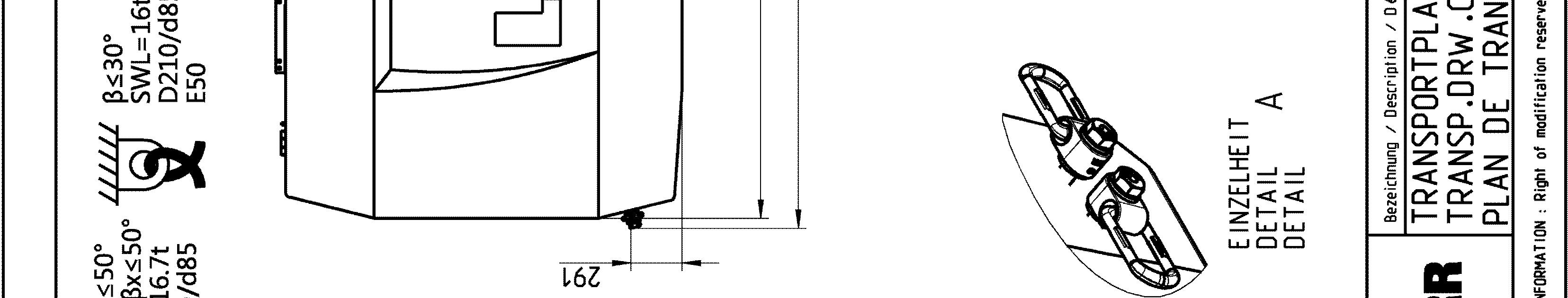
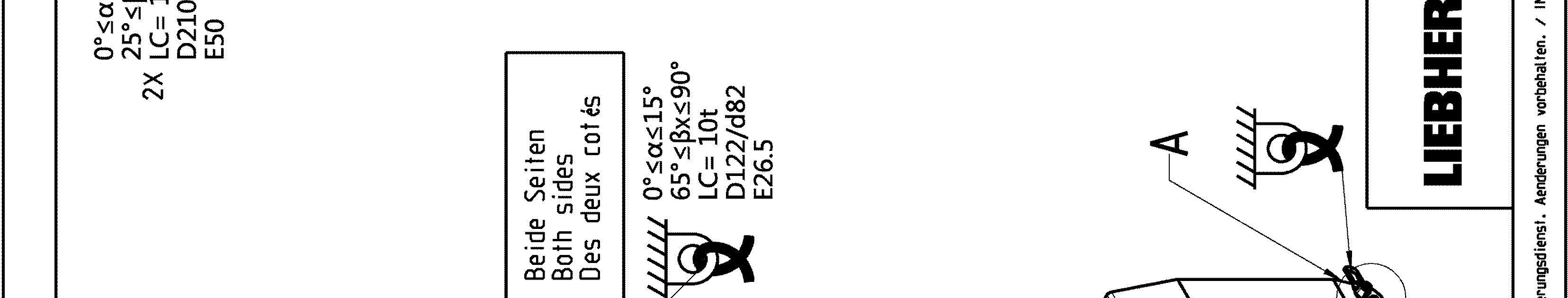
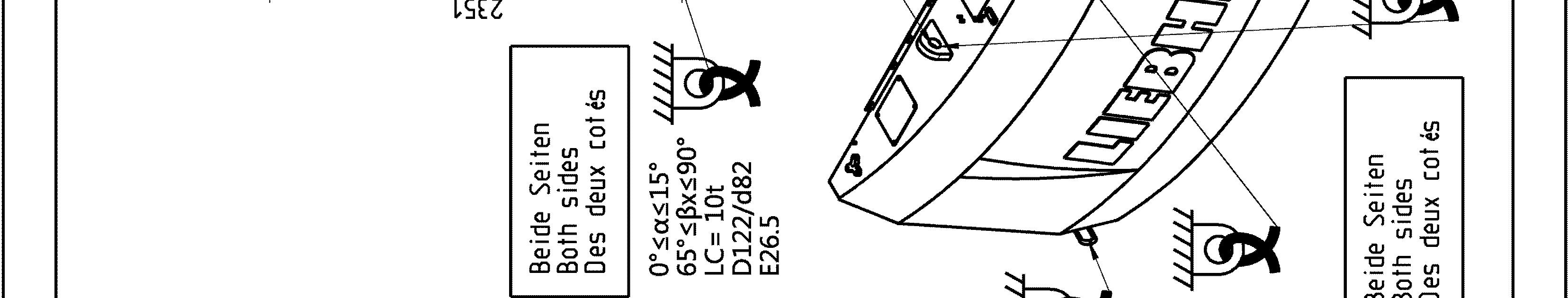
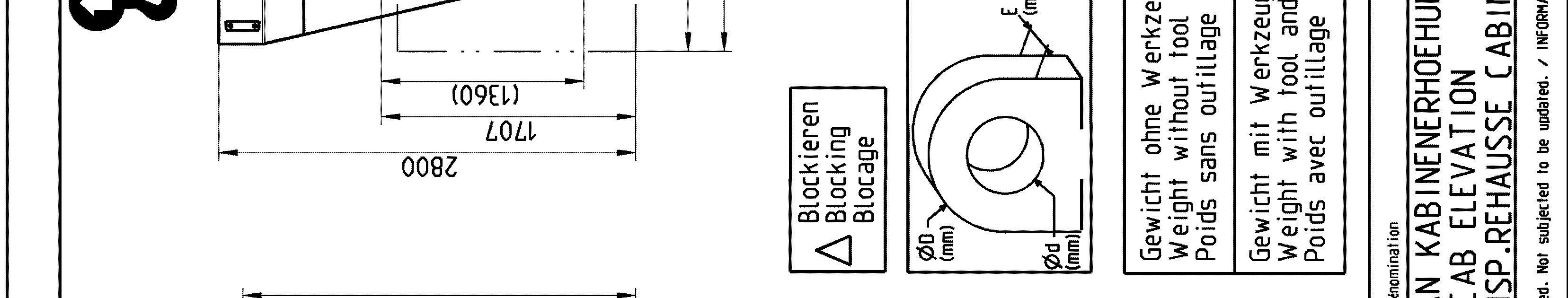
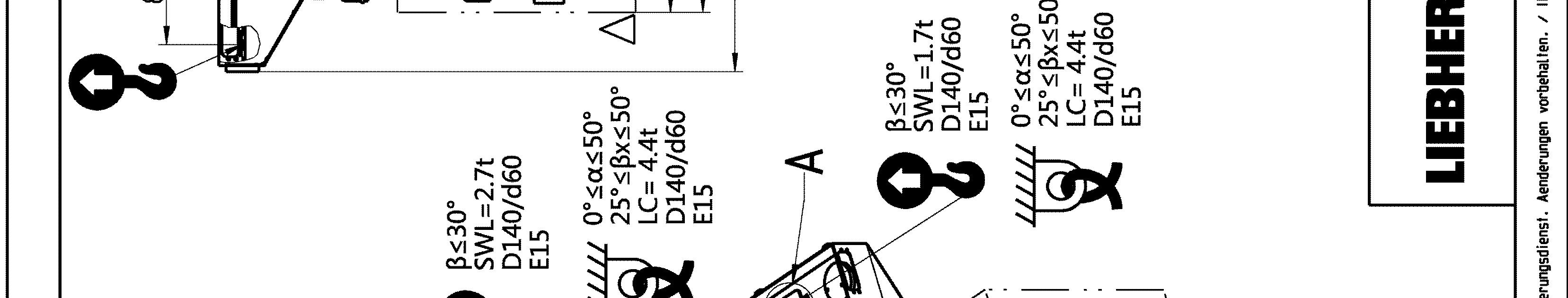
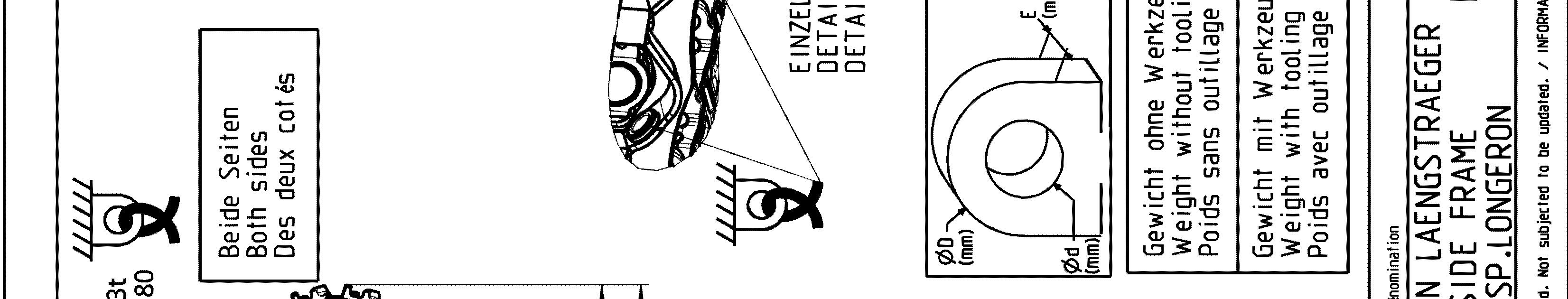
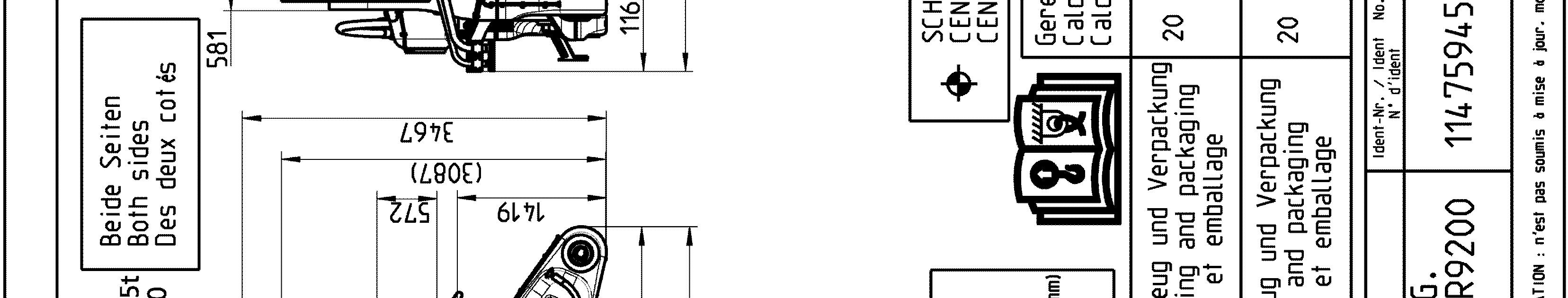
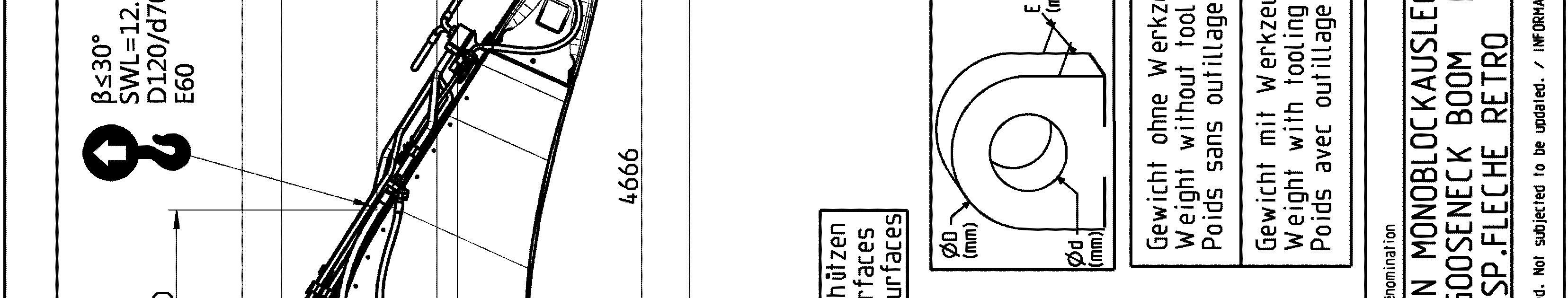
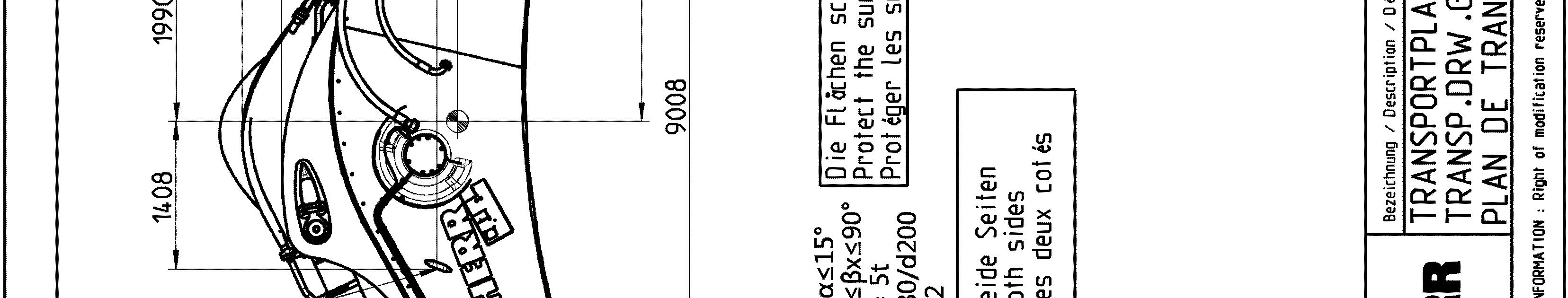
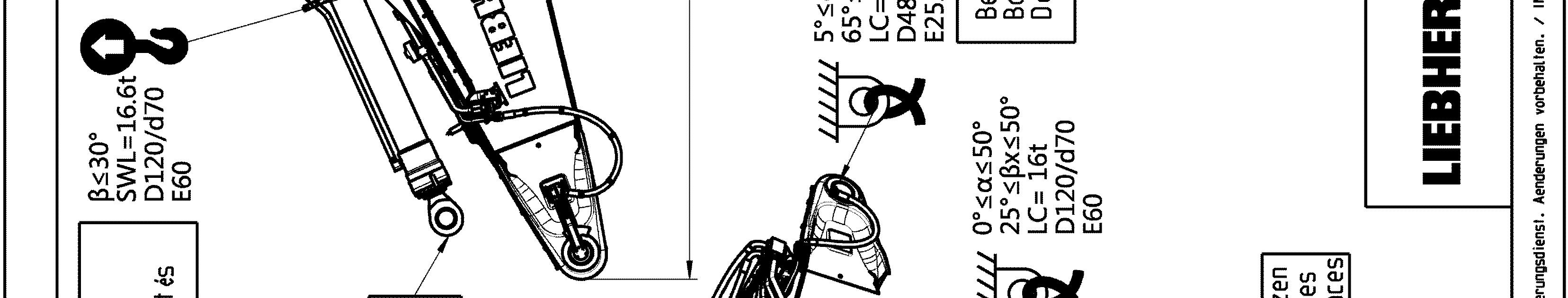
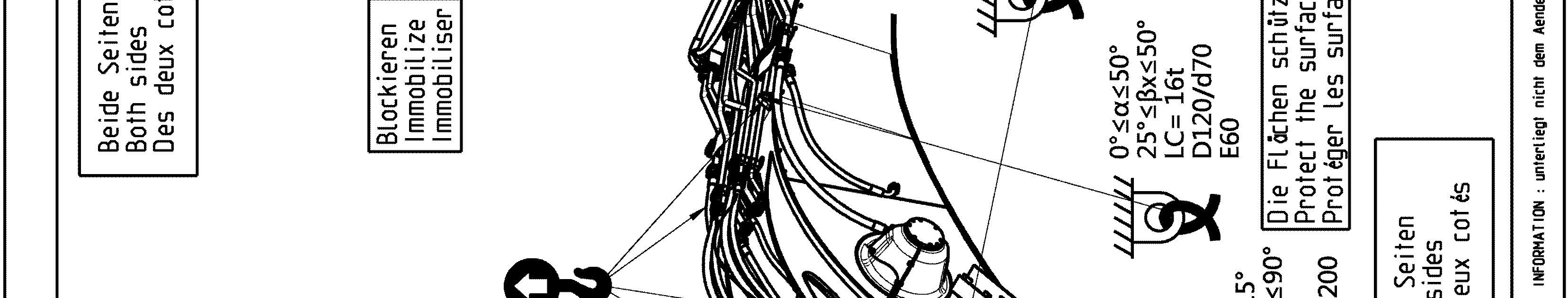
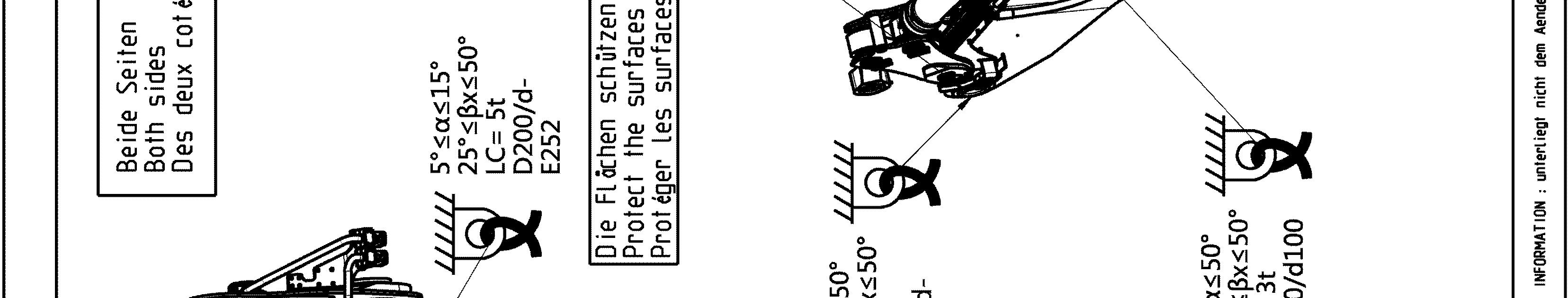
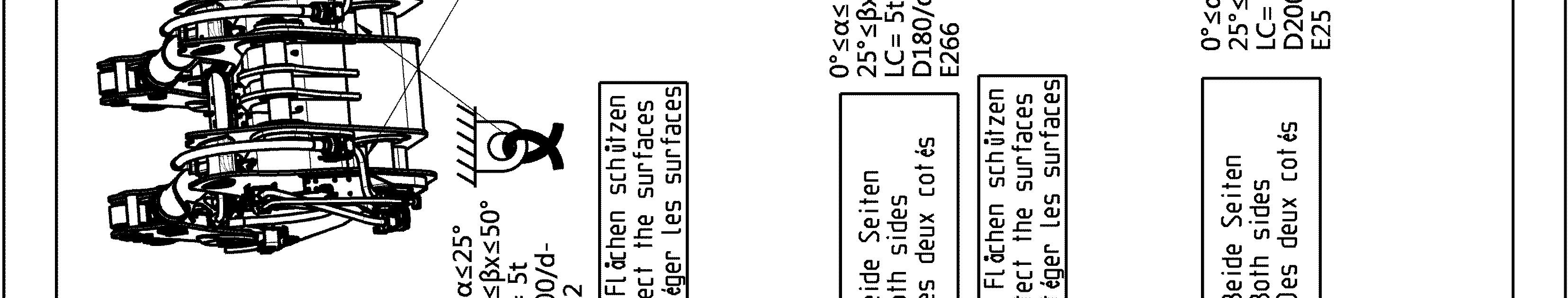
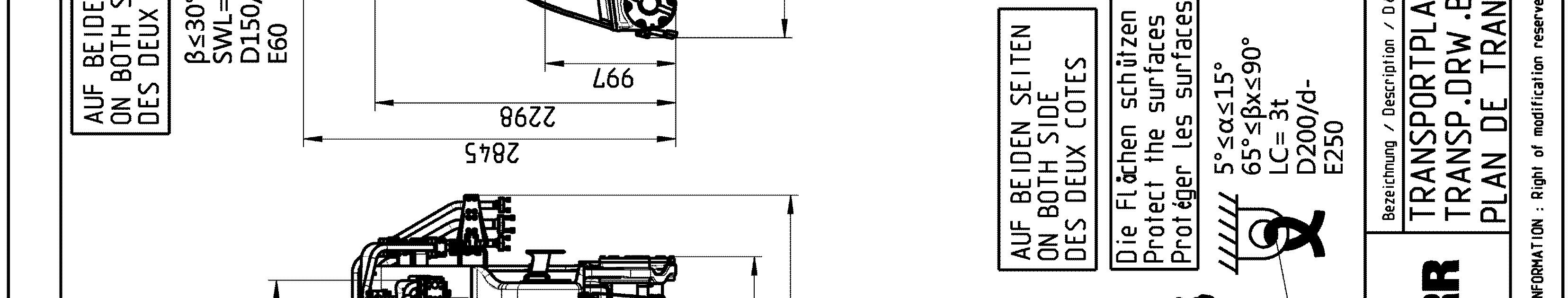
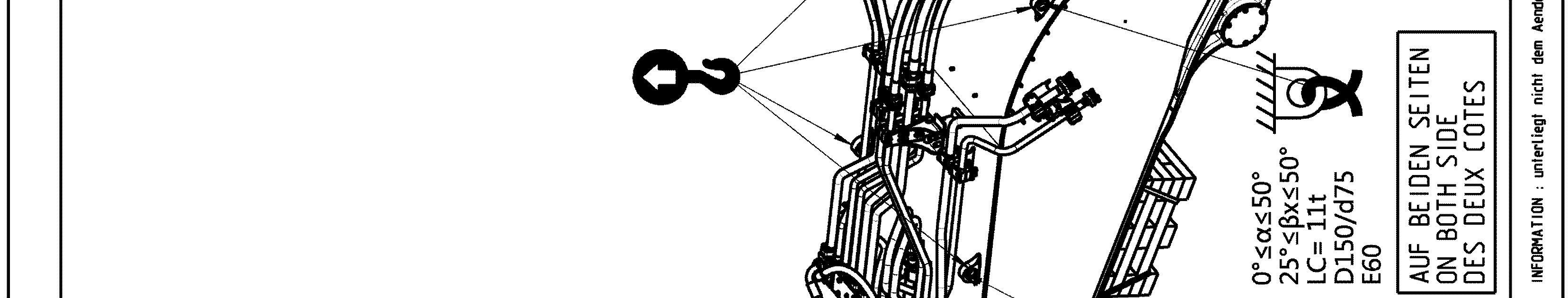
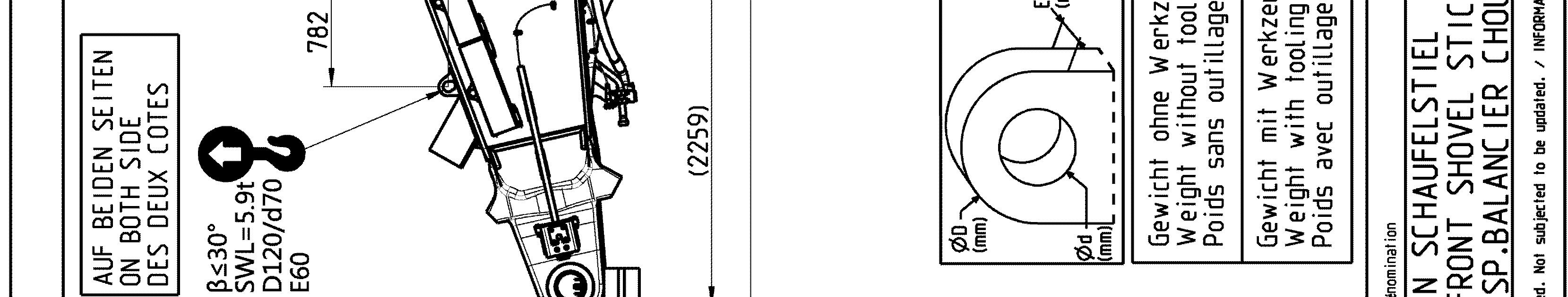
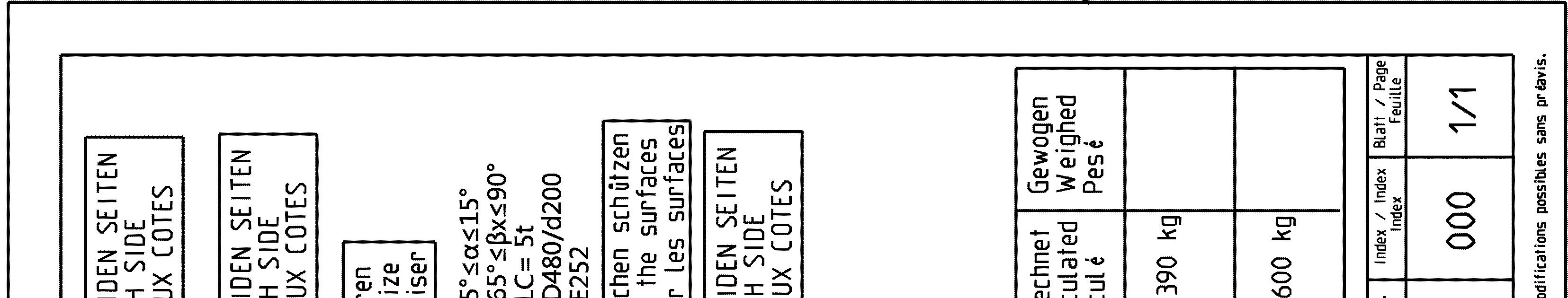
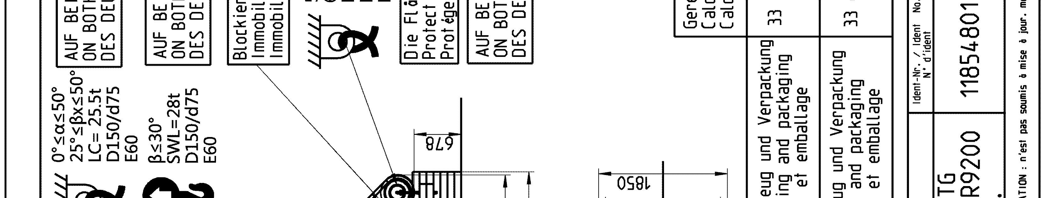
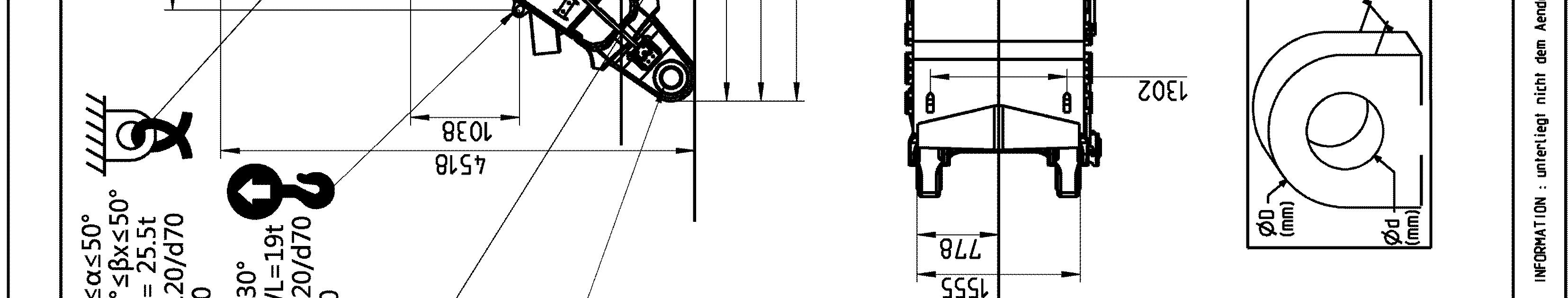
Sticker for lifting and lashing operations
The following sticker is placed next to each transport drawing on the related part and package. It shows rules and precautions which you must obey for transport operations.
And Lashing Operations
The Lashing Capacity LC is the maximum force that the lashing ring can hold in accordance with the angles given on the transport drawing.
The Safe Working Load SWL is the maximum load that the lifting ring can hold in accordance with the angles given on the transport drawing.
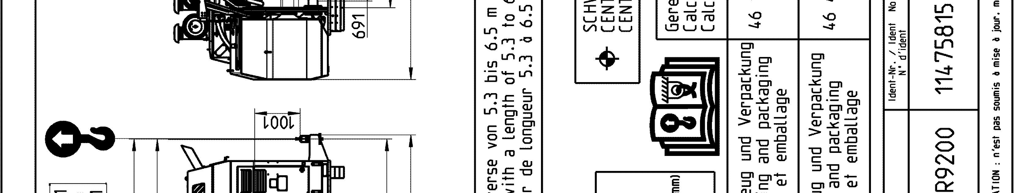
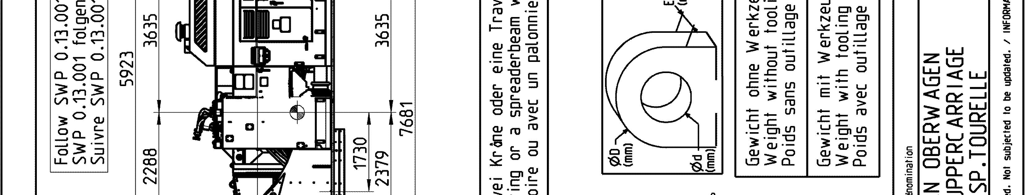
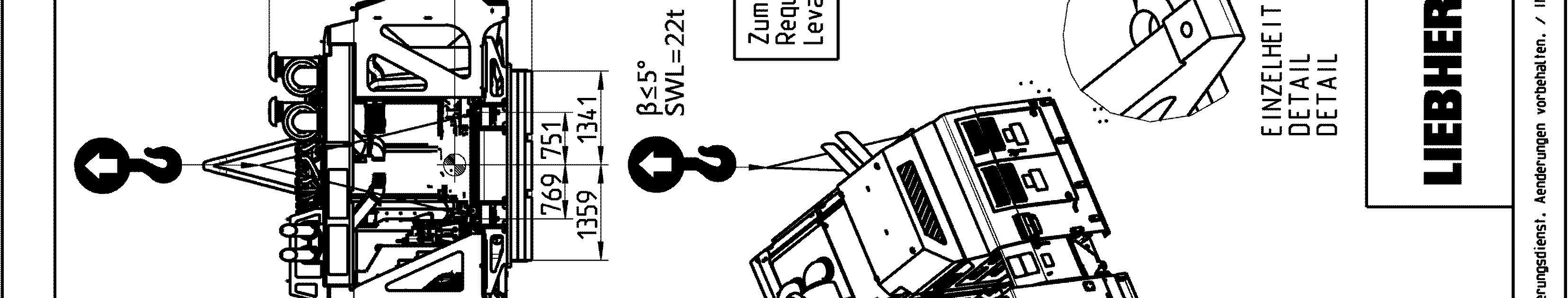
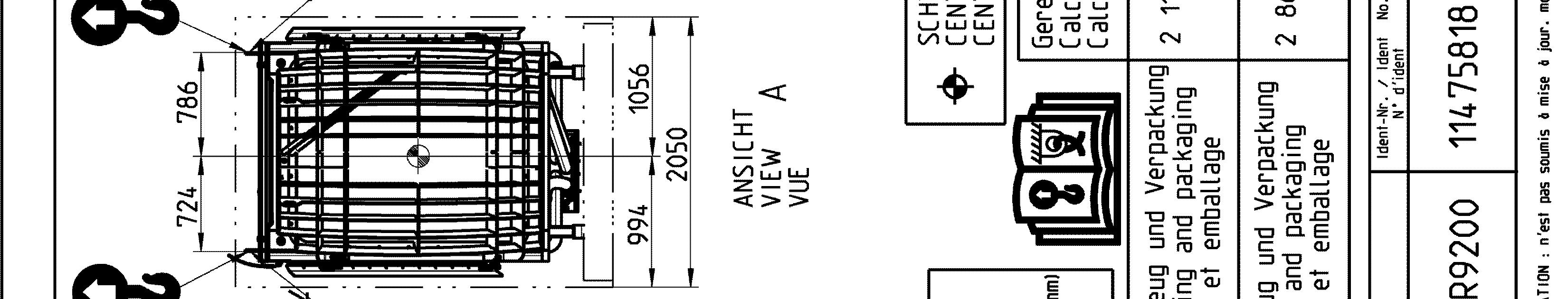
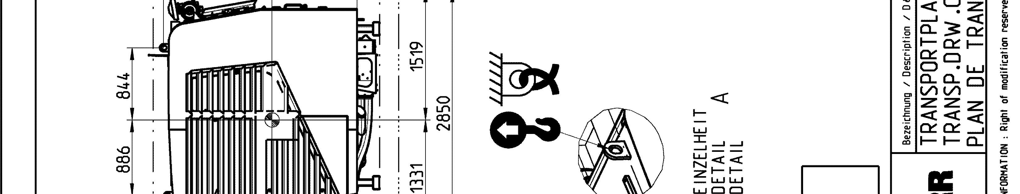
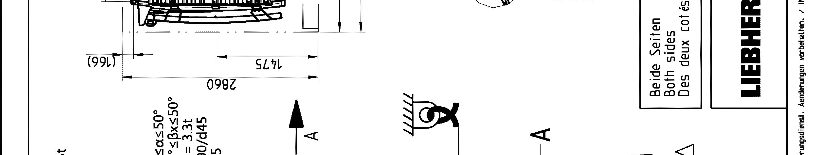
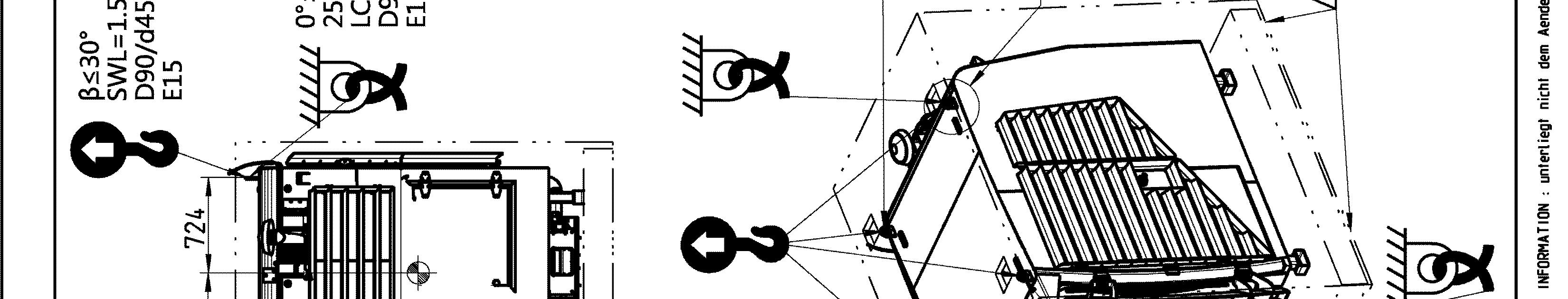
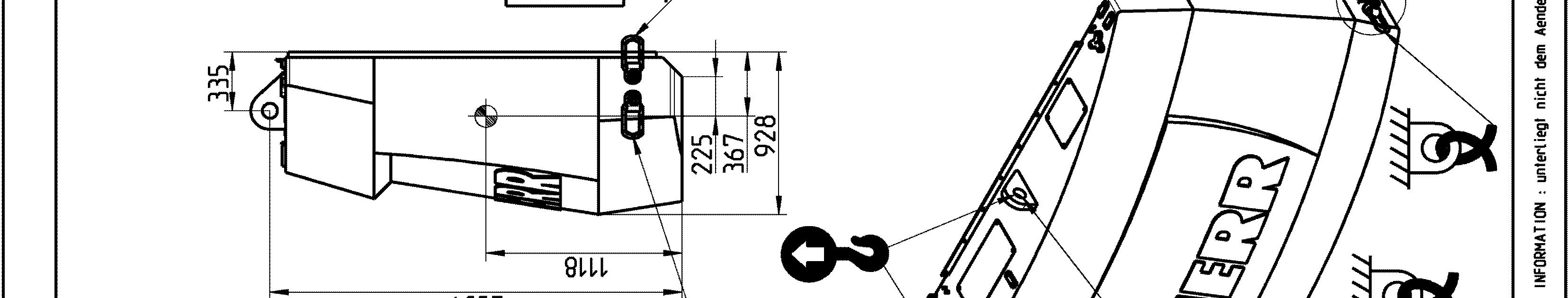
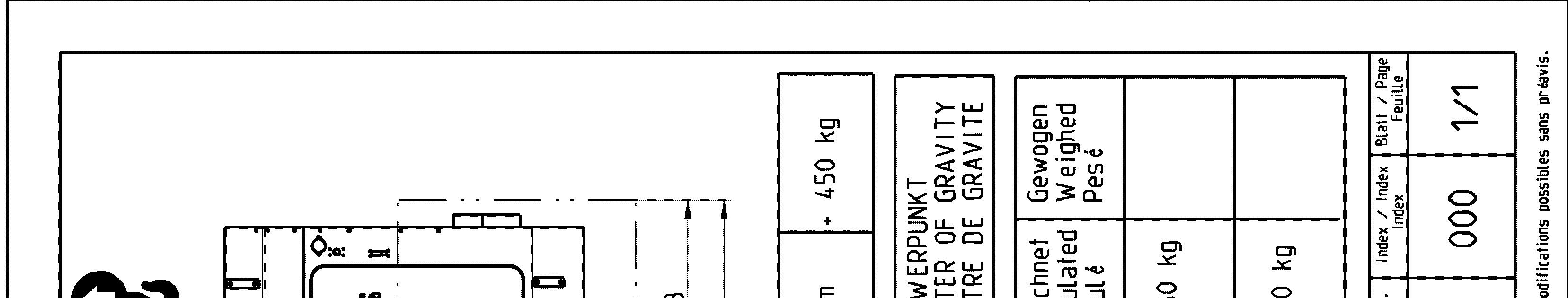
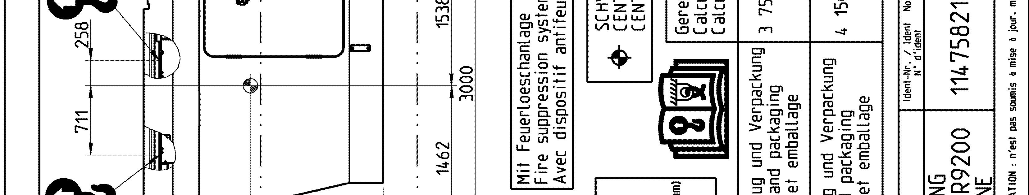
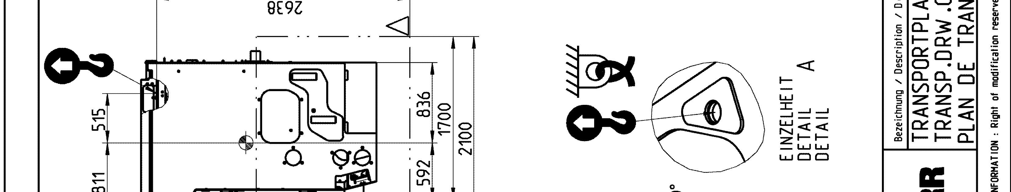
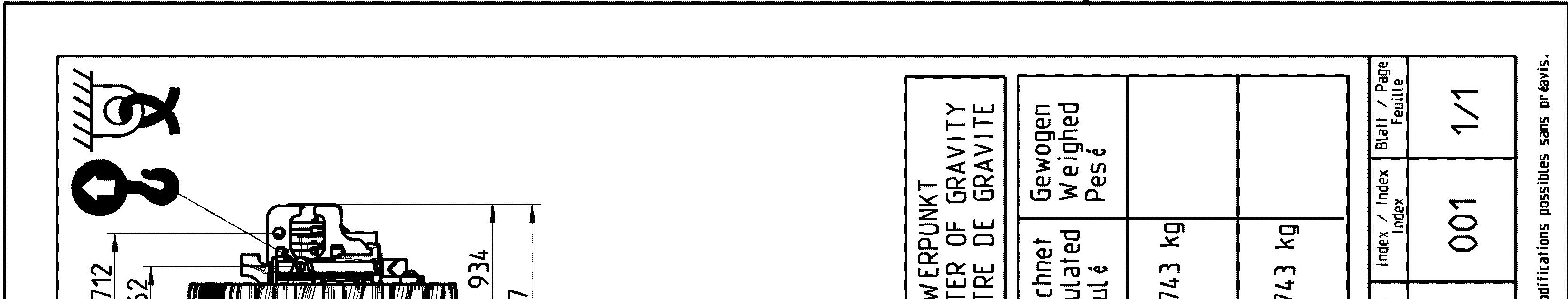
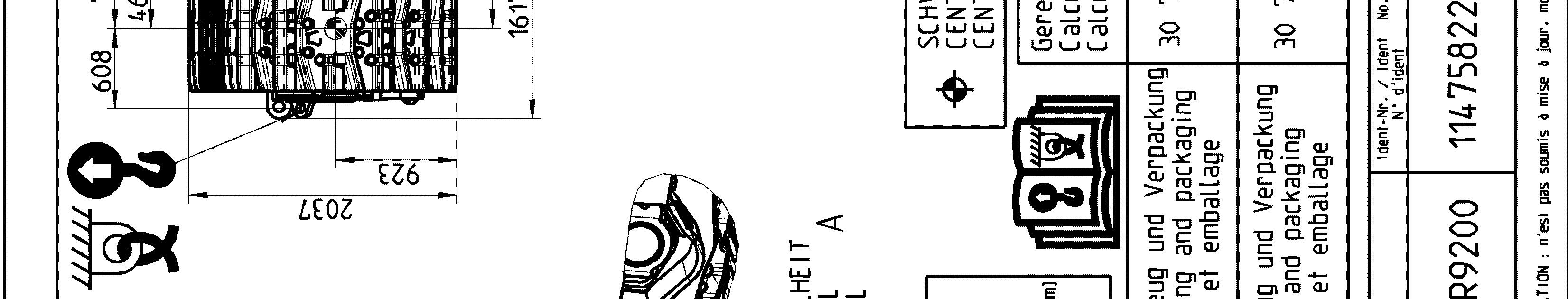
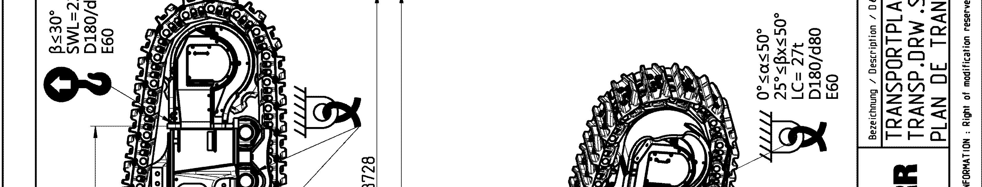
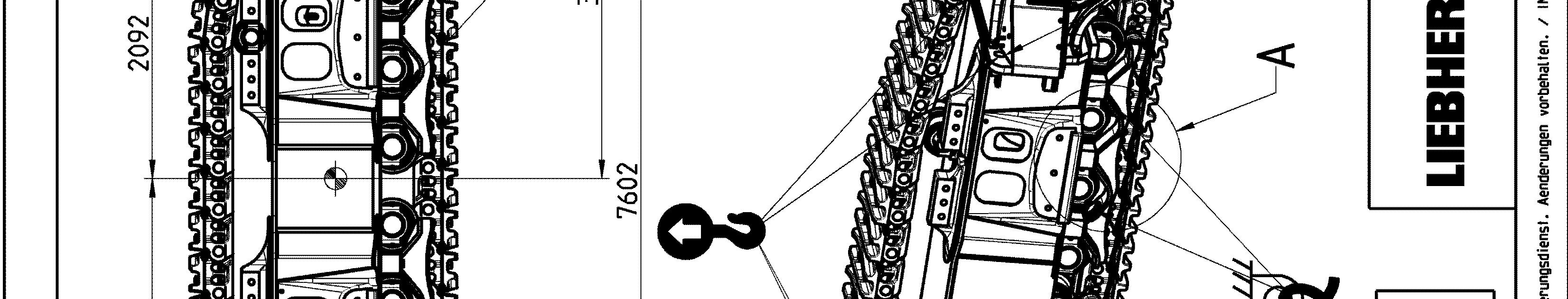
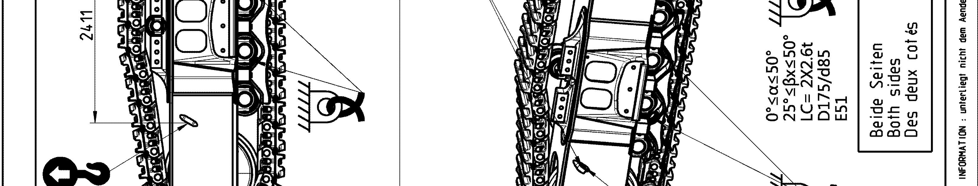
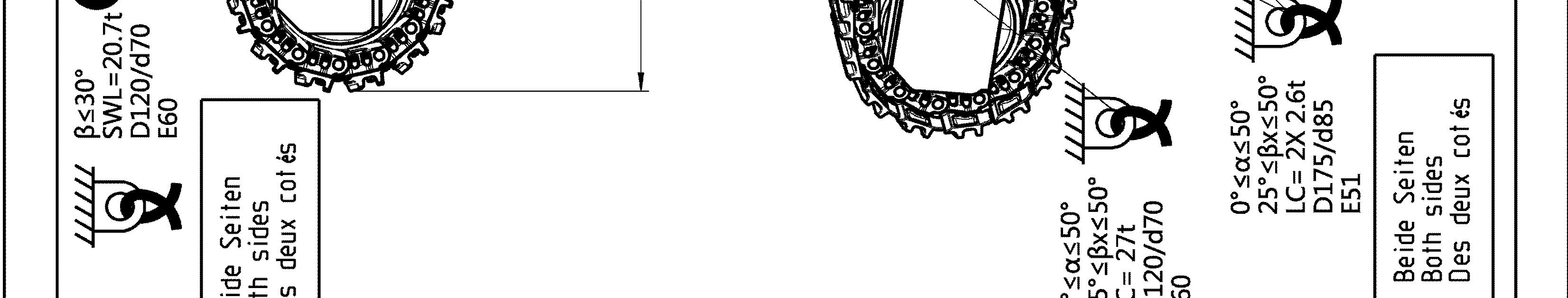
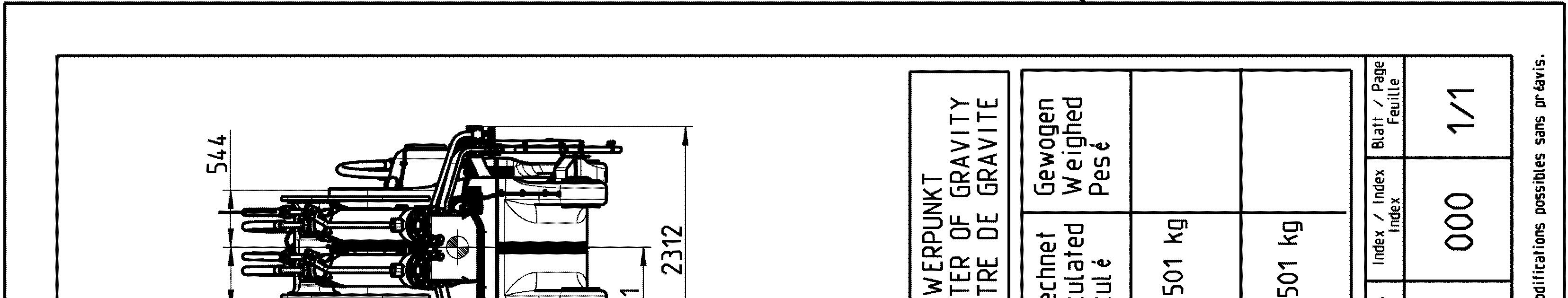
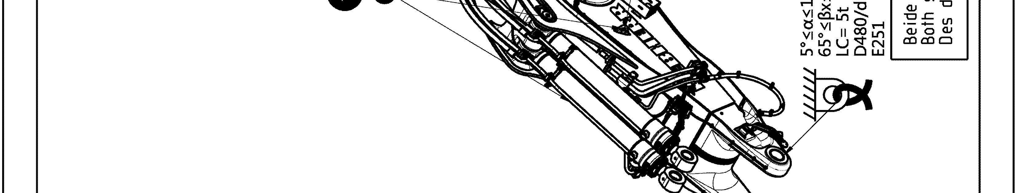
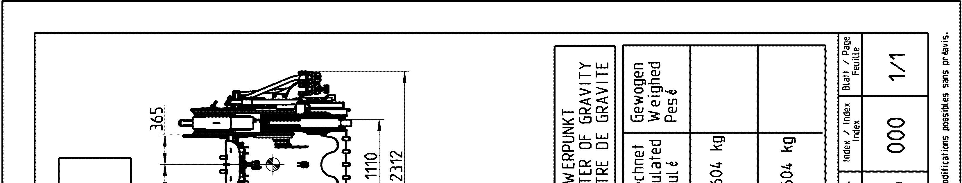
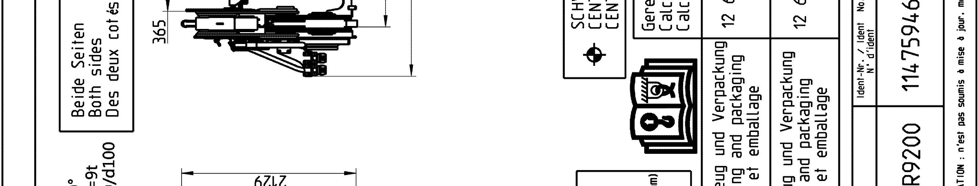
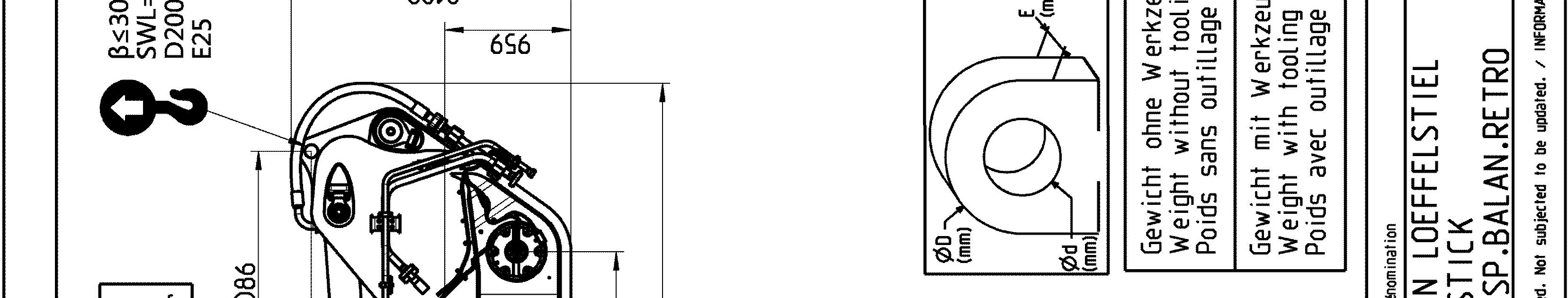
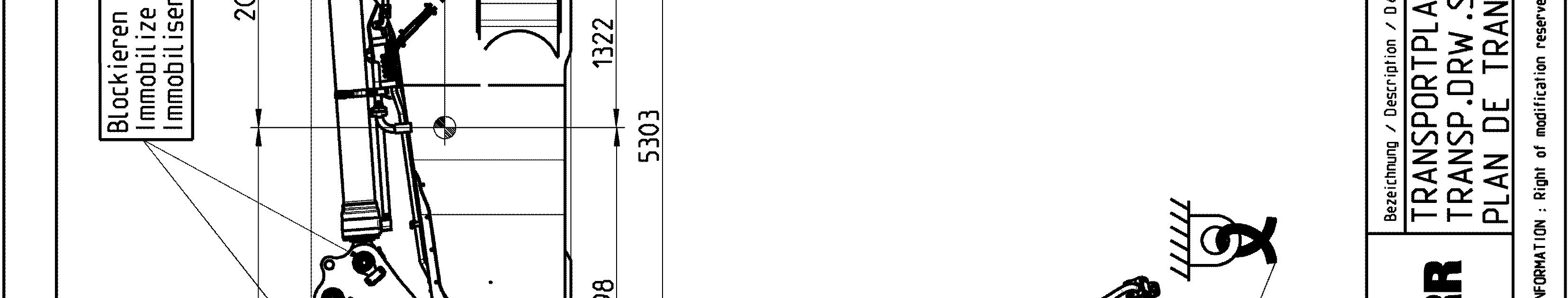
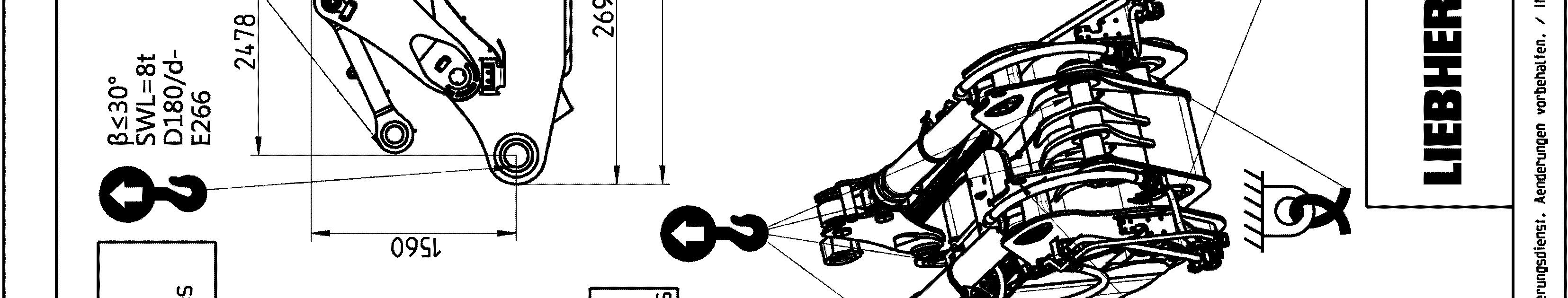
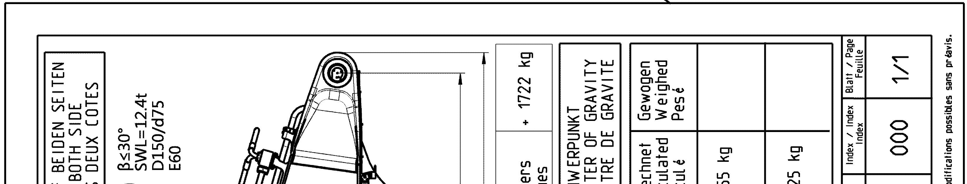
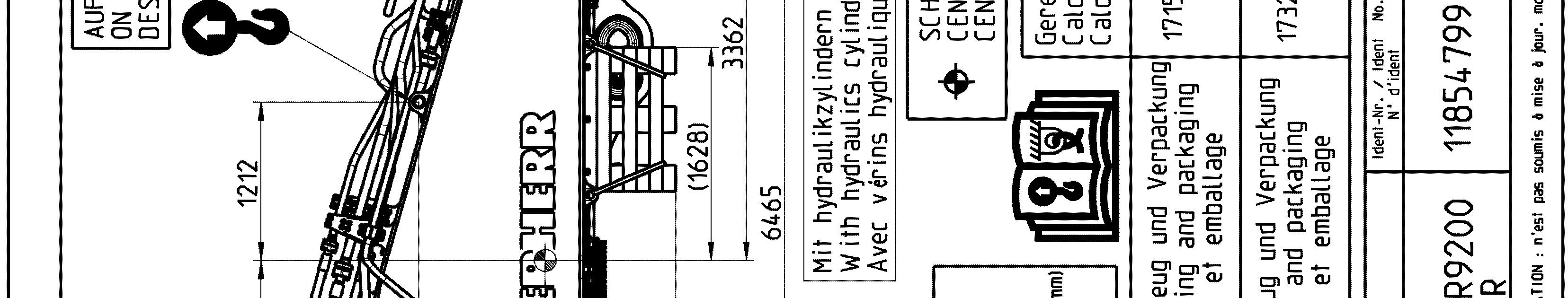
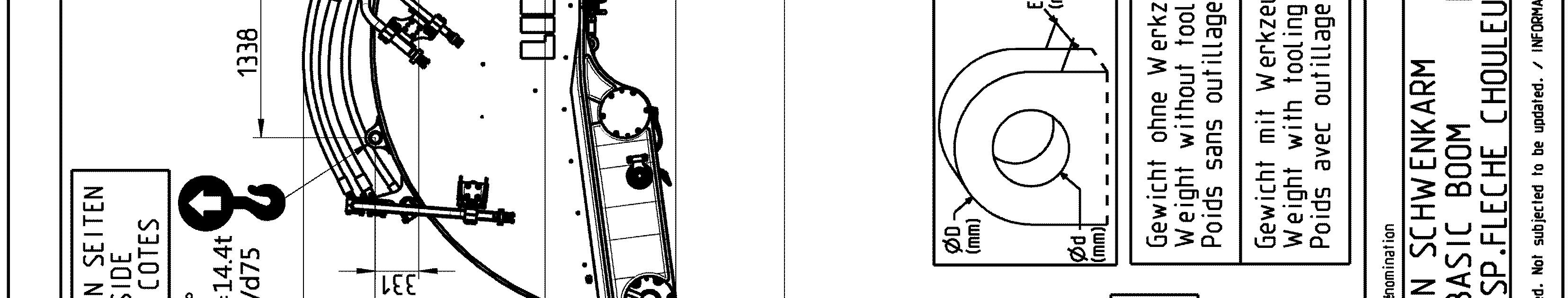
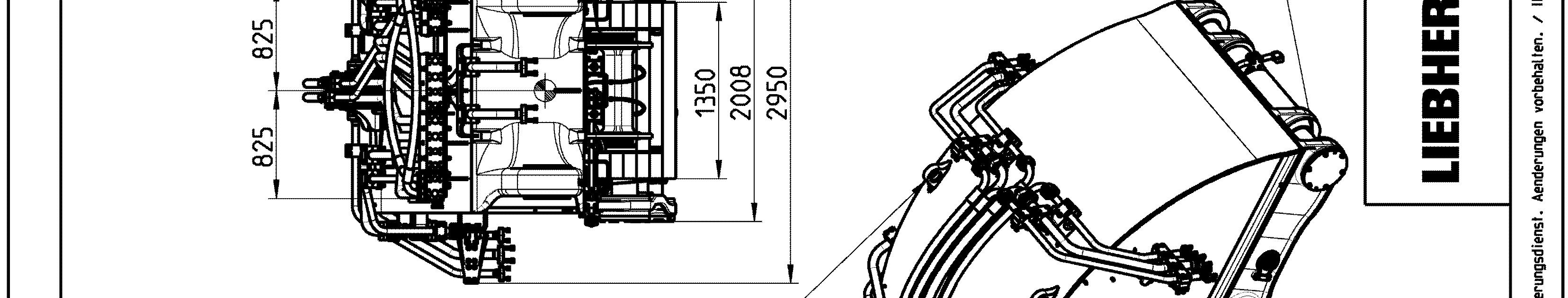
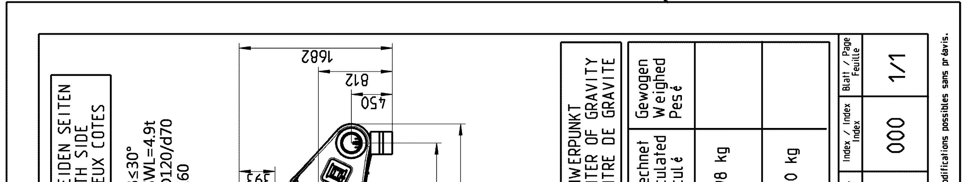
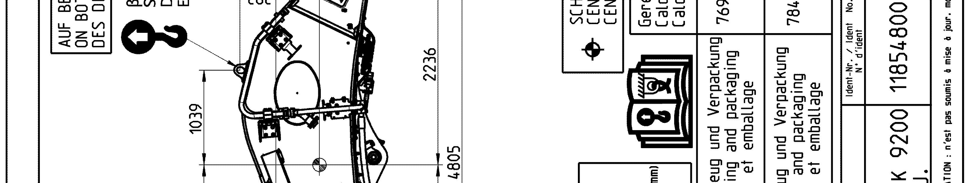
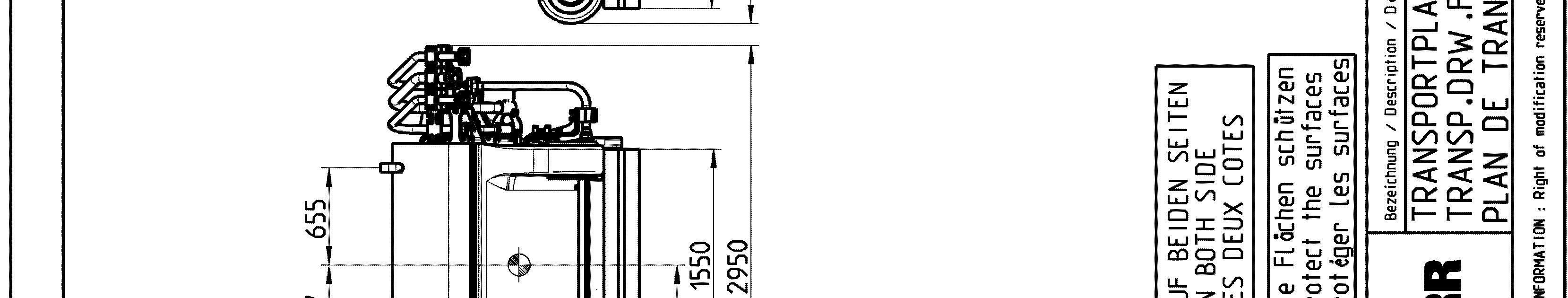
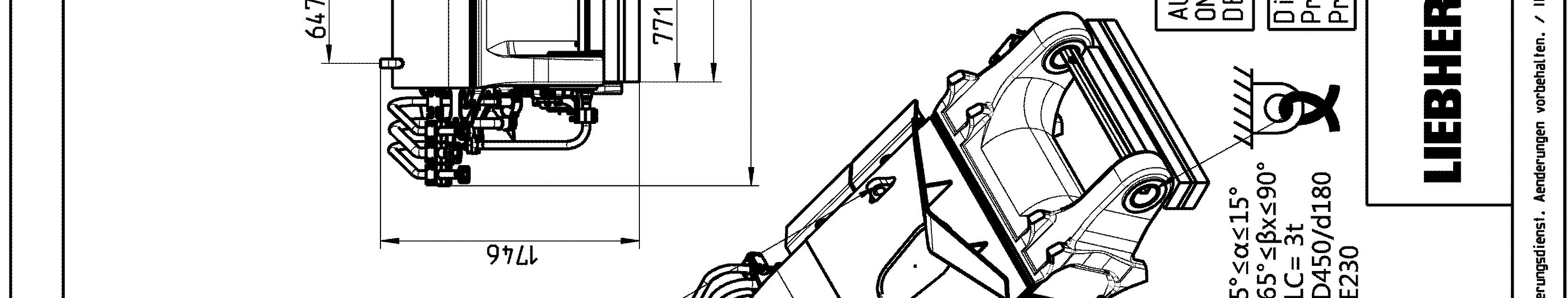
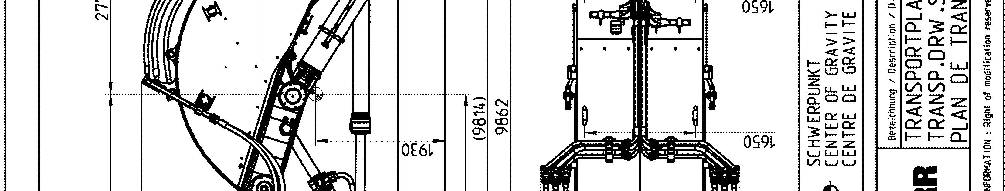
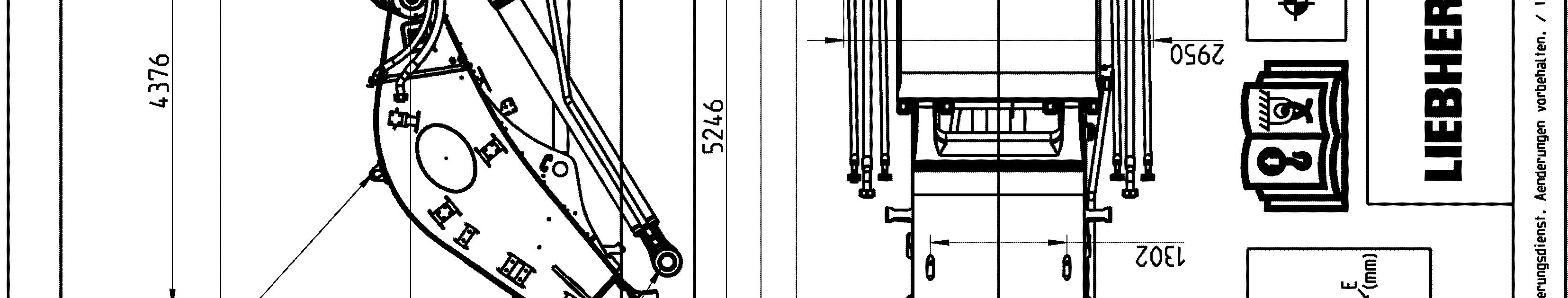
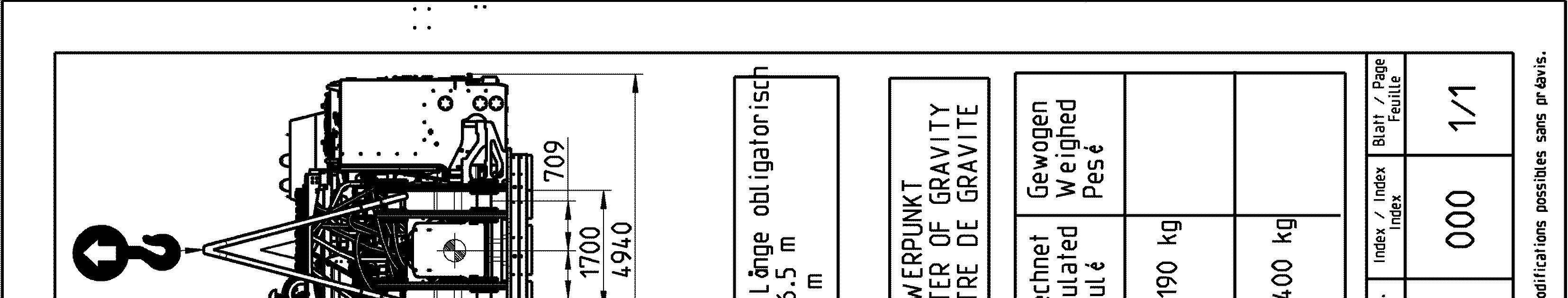
Transport drawings
The following drawings indicate the different lashing and lifting points on the elements of the excavator. Weight (with and without transport tooling and packaging), overall dimensions as well as center of gravity are also given.
The aim of these drawings is to ensure safe operation during transport, handling and storage.
Note!
The lashing and lifting points are indicated on the concerned elements of the excavator by specific labels (see § "Signs on the machine"). To be easily recognized, lifting points are painted in yellow (in red if excavator is yellow) as well.
Danger!
The lifting points given on a transport drawing for an element are designed to lift this element only and nothing else.
Never lift an assembly of several elements by the lifting points of only one of these elements.