12 minute read
Control and operation


Adjusting lumbar support (in models with pneumatic adjusting mechanism)*:
Adjust the curve of the upper and lower section of the backrest upholstery by pressing the two switches 2 at the rear of the seat.
Adjusting shock absorber*:
The shock absorption level can be adjusted to suit the actual road or terrain conditions.
Turn the handle 10 to the desired position and release it.
•Position1 = hard
•Position2 = medium
•Position3 = soft
Adjusting horizontal cushioning*:
Under certain operating conditions, you can improve the operator comfort by adjusting the horizontal cushioning mechanism. This helps reduce impact stress in travel direction on the operator as these impacts are better cushioned by the seat.
Move the handle 6 to the desired position.
•Position1 = horizontal cushioning OFF
•Position2 = horizontal cushioning ON
After the handle has been moved to position 1, ensure that is engages properly in this position: push the seat back until you hear an audible click.
Adjusting armrests:
Turn the hand wheel 5 until the armrests are in the desired position.
If required, the height can be adjusted individually for each armrest:
Remove the cover cap 4 from the seat covering.
Loosen the hex (wrench size 13mm).
Set the armrest to the desired position.
Tighten the hex nut (25Nm).
Replace the cover cap on the hex nut.
Adjusting headrest:
Adjust the headrest 16 by pulling it from the engaging mechanism. Adjust the headrest angle by pushing it forward or back.
To remove the headrest, move it to the upper stop and then pull it with force from the seat.
Seat heating:
Actuate the switch 1 to switch on the seat heating.
•Position0 = seat heating OFF
•Position1 = seat heating ON
* Model variant
3.2.4Putting on and releasing the safety belt
Danger!
The safety belt is designed to protect the operator. Before starting the machine, always fasten the safety belt. Ensure that the safety belt is not twisted when it is fastened.
To ensure your safety, check the condition, function and fastening of the belt regularly and replace any damaged parts without delay.
Fig. 3-41 Safety belt
The safety belt is automatic. It is not necessary to adjust the length of the belt. Pull the belt and buckle 2 out of the roller mount 1. If pulled out of the roller mount sharply, the belt may lock. Push the buckle into the belt lock 3 until it fastens.
To open lock 4, push down on the belt lock using your thumbs. The safety belt will slide automatically back into the roller mount 1
3.2.5Windscreen
Fig. 3-42 Locked positions of the windscreen
The windscreen can be locked in two positions. –In the position a the windscreen is closed. –In the position b the windscreen is fully opened (locked in place on the roof of the cab)
Access and equipment of the cab
Caution!
It is not allowed to work with the machine when the windscreen is in an intermediate position!
To change the position of the windscreen
Pull the lever 1 in and down to unlock the windscreen. Move the windscreen using the handle 2, secure it in one of the two positions a or b and relock using the lever 1.
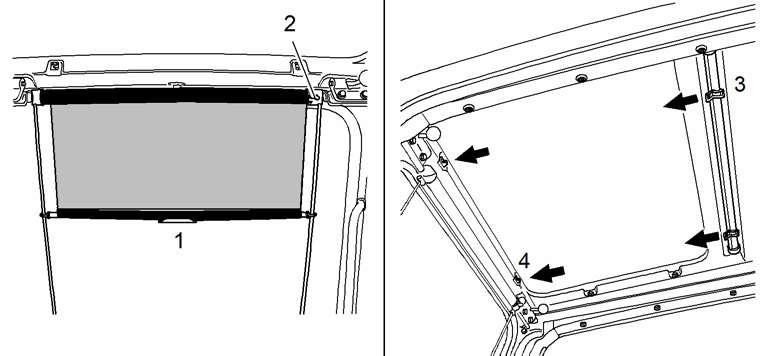
At Cab Roof
The cab is provided with two sunshades, located at the windscreen and at the cab roof window.
Manoeuvring the sunshade at the windscreen
Using the strengthening tongue 1, pull the sunshade down to the desired position. Press the red button 2, the sunshade will roll itself up.
Manoeuvring the sunshade at the cab roof
Pull out the sunshade and secure it in the holders designed for the purpose. To retract the sunshade, take it out of the holders and let it roll up slowly.
3.2.7Emergency exit – rear window
In case of emergency, remove the rubber seal 2 from all around the rear window by pulling the clip 1 on the inner side of the rear window. Thereafter push the window out.
Note!
For the machines equipped with a cab elevation, steps, ladders and hand-rails (grips) are installed to secure the descent.
Emergency exit – right window (option)
Pull the safety lever in upper position. Make sure the working attachment is immobile.
In case of emergency, remove the rubber seal 2 from all around the r window by pulling the clip 1 on the inner side of the r window. Thereafter push the window out.
3.2.8Interior lights
The dome light is controlled via the button 1
Push the button 1 to the right to switch on the light 2
Push the button 1 to the left.to switch on the spot 3
Push the button 1 into central position to switch the dome light off.
3.2.9Fire extinguisher
The interior of the cab of your machine is fitted with fixing points allowing the mounting of a fire extinguisher. These fixing points are on the right side wall of the cab, in the front area for machine models up to R954C, or in the rear corner for machine models R964C and above.
The fire extinguisher is only mounted as an option.
Note!
It is the responsibility of the owner of the machine to decide if it must be fitted with a fire extinguisher or not, considering the operating conditions and the local laws and regulations applying where the machine is used.
You can order a kit for retrofit adaptation comprising a fire extinguisher and its mounting bracket at any time at the LIEBHERR customer service.
Caution!
If your machine is fitted with a fire extinguisher: Always comply with the operating guide on the body of the extinguisher. Make sure that all the necessary inspections of the fire extinguisher prescribed by local laws and safety regulations are carried out.
3.2.10The heater and air conditioner
The cab is equipped with a heating and air conditioning system as standard. The heating and air conditioning system is used to heat, cool and ventilate the cab.
Control unit of the heating and air conditioning system
Control keys
1 – Air conditioning (cooling)
2 – Increase cab temperature
3 – Decrease cab temperature
4 – Control ON / OFF
5 – Evaporator fan speed – manual / automatic
6 – REHEAT operation
7 – Heating – manual / automatic
8 – Fresh air / recirculated air
9 – Air flap to rear wall vent OPEN / CLOSED
10 – Air flap to right control panel (8b) OPEN / CLOSED
11 – Air flap to front window, legroom CENTER / CLOSED
12 – Air flap tofront windshield, legroom CENTER / OPEN
Indications at the LCD display
13 – Air circulation
14 – REHEAT operation
15 – Air conditioning (cooling)
16 – Air flap to rear wall OPEN
17 – Air flap to right control panel (8b) OPEN
18 – Air flap to front windshield, legroom CENTER
19 – Air flap to front windshield, legroom OPEN
20 – Automatic operation
21 – Bar graph indicator for fan speed
22 – Symbol, fan speed (in manual operation)
23 – Symbol, heater operation (in manual operation)
24 – Bar graph indicator for heating output
25 – Temperature value or error code
26 – Temperature unit (°)
Note!
If the control unit recognizes a sytem error in the air conditioning circuit, a flashing error code number F1-F5 is displayed, see the section "faults and remedies", further in this manual.
Turning the control unit on
Fig. 3-48 Turning the control unit on and setting the cab temperature
Turn the system on using the key 4. The software version will be displayed for approx. 12 seconds while the control unit carries out a self test.
The heating and the ventilation of the cab are operating. The heating output and the fan speed will be controlled automatically if the AUTO symbol (20) is displayed.
Setting the desired cab temperature
The four-digit segment indicator 25 shows the desired cab temperature. Use the key 2 to increase the temperature. Use the key 3 to reduce the temperature. The adjusted temperature will remain until the next change via keys 2 and 3 is made.
Manual setting of the heating output
Fig. 3-49 Setting of the heating output and of the fan speed
Press the key 7 to adjust the heating output manually. the heating symbol 23 is displayed and will flash for 5seconds. the bar graph 24, showing the adjusted heating output, is displayed. As long as the heating symbol 23 is flashing, the heating output can be increased or reduced manually using the keys 2 or 3
Press the key 7 again, to return to automatic operation. the symbols 23 and 24 will go off, the symbol 20 is displayed again.
Manual setting of the fan speed
Press the key 5 to adjust the fan speed manually. the fan symbol 22 is displayed and will flash for 5seconds. the bar graph 21, showing the adjusted fan speed, is displayed.
As long as the fan symbol 22 is flashing, the fan speed can be increased or reduced manually using the keys 2 or 3
Press the key 5 again, to return to automatic operation. the symbols 22 and 21 will go off, the symbol 20 is displayed again.
Air conditioning operation
Fig. 3-50 Air conditioning operation and Reheat-operation
Press the key 1 turn on the air conditioning operation. the symbol 15 is displayed. the control unit now turns the airco compressor on and off automatically. the control unit automatically adjusts the fan RPM.
Press the key 1 again, to turn off the air conditioning operation. the symbol 15 is no longer displayed, the airco compressor remains off.
Note!
In case of high outside temperature, and especially if the cab has been heated up by the sun, decrease the temperature inside the cab as far as possible before turning on the air conditioner.
Open the windows and the door for a few minutes and adjust the blower fan to maximum RPM via the keys 5 and 2.
Reheat-operation
In order to achieve a quick dehumification of the cab, as an example on morning, when setting the machine into operation, it may be advisable to briefly turn on the air conditioning operation even when the heater is allready operative.
Press the REHEAT-key 6: the symbol 14 is displayed, the compressor is constantly working, the fan of the heater and airconditioner is running at maximum RPM, the air flaps at the front window and at the legroom are open, as necessary the control unit switches on the heating so to maintain the adjusted cab temperature.
As soon as the windows are completely demisted, the Reheat-operation may be exited while pressing the REHEAT-key 6 again
Access and equipment of the cab
Note!
To avoid overloading the starter motor and the batteries, turn on the air conditioning operation and the REHEAT-operation only after the engine is running. The REHEAT-operation is turned off automatically after 60 minutes.
If the machine is used for a longer period of time without using the air conditioner, press the REHEAT key 6 about every 2 weeks so to turn on the airco compressor.
Recirculated air and fresh air operation
Fig. 3-51 Recirculated air and fresh air operation
The heating and air conditioning system can work either in recirculated air operation or in fresh air operation.
Pressing the key switch 8 will alternately change from recirculated air operation into fresh air operation: in recirculated air operation:
•the symbol 13 is displayed,
•the fresh air flap 33 in the rear cab wall is closed. in fresh air operation:
•the symbol 13 is no longer displayed,
•the fresh air flap 33 in the rear cab wall is open and an amount of fresh air is admitted into the cab (about 10%, depending on the contamination of the filters 31 and 32).
Note!
The best heating, resp. cooling effect is reached in recirculated air operation!
Air repartition
The adjustment of the air flow in the cab is achieved via the keys 9 to 12 and via the partly closing and revolving louvers 8a to 8d:
• 8a on the seat console
• 8b on the right control panel
• 8c on the front windshield
• 8d on the rear wall of the cab
3-52 Air repartition in the cab
To reach a maximal feeling of comfort:
For heating the air flow must be blown into the cab via the louvers 8a, 8b and eventualy 8c. This is obtained while actuating the keys 10, 11 and eventualy 12
For air conditioner operation the air flow must be blown into the cab via the louvers 8d and eventualy 8b. This is obtained while actuating the keys 9 and eventualy 12
Note!
To defrost or dehumidify the windshield quickly, blow the whole air flow only out of the louvers 8c at the front windshield and 8b on the right control panel.
In case of very high outside temperature, preferably close the louvers 8c to avoid an unnecessary warming up of the inside air along the windshield.
Changing the temperature from °Celsius to °Fahrenheit
Fig. 3-53 Switching over °Celsius - °Fahrenheit
Press the key 8 and keep it depressed. Press the key 3 at the same time. the display of the adjustet cab temperature is changed from °Celsius into °Fahrenheit.
Pressing again the keys 8 and 3 at the same time will cause the temperature to change back into °Celsius.
3.2.11Additional standstill heater (option)
As an option, Your machine can be fitted with an additional heater mounted to the uppercarriage structure, out of the cabin. This heater is aimed to improve the starting ability of the Diesel engine and the working possibilities of the machine at very low temperatures.
This heater works with Diesel fuel and is used with the machine stopped to preheat the coolant circuit of the Diesel engine and thus the warm water circuit of the air conditioner serially installed in driver’s cab.
In addition, and depending on the low temperature range planned for the machine operation, the additional standstill heater can also serve to heat various components on the machine via water to oil or water to air heat exchangers (such as splitterbox, fuel tank, batteries compartment, ...).
Operating the standstill heater
Notice!
The standstill heater can only be operated when the ignition of the machine is turned off.
If the ignition key is turned on during operation of the standstill heater, the message "SH" is displayed on the control unit on the left control console, informing that the standstill heater is on.
Notice!
When the standstill heater is operating it is not possible to make any adjustments at the control unit of the serially mounted heater and air conditioner.
Turning on the standstill heater has following influences on the serially mounted heater and air conditioner:
•the heater function is turned on automatically, so the water circuit for the heating of the cab becomes operative.
•the fan in the cab starts running at middle RPM.
The control unit of the standstill heater
Depending on the execution of the installed standstill heater circuit and on customer’s wish, the additional standstill heater can be operated using different control units:
–Either via the control module S232. the "mini-Clock" control module S232 allows a 24 hours programming of the standstill heater.
The operation with this control unit is described thereafter.
–Or via the control module U103 With the control module U103 a programming of the standstill heater over a whole week (7 days) is possible.
Functioning of the additional standstill heater
In operation the circulating pump is started automatically and the burning is put out and on thanks to a thermostat (65°C in the water circuit), when the circulating pump is working in continuous.
To guarantee an optimal preheating of the excavator (Diesel engine, splitterbox, battery compartment and cabin), the water heater must work so long that the thermostat comes to stop the warm water circuit before the engine is started.
The start time of the heater, depends on the expected ambient temperature, and is to be programmed so that the cut-off temperature of the heater circuit is reached just before the starting time of the machine.
When the heater is turned off, the combustion will be immediately stopped, but the fan of the heater continues running for about 150 seconds (after running).
A heater re-throwing is authorised during the after running. At temperatures between –10°C and –20°C, you should start up the heater 10 or 20 minutes before start to make the starting procedure easier.
Operation of the heater using the mini-clock
1 - Key to activate the setting capabilities
2 - Time setting key backwards
3 - Time setting key forwards
4 - Key ON / OFF to activate - deactivate the preset time
5 - Current time, preset time and heating time
6 - Symbol for activated preset time
7 - Symbol for heater operation
8 - Symbol for preset time 1, 2 or 3
Setting functions on the mini-Clock
Notice!
•If no key of the control module is depressed within 15 seconds the display will return to its initial state, this means to the display of current time.
•When setting a time with the keys 2 or 3, the setting speed is accelerated when the key is kept depressed.
•Up to three preset times can be set and activated on this mini-Clock. Each preset time is deactivated after the heating period, and it must be newly activated for each new heating period (see activating / deactivating the preset time).
Setting-up for the first time:
After the first connection to the power supply all symbols on the display will start to flash. The heater cannot be turned on in this state.
The current time has to be set first:
Setting the current time:
Press key 1 of the control module for more than 3 seconds the current time is flashing.
Set the time using keys 2 and 3.
Press key 1 within 5 seconds The time is displayed the colon in the time indication area 5 flashes.
Note!
If, after the time has been set, the key 1 is not pressed within 5 seconds, the miniClock will be transferred to the mode "Setting the Heating Time".
Setting the heating time:
Press the key 1 for more than 3 seconds. The time flashes.
Press no key. the mini-Clock goes over to the mode "Setting the Heating Time". the heating symbol 7 is displayed at the control module and the heating time 5 is flashing.
Set the heating time (l0 bis 120 min) using keys 2 and 3.


