
6 minute read
Troubleshooting
Faults and remedies
Fault / errorCauseSolution
Diesel speed adjustment via operating keypad (mode and arrow keys) not functioning
Automatic idling switch S20 is activated
Operating manual
Touch the joystick or deactivate automatic idling switch S20.
Automatic idling not functioning, speed does not reduce
Servo control cannot be activated using switch
Parking brake cannot be released using switch
Slewing gear brake cannot be released using switch
No signal emits from speed sensor B12
Excavator speed adjustment electronics do not function Switch the emergency function over switch S71 in the right control panel. Set speed using switch S72. Emergency function display appears on monitoring screen. Consult customer service.
Permanent sensor signalConsult customer service
Switch S20 is deactivatedActivate switch S20
Excavator electrics faultySwitch on emergency function using switch S73 in the right control panel
Caution: Servo circuit and brake circuit can only be switched off using the safety lever. Keypad not functioning. Consult customer service.
4.2.5Work equipment
Fault / errorCauseSolution
Cylinder stretches when loadedPiston seal in cylinder defectiveOverhaul cylinder
Bearing clearance too high on equipment
Bearing points worn outReplace bearing parts
Grab / bucket does not moveValve block on tilting cylinder incorrectly switched
Add-on unit cannot be turned / rotated / operated
Switch over valve block
Release auxiliary function using switch S19 Lines are not connectedConnect lines
Auxiliary function has not been released
4.2.6Heating/air-conditioning system
Fault / errorCauseSolution
Heating not giving out warm airShutoff valves for coolant line on diesel engine closed Open shutoff valve
Engine not at operating temperatureBring engine to operating temperature
Heating fan does not operateNo power supplyCheck fuse and wiring / repair
Fan motor defectiveChange fan motor
Only low air flow in cabOutside air filter / recirculated air filter dirty
Clean air intake opening, replace outside air filter
Air vent closedOpen air vent copyright by
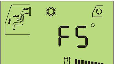
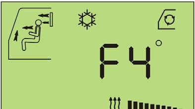
In addition, the troubleshooting in the heater and airconditioning circuit is facilitated by the upcoming of error codes in the display area of the heater/airco operation unit. These error codes inform upon the possible troubles on given components in the operation and control circuits of the heater airco/plant. They are listed below: unit:
The control unit has recognised a faulty room temperature gauge, the regulation is no longer ready for operation.
Cause of gauge error: short-circuit or interruption of gauge power supply line, defecive plug connection on gauge or on control unit, or temperature gauge faulty.
The heater / airco regulator is then only ready for operation again when the fault of the gauge has been remedied, the gauge error will then no longer be displayed! Should a gauge error occur, the regulator continues to operate to the setting which was valid before the fault was recognised.
The control unit has recognised a faulty blow-out temperature gauge, the regulation is no longer ready for operation.
Cause of gauge error: short-circuit or interruption of gauge power supply line, defective plug connection on gauge or on control unit, or temperature gauge faulty.
The heater / airco regulator is then only ready for operation again when the fault of the gauge has been remedied, the gauge error will then no longer be displayed! Should a gauge error occur, the regulator continues to operate to the setting which was valid before the fault was recognised.
The control unit has recognised a faulty reserve temperature gauge, the regulation is no longer ready for operation.
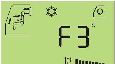
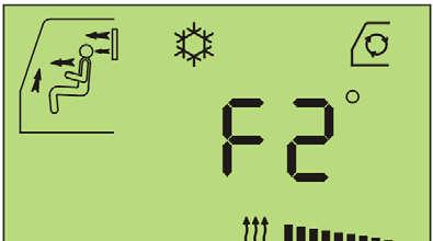
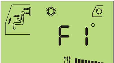
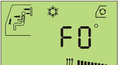
Cause of gauge error: short-circuit or interruption of gauge power supply line, defective plug connection on gauge or on control unit, or temperature gauge faulty.
The heater / airco regulator is then only ready for operation again when the fault of the gauge has been remedied, the gauge error will then no longer be displayed! Should a gauge error occur, the regulator continues to operate to the setting which was valid before the fault was recognised.
The control unit has recognised a faulty vent flap in the air duct to the front window and foot area, the regulation is once again ready for operation.
Cause of flap fault: short-circuit or interruption of the power supply line, defective plug connection on flap motor or on control unit, or flap motor faulty.
After remedying of the fault, the fault is no longer displayed. Should a flap error occur, the regulator carries on working as usual, only the middle position of the vent flap can no longer be started.
The control unit has recognised a faulty vent flap room area and front window, the regulation is once again ready for operation.
Cause of flap fault: short-circuit or interruption of the power supply line, plug connection on fan flap motor or control unit, flap motor faulty.
After remedying of the fault, the fault is no longer displayed!
Should a pressure fault or faulty magnetic coupling occur, the regulator carries on working as usual, only the magnetic coupling output is interrupted.
Data transmission from the operating feature to the control unit is faulty.
Cause of the fault: short-circuit or interruption of the data line to control unit, plug connection on operating feature or control unit.
The operating feature continues to try to establish data connection to the control unit, if the connection is once again OK
If the data transmission from the operating feature can not be established again, the ignition must be switched off, and RESET will be carried out following the restart.
4.2.7LIEBHERR particles filter system
Chart of errors on particle filter control unit A175.
LCD display messageLEDCauseRemedy
"Themo element 1 (or 2) is defective"
(or "Thermoelement 1 (oder 2) defekt")
Buzzer (H) is activated.
"ERROR idling / Temp. ignition block active"
(or "Fehler Leerlauf / Temp. Zündungssperre aktiv")
Buzzer (H) is activated.
"Error interrupt. Terminal W"
(or "Fehler Unterbr. Klemme W")
Buzzer (H) is activated.
"Pre-loading pressure achieved"
(or "Vorbeladedruck erreicht")
Buzzer (H) is activated at interval
"Main load pressure achieved."
(or Hauptbeladedruck erreicht")
Buzzer (H) is activated at interval orange + green orange + green
Defektive or interruption ot a temperature sensor orange + green red (A) + green red (A) (blink) + green
Press key E: Deactivation of the acoustic alarm (buzzer). Check temperature sensor, connect or, if necessary, replace.
Too long operation with low exhaust gas temperature (low engine load)
Press key E: Deactivation of the acoustic alarm (buzzer). Increase engine load (full load operation) decrease, carry out a filter cleaning
Idling operation too longOperate machine with higher speed.
Interruption of the of the speed logging.
Heavy loading of the particles filter through soot or ash particles.
Load on the particles filter is too high due to soot or ash particles collection.
Press key E: Deactivation of the acoustic alarm (buzzer). Check the circuit for speed logging and, if necessary, replace.
Operate the excavator with full load until the back pressure decreases.
Press key E: Deactivation of the acoustic alarm (buzzer). Clean the filter.
"Filter breakage or pressure line clogged" (or "Filterbruch oder Druckleitung zu")
Buzzer (H) is activated at interval
"Call service" (or "Service rufen")
All LEDblin k
Defective particle filter (By-Pass) or blocked pressure line or leak in the pressure line
Press key E: Deactivation of the acoustic alarm (buzzer). Check particle filter module, if necessary, or replace filter module, if necessary or eliminate blockage in the pressure line or eliminate leak in the pressure line
The pre-set operating hours until the next service / cleaning of the filter module has expired
Press key E Set back the operating hours counter.
For Filter maintenance see the chapter 5 "Maintenance" copyright by
4.3Fuses and relays
F19 100 ACircuit breaker on Kl30 - preheating
F20 50 ACircuit breaker on Kl30 - main circuit
F22 7,5 AFuse on Kl30 - reserve (hazard warning system on wheel excavat.)
F31 7,5 AFuse on Kl15 - heater and air conditioning system
F337,5 AFuse on Kl15 - control circuit for refuelling pump (optional extra)
F34Fuse on Kl30 - reserve for options
F35Fuse on Kl30 - reserve for options
F3620 AFuse on Kl30 - power circuit for refuelling pump (optional extra)
F36-215 AFuse on Kl15 - cut off of cylinder movements (option)
F36-37,5 AFuse on Kl15 - for additional heating (option)
F3720 AFuse on Kl30 - heater and air conditioning system
F10950 ACircuit breaker on Kl30 - special equipments and headlights
F11050 ACircuit breaker on Kl30 - power supply of PLD system
F112 7,5 AFuse for E50
F115 7,5 AFuse on Kl15 for safety mode
F116 7,5 AFuse on Kl30 - controller of PLD system
F117 7,5 AFuse on Kl15 - PLD system
F122 7,5 AFuse on Kl30 - preheating signal for PLD system
F1337,5 AFuse on Kl30 for hydraulic adjustable cab (option)
F25325 AFuse on Kl30 for additional headlights on attachment (option)
K10-1 Relay / additional headlights on counterweight
K56Relay / preglow fuel
K66-1 Relay / cut off of cylinder movements (option)
K66-2Relay / cut off of cylinder movements (option)
K127 Relay / engine RPM adjustment in safety mode
K128Relay / engine start in safety mode
K288Relay / terminal 15
K302Relay / engine preglow
K359Relay / extra heating
K41520 ARelay / additional attachment headlights (option)
4.3.2A1010 Plate
All other fuses are situated in the left cont
Danger
Incorrect or bypassed fuses do not offer the machine's operator or the electrical system the required degree of protection.
Only use original fuses.
Never bypass electrical fuses.
If required, order replacement fuses from LIEBHERR.


