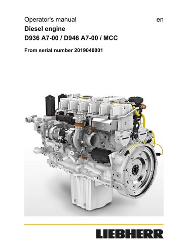
3 minute read
MaintenanceOperator's manual


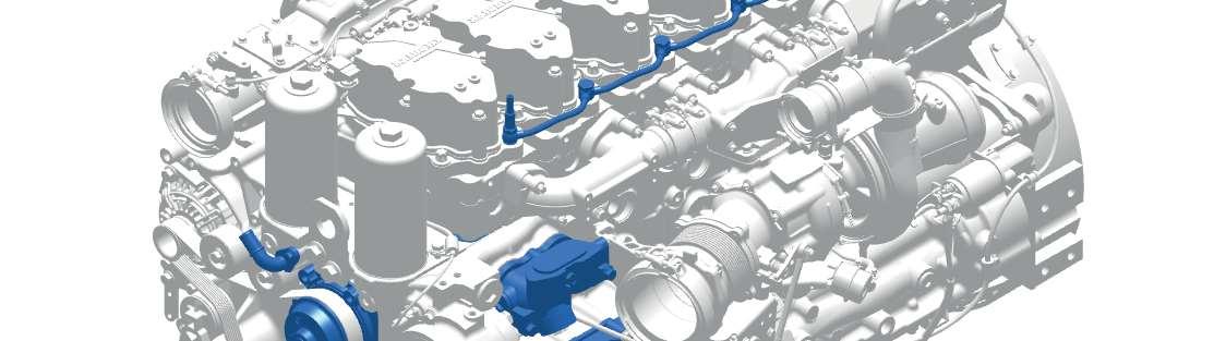
Cylinder head
Tighten the ABS adjusting screw 5 with 0.3 Nm. ABS piston 9 goes to the limit stop.
Tighten the ABS piston 9 with 45 Nm.

Pull out the feeler gauge.
Press on the ABS valve bridge 1 with your hand. ABS piston 9 goes to the limit stop. The push rod has play.

The valve clearance for the ABS adjusting screw (optional) is set.
Repeat the process for all cylinders.
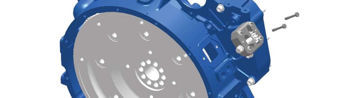
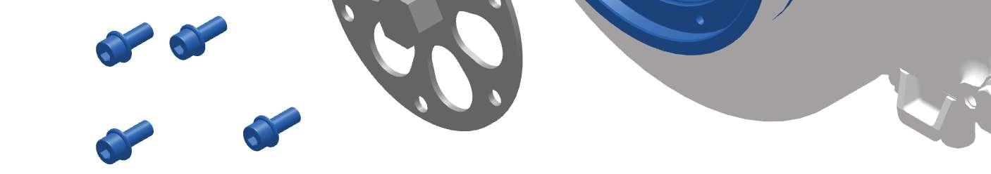
Removing the turning device from the flywheel housing


Cylinder head
Removing the turning device from the crankshaft
1 Turning device 2 Crankshaft Remove turning device 1 from crankshaft 2
Installing the cylinder head cover
Tensioning instruction for M4 hex nut

Tab. 20: Tightening instruction 12977315_001


Tighten the hex nuts 7 according to the tensioning instruction. Install the cylinder head cover 2.
Tighten the external hex bolts 1.
Tighten the external hex bolt 3.
Connect the electrical line to the electrical plug connection 4.

5.6Cooling system
5.6.1Checking the cooling system and heating system for leaks and damage
WARNING
Hot cooler parts and hot coolant!
Serious burns possible.
Make sure that the engine has cooled down to 20 °C or ambient temperature before starting the maintenance activities.

Wear protective gloves and safety goggles.

Check components for leaks.
Check components for damage.
Check the expansion tank (device side), see documentation from the device manufacturer. Check the coolant line connections (device side), see documentation from the device manufacturer.
Check the completeness of all components, see documentation from the device manufacturer. If components are leaking or damaged: Do not start engine.
Replace damaged components, see repair instruction.
5.6.2Checking the coolant level
WARNING
Hot cooler parts and hot coolant!
Serious burns possible.
Make sure that the engine has cooled down to 20 °C or ambient temperature before starting the maintenance activities.
Wear protective gloves and safety goggles.
For procedure to check the coolant level, see documentation from the device manufacturer. If the coolant level is too low or too high: Do not start the engine.
Refill the coolant, see documentation from the device manufacturer. (For more information see:
5.6.3 Checking the concentration of the antifreeze agent in the coolant, page 97.) (For more information see: Filling the coolant, page 101.)
5.6.3Checking the concentration of the antifreeze agent in the coolant
Checking the concentration of theantifreeze agent
WARNING
Hot cooler parts and hot coolant! Serious burns possible.
Make sure that the engine has cooled down to 20 °C or ambient temperature before starting the maintenance activities.
Wear protective gloves and safety goggles.
Open sealing cap on filler neck. See documentation from the device manufacturer. Take a coolant sample.
Analyze the sample using a suitable test method.
If necessary, correct the mixing ratio of the antifreeze agent in the coolant.
Correcting the concentration of the antifreeze agent
If necessary, calculate the missing quantity of antifreeze agent according to the calculation formula (see: fig. 81, page 98).
NOTICE
Concentration of the antifreeze agent too high! Damage to engine.
Make sure that the concentration of the antifreeze agent is between 50% and 60%.
Fig. 81: Calculation formula for refilling quantity of antifreeze agent, example 29 vol.%
1 Coolant fill quantity in liters 3 Refilling quantity of antifreeze agent in liters
2 Measured concentration in vol. %
Drain the calculated refilling quantity from the cooling system. For coolant fill quantity, see documentation from the device manufacturer. Fill the calculated refilling quantity of the antifreeze agent.
5.6.4Replacing the coolant
Make sure that the following prerequisites are met:
–Heating valves are open.
–A collection container with the necessary capacity is available.
–A suitable drain hose is available, see documentation from the device manufacturer.
–The necessary quantity of coolant is available, see documentation from the device manufacturer.
Draining the coolant on the device
Drain the coolant via the device side outlet, see documentation from the device manufacturer.
Draining the coolant on the engine
Make sure that the following prerequisites are met: Heating valves are open.
A collection container with the necessary capacity is available. A suitable drain hose is available, see documentation from the device manufacturer.
The necessary quantity of coolant is available, see documentation from the device manufacturer.
Tab. 21: Special tool
WARNING
Hot cooler parts and hot coolant!
Serious burns possible.
Make sure that the engine has cooled down to 20 °C or ambient temperature before starting the maintenance activities.
Wear protective gloves and safety goggles.
NOTICE
Escaping coolant!
Injuries
Avoid skin contact with coolant. Follow the manufacturer's instructions.
When mixing coolant, wear rubber gloves and safety goggles. Wash coolant in the eyes or on the skin off with water immediately.
2
3
Loosen the end cover on the device side compensation tank slightly. Excess pressure escapes from the cooling system.
Unscrew protecting cap 1
Connect drain hose 3 to the drain valve 2.
Let the coolant run into the collection container through the drain hose. When the coolant has drained completely: Tighten protecting cap 1
Filling the coolant
Fill the coolant via the device side filler neck. (For more information see: Correcting the concentration of the antifreeze agent, page 98.)
Fill cooling system up to maximum.
Place the sealing cap on the compensation tank and close it.
Start the engine.
Let the engine warm up.
Coolant temperature > 80 °C.
Turn off engine. (For more information see: 4.3 Turning off the engine, page 50.)
Let the engine cool down.
Check coolant level. (For more information see: 5.6.2 Checking the coolant level, page 97.)
If the coolant level is too low or too high: Correct the coolant level, see documentation from the device manufacturer.