9 minute read
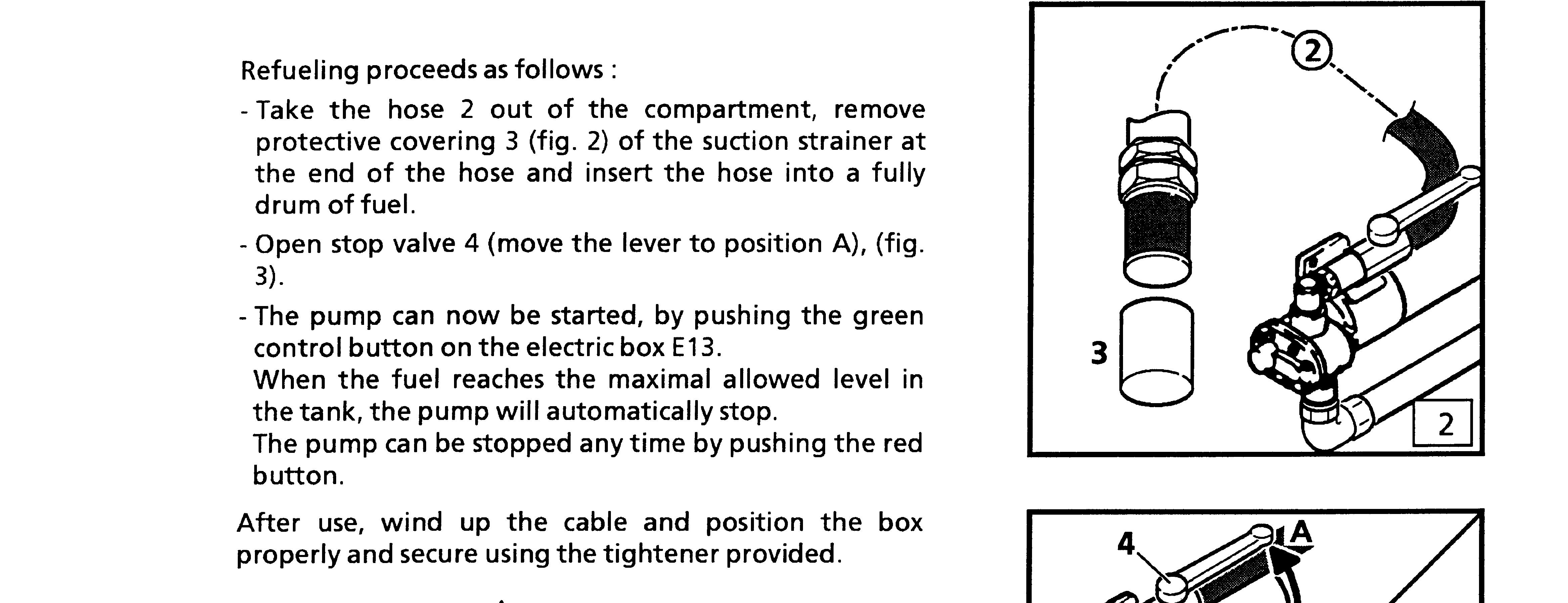
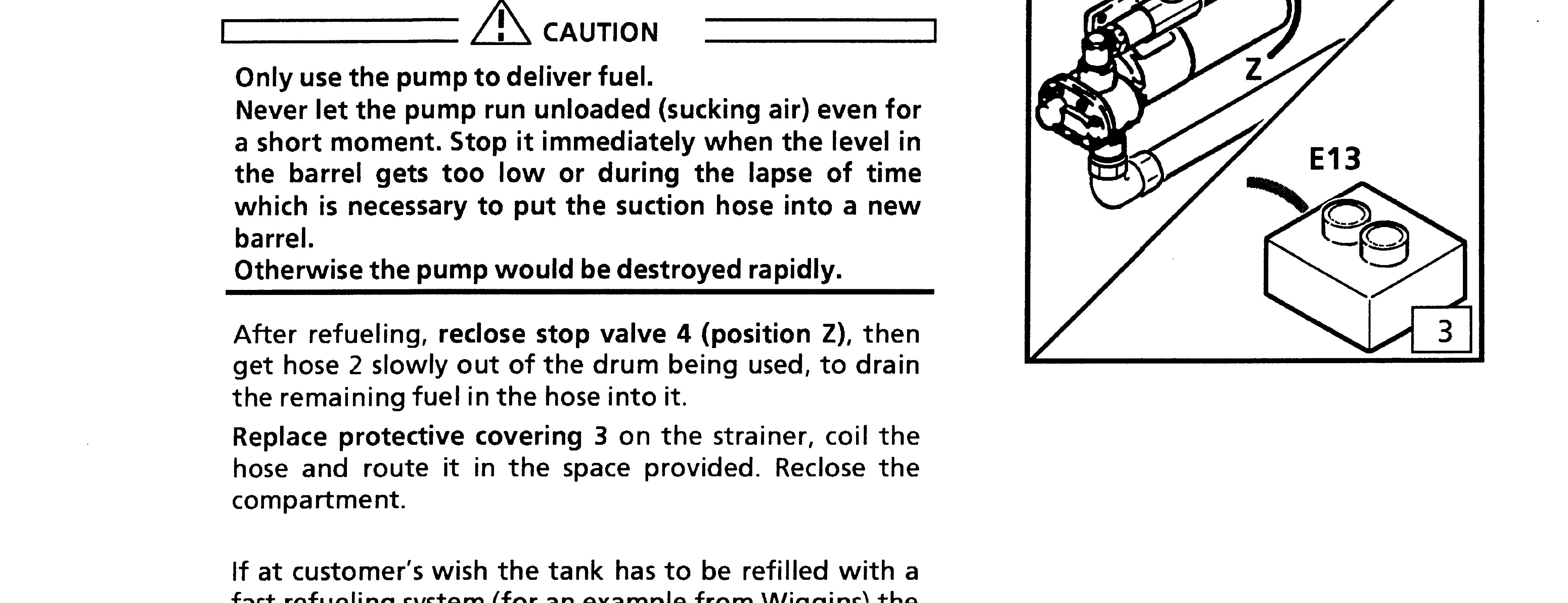
Operation Manual


The blow out direction of the air flow can be adjusted while opening or closing the 4 following ventilation flaps:
Adjustable Operator's Cab with 2-Stage Elevation
(Hoist Frame with Double Parallelogram)
Technicaldata
Denomination:CABLIFT8×8M
MaximalOilPressureforCabAdjustmentCylinders:190bar
MaximalOilFlowforCabAdjustmentCylinders:42l/Min
Manufacturer: .......................................................................... JOHSMÖLLERS
MASKINFABRIKA/S
OverJerstal6500Vojens
Sweden
PURPOSE OF THE 2 - STAGE ELEVATION (Adjustable on hoist frame with double parallelogram)
With this elevation (hoist frame with double parallelogram), the operator's cab can be adjusted through two positional elements coming from ground level, forwards and upwards.
Both positional elements can be controlled independently of each other via a joystick in the operator's cab.
They are subsequently designated:
Cab side element I, Slewing platform side element II
The 2 - stage cab elevation offers the following advantages:
Safe entry and exit when the cab is on the ground,
A good view of the working area, especially when loading ships or goods-wagons or when working with obstacles, ... .
SAFETY GUIDELINES WHEN WORKING WITH THE ADJUSTABLE CAB WITH 2-STAGE ELEVATION
(Adjustable on hoist frame with double parallelogram)
Only climb in and out of the cab when it is on the ground.
Familiarise yourself with the emergency exit through the front window.
The windshield is used as an emergency exit and may not become blocked by placing any items against it, e.g. a front guard!
If a front guard is necessary, it should be arranged so that an emergency exit through the front window is still possible .
Put on the safety belt immediately on entering the cab and close the cab door before starting the engine.
Familiarise yourself with the cab's movements using the control lever before operating the cab elevation . Check the emergency lowering function every day before beginning work.
Check that the shut-down for the slewing gear and the stick retraction are functioning every day before beginning work or that they respond promptly (see page 10).
Only adjust the cab when the machine is stationary.
Presence of a third person in the danger zone of the excavator is not to be tolerated during the adjustment procedure of the cab.
Working with the machine, as well as elevating and lowering the operator's cab is only permissible if the undercarriage has been stabilised.
Travel in the machine should fundamentally only be carried out with the cab retracted and in the upper position, thus. with the slewing platform side element of the elevation fully raised and the cab side element fully lowered.
With travel movements, please ensure that: the working attachment is load-free and retracted as far as possible , the travel surface is even, stable and free of any obstacles.
The cab elevation is designated for a maximum 160 kg .
It is forbidden to carry passengers on the outside of the cab.
Never drive the cab underneath a load in the clamshell or the lifting hook. It can be hazardous if the load drops from the clamshell or the lifting hook.
Please be fully aware of the danger that could occur during operation of the cab elevation and the lift frame, e.g. collision with parts of the undercarriage or with the load in the clamshell or the lifting hook.
Be aware of the location of electrical lines around the working area and maintain sufficient distance at all times between the cab, elevation or other machine parts and electrical overhead cables.
This is very hazardous!
Familiarise yourself with the safety distances which must be maintained and do not undertake any jobs where the necessary distance from electrical overhead cables can not be attained.
Never use the cab elevation as a crane.
The cab elevation should never be used during thunderstorms.
Hold the cab as near as possible to the excavator's slewing centre in order to reduce vibrations and swings in the cab as much as possible. Raise the slewing gear side element completely, and adjust the height with the cab side element.
In the event of an unbalanced position - via a main block valve that has jammed, or a burst hydraulic hose, release the control lever immediately. Then shut off the diesel engine to cut off the oil supply. The cab will remain in position via the pipe-break protection.
The cab can then be lowered via two emergency lowering switches located in the cab.
Two emergency lowering switches are also arranged on the basic machine, and manual operation of both emergency lowering valves is also possible (see also page 9).
Never continue operation of a machine with a malfunction until the malfunction has been remedied
Always maintain visual contact with the undercarriage when lowering the cab.
The Control Elements
H83 Control light / Cut-off of swing movements
S78-1 Cab emergency lowering (Cab side element)
S78-2 Cab emergency lowering (Uppercarriage side el.)
U45 Joystick for cab position adjustment.
. The movements of the cab are controlled via the electronic servo-control joystick U45 on the right control console (fig. 47).
. The joystick U45 is operative only as long as the push button S370 at the rear of the left control console (fig. 46) is maintained depressed.
Operation
ADJUSTING THE OPERATOR'S CAB
. During adjustment of the cab, the push button S370 (fig. 46) must remain pressed down.
Movements of the uppercarriage side element
. A forward application of joystick U45 (0) will induce a downward movement of the uppercarriage side element (fig. 48).
. A backward application of joystick U45 (p) will induce an upward movement of the uppercarriage side element.
Movements of the cab side element
. An application of joystick U45 to the left (m) will induce a downward movement of the cab side element (fig. 48).
An application of joystick U45 to the right (n) will induce an upward movement of the uppercarriage side element.
Caution
If the cab is lowered to ground level while the undercarriage is in the supported condition, it is imperative that sufficient ground clearance is maintained under the cab.
If this is not observed, the cab elevation could sustain damage when the outriggers are being retracted.
EMERGENCY LOWERING OF THE CAB:
Even with the Diesel engine shut off, or with a malfunction in the hydraulic system, the cab can be lowered downwards all the way to the ground, on three different manners: a) via the two switches S78-1 and S78-2 on the control panel of the cab (fig. 45), b) via the two switches S79-1 and S79-2 in the switch cabinet on the front side of the hydraulic tank (fig. 49 and 50), c) via the two solenoid valves Y 204-1 and Y 204-2 behind on the fixing support of the adjustable cab (fig. 51).
By pressing either switch S78-1 or S79-1, the cab side element will be lowered. By pressing either switch S78-2 or S79-2, the uppercarriage side element will be lowered.
In the event of a power supply failure on the excavator, the cab side, or the slewing platform side element can also be lowered down via direct actuation of either solenoid valve Y 204-1 or Y 204-2
To achieve this, a suitable pin (Ø max. 4mm and minimum length 70mm) must be inserted into the opening of the solenoid part of the valve (fig. 51). When this pin is pushed the valve can be directly operated.
Caution
Depending on obstacles that could possibly arise around the cab area and the possible setting down positions on the ground, it should be considered before emergency lowering of the cab, as to which order the 2 elements are to be lowered.
SHUT OFF OF THE SWING MOVEMENTS:
The operation of the swing gear is automatically shut off as soon as a risk of collision occurs between the base of the cab and the undercarriage .
In this case, the warning light H83 (fig. 52) lights up. The control of the swing gear will become possible again as soon as the cab has been adjusted to a high enough position.
Caution
Every day, before beginning to work, check that the shutoff of the swing movements is functioning and that it responds promptly.
Maintenance of the cab elevation is limited to the essentials, with regular visual checks of the structure and the elevation's hydraulic system.
Determined malfunctions are to be remedied immediately.
Additionally, the machine should be washed periodically. Worn seals, cracks and other faults are difficult to spot on a dirty machine.
All repair work on the elevation is to be carried out while the cab is positioned on flat and even ground .
Depending on the repair, all the necessary parts are to be supported. Only walk underneath the parts if they are supported.
Structure of the cab elevation
All bearing points are lubricated via the central lubrication system. Each bearing point should be checked visually for the exuding of grease every day.
Visually check the condition of the cab elevation daily, and inspect for parts that may have broken off, fallen off or are worn.
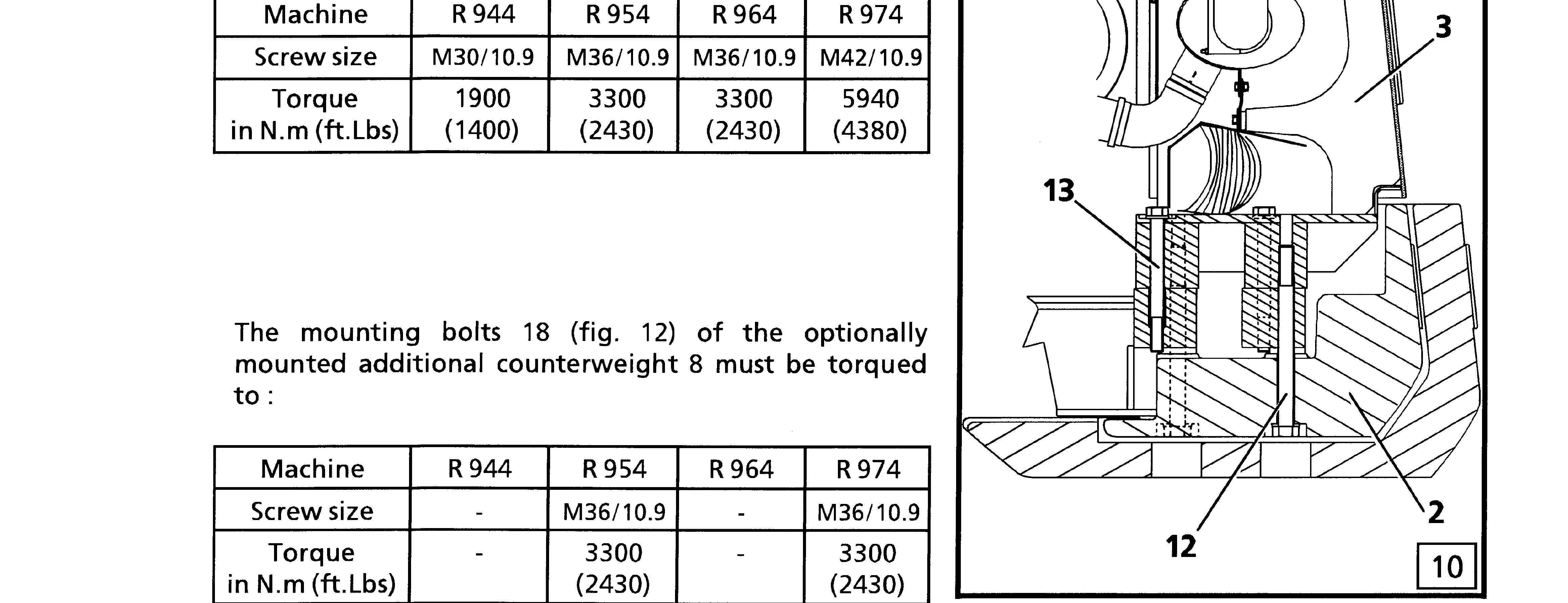
The fixing screws on the base of the cab elevation for the uppercarriage structure should be checked for secure fastening every 500 operating hours and retightened.
The tightening torque of these M30 fixing screws is 2300 Nm.
Modifications such as drilling, burning or welding on components that serve as a power transmission to the elevation may only be carried out by the manufacturer or by an authorised contracted workshop .
Never stick your fingers into the bolt boreholes when replacing bolts or when carrying out other tasks. Use a suitable pin to straighten the boreholes.
Hydraulic system for the cab elevation
Before working with the machine, a visual check of seals for the cab elevation's hydraulic system must be carried out daily.
Modifications to the adjustment of the elevation's hydraulic components may only be carried out by the manufacturer or by an authorised contracted workshop.
Before each intervention in the hydraulic circuit, the control pressure and the dynamic pressures in the elevation's working circuit are to be released as follows....
bring the start key into the contact position (safety lever must be in the down position), switch on the servo-control circuit for cab adjustment while depressing the push button S370. briefly actuate the joystick U45 in all 4 directions (keep S370 pressed down).
Release of pressure is resulted despite the pipe-break protection valves installed on the hydraulic cylinders of the cab elevation . then release the push button S370 and start key ....and release the tank's internal pressure as described before in this operation and maintenance manual .
Every 1000 operating hours: thoroughly wash the entire machine, then visually inspect the hydraulic hoses and hydraulic components for leaks, damage or other faults. visually inspect the steel structure parts for crack formations.

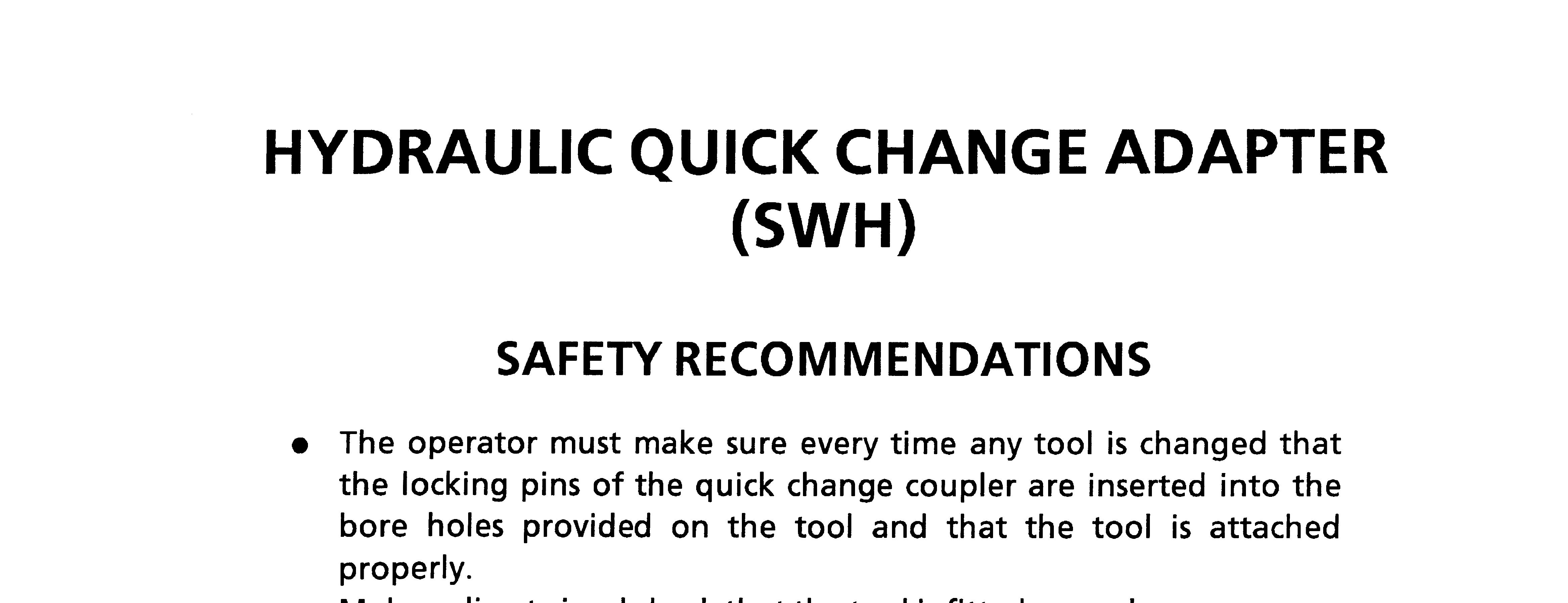
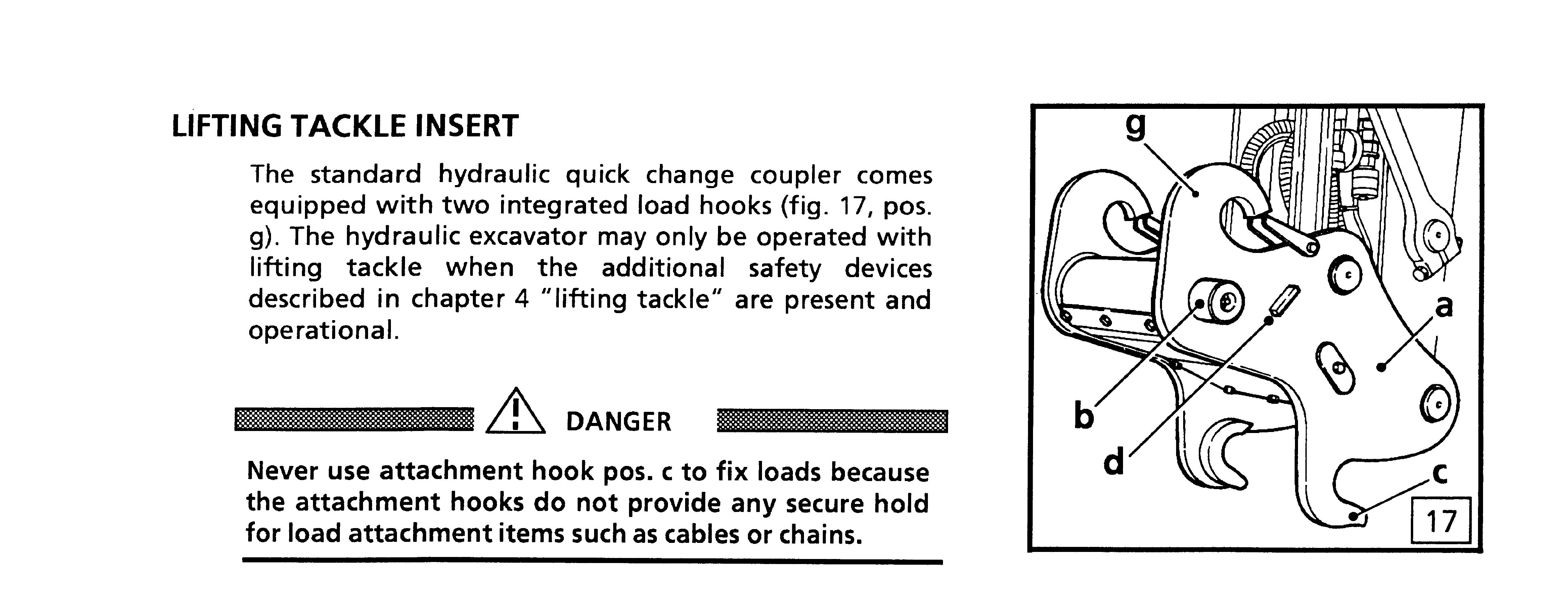
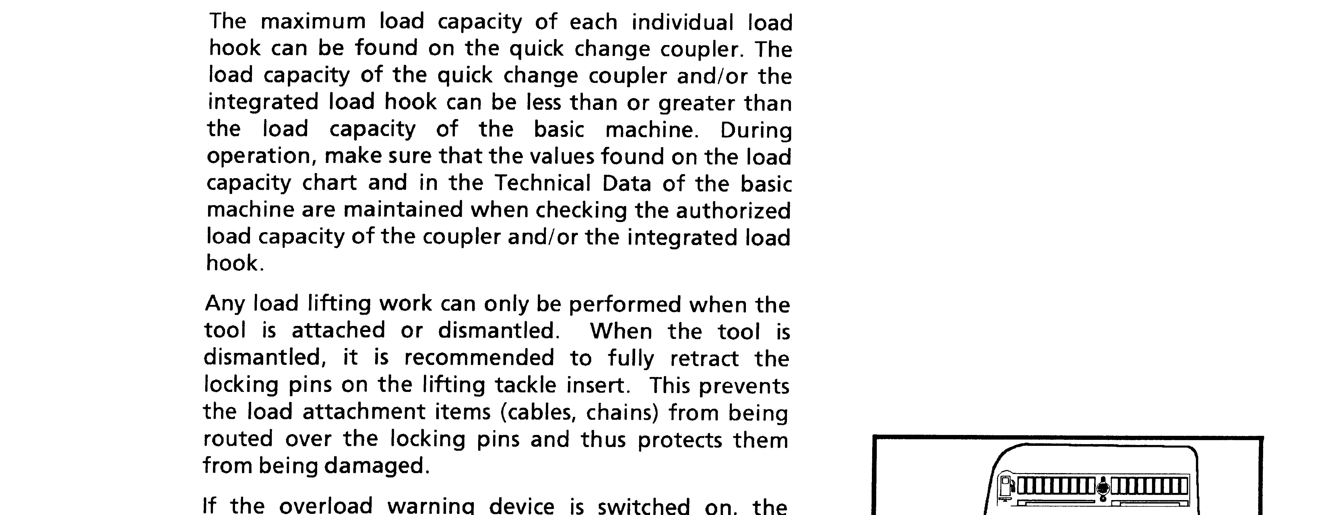
HYDRAULIC QUICK CHANGE COUPLER (SWH)
a coupler b locking pins (extended) c attachment hook for tool d stop g load hook
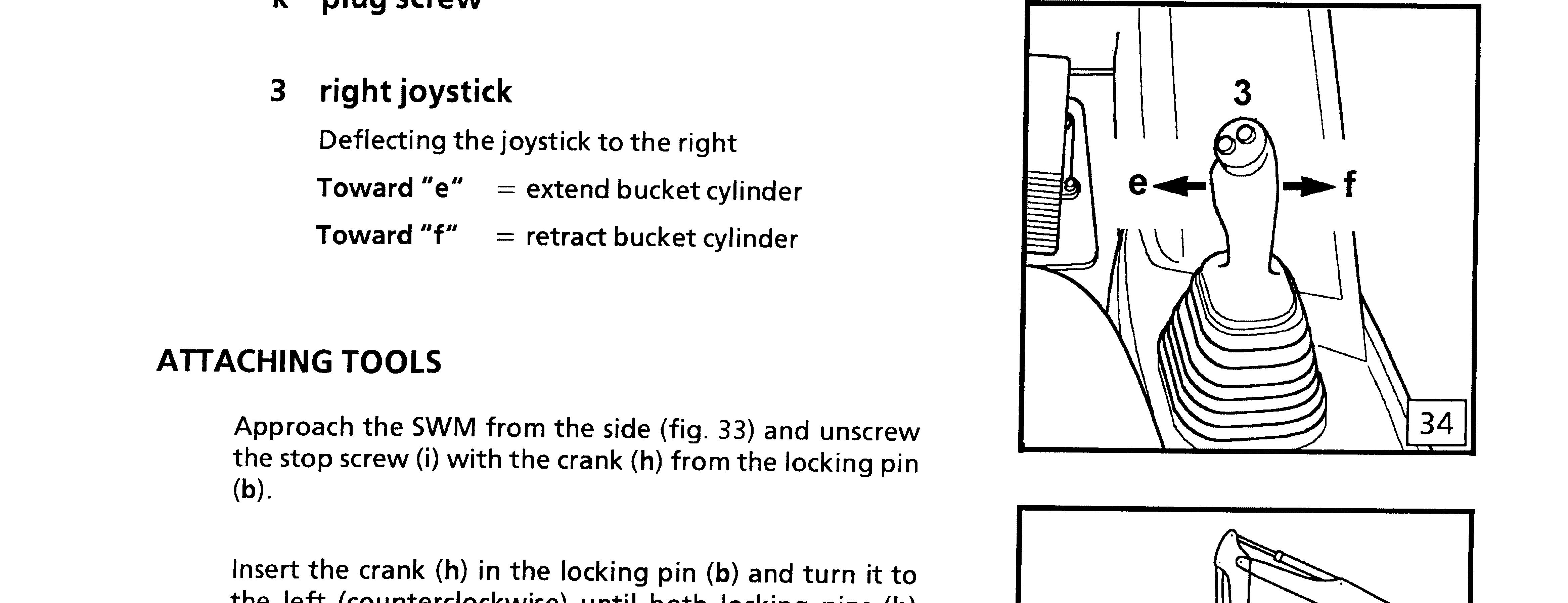
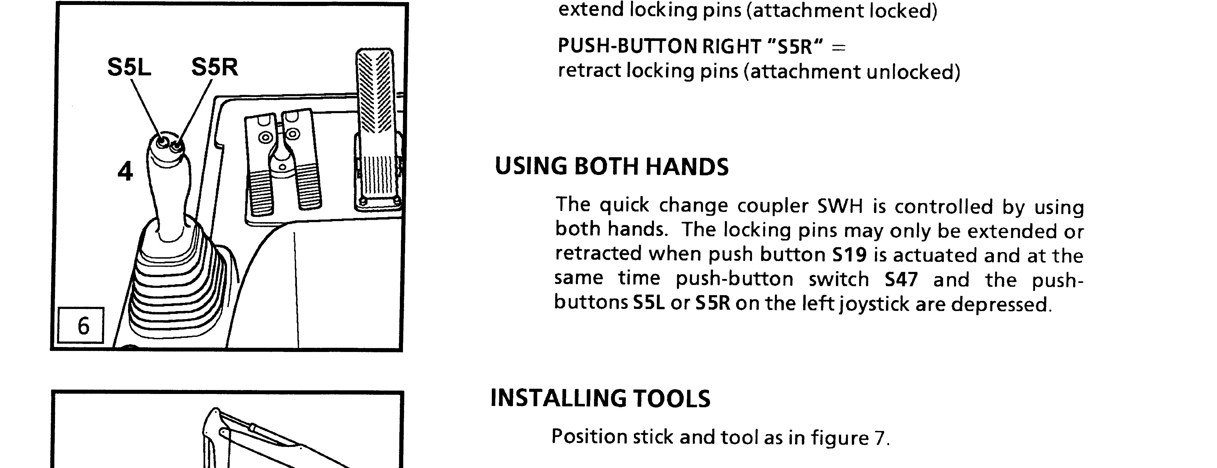
3 right joystick
4 left joystick with push-buttons left / right
S47 push-button switch or key switch
S19 push button for grapple rotation drive
TECHNICAL DATA
Maximum operating pressure 100 bar.
PUSH BUTTON S19 (fig. 3)
The hydraulic additional attachment function for grapple rotation drive is actuated via push button S19 (indicator light in the button lights up).
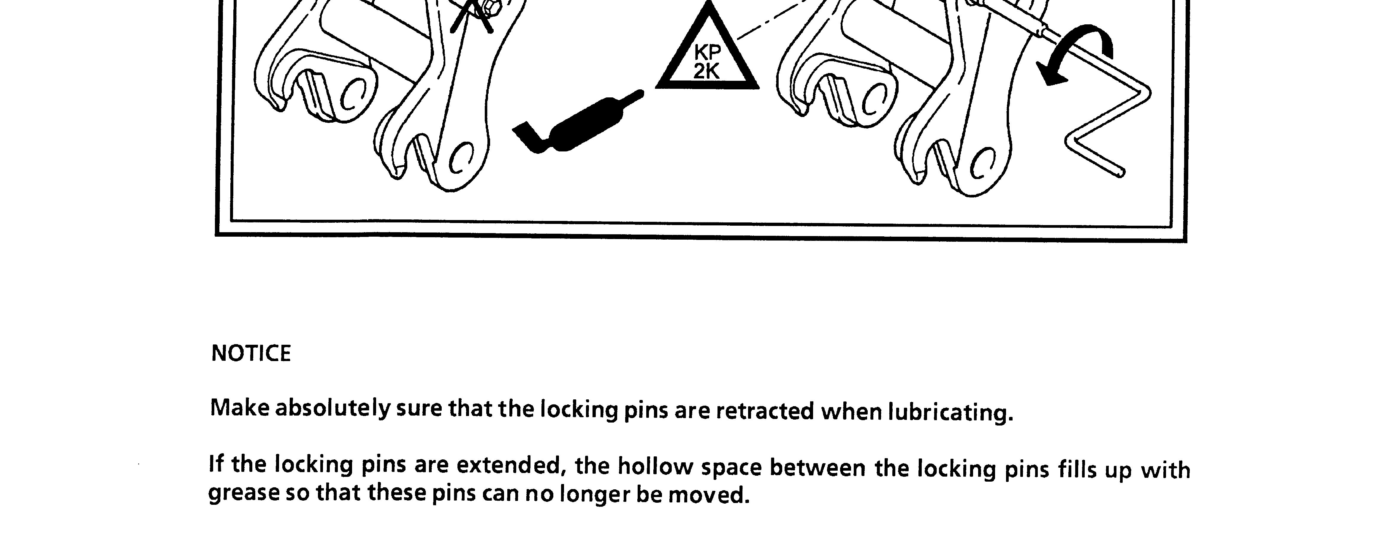
If this symbol appears on the screen, the pins are retracted (tool unlocked)
DANGER
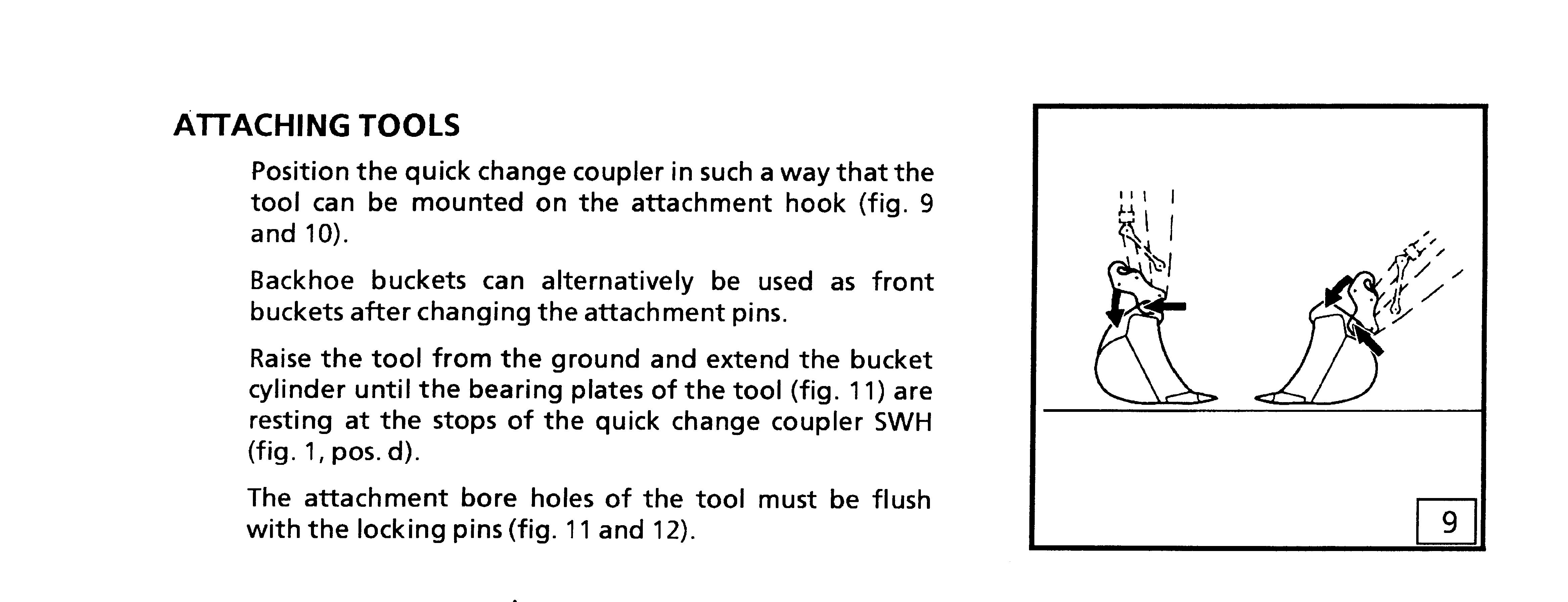
The attachment is only connected to the attachment hook
PUSH-BUTTON SWITCH WITH KEY S47 (fig. 4)
POSITION "0"
Zero position; it is not possible to actuate the locking pins of the quick change coupler SWH.
POSITION "I"
When push button S19 is on, the locking pins can be actuated if the switch S47 is in position "I".
- with the key switch S47: turn the key clockwise to position " I " and then depress and keep the key depressed.
- with the push button S47: press down and hold the button depressed.


Functional check out of quick change coupler
Daily, at machines operating start, check out the quick change coupler functions as well as its warning light and buzzer in the cab.
This verification can also be done at the first daily tool change. Proceed as below :
Start the Diesel engine and let it run on low idle.
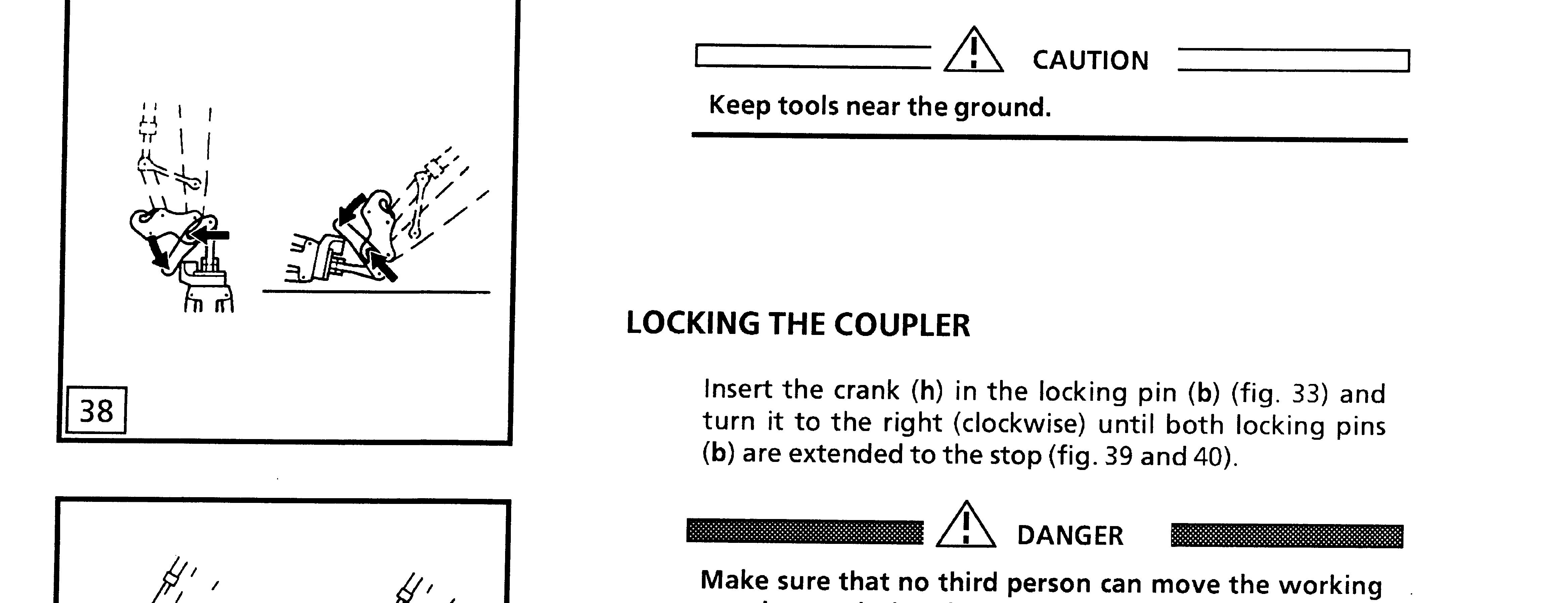
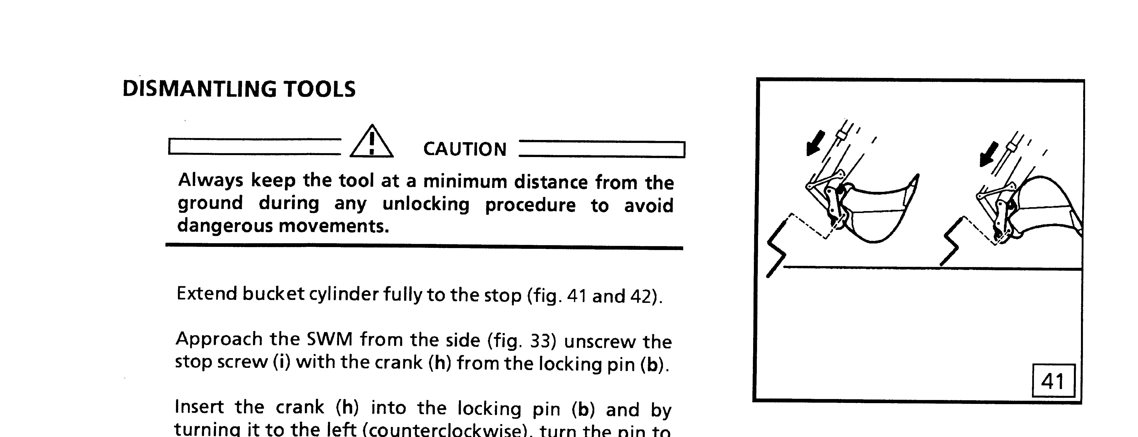
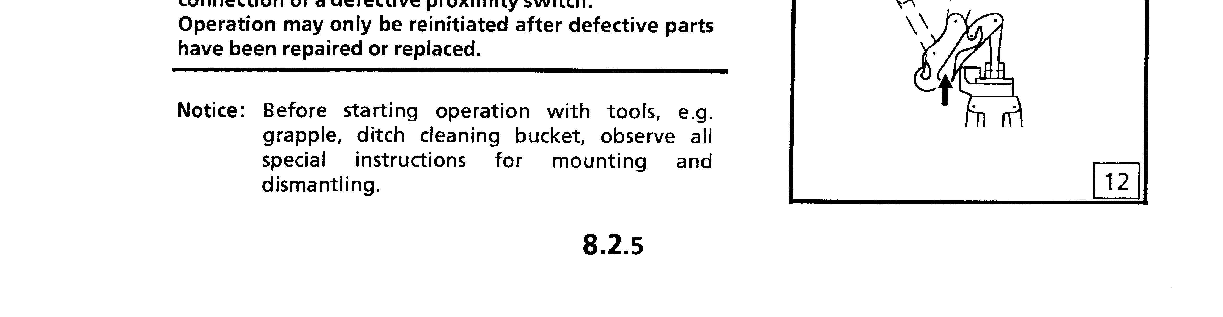
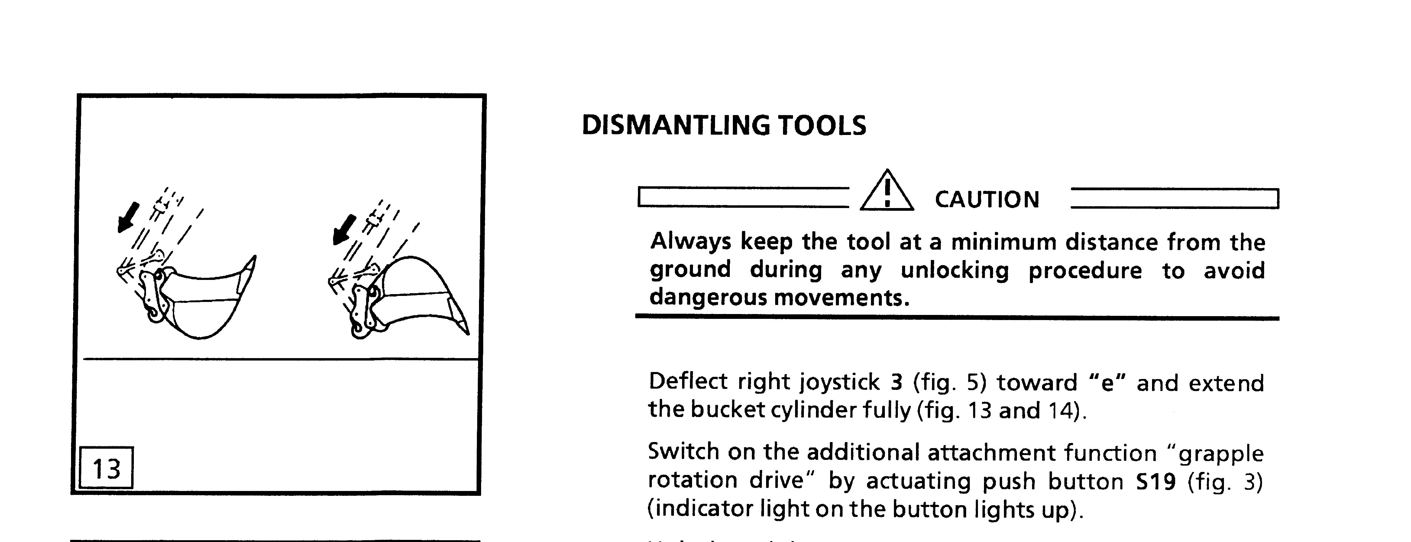
Opening the quick change coupler: Move the equipment so that the tool is lying on the ground, with the bucket cylinder fully extended.
Press touch S19,
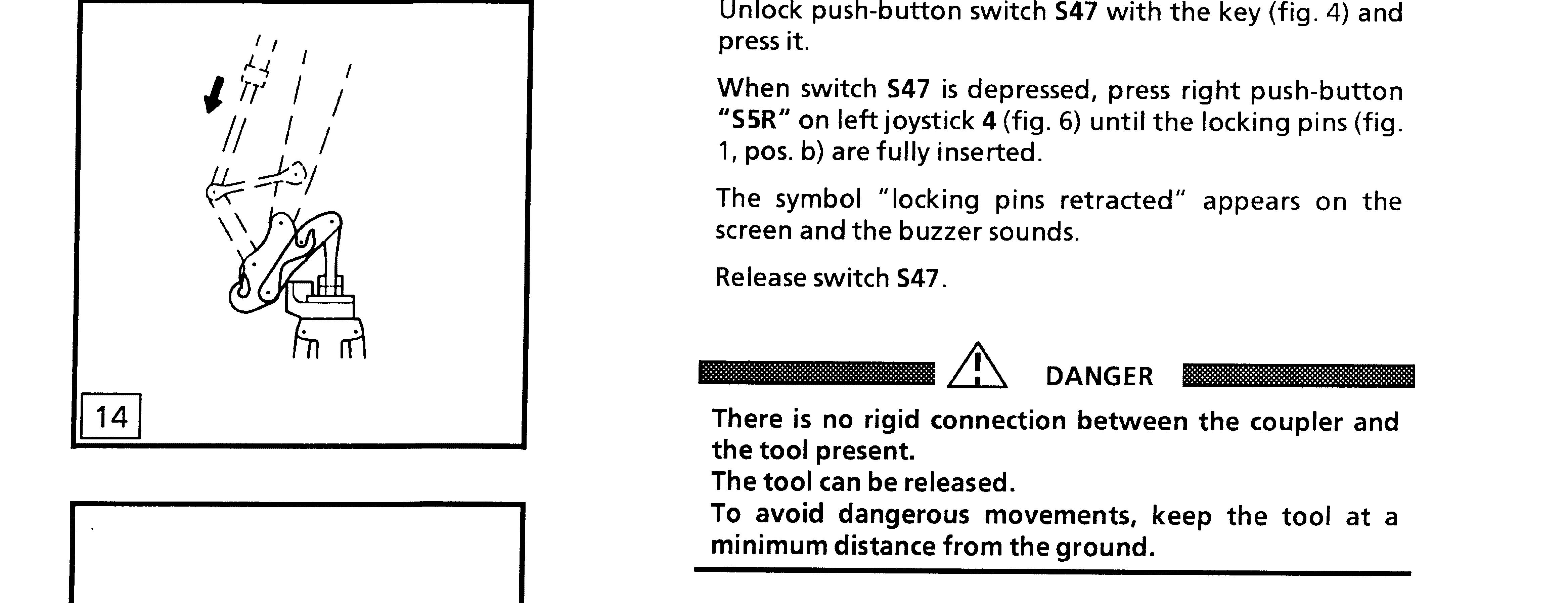
Depress the push button switch S47 (or turn the key switch S47 into position 1 (to the right), and push down the key).
Keep switch S47 depressed, press right push button S5R. The
Simultaneously :
The symbol "Locking pins retr
The buzzer in the cab must sound...............................................
Release the key and turn the switch S47 back to position 0.
Closing the quick change coupler:
Depress the push button switch S47 (or turn the key switch S47 into position 1 (to the right), and press the key).
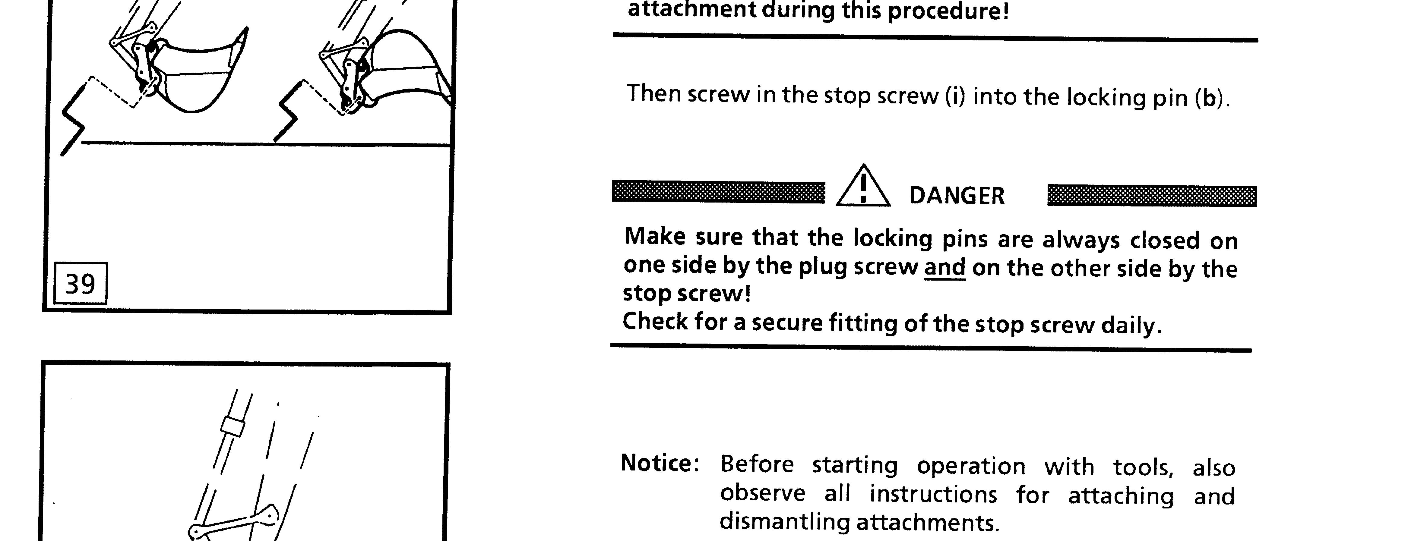
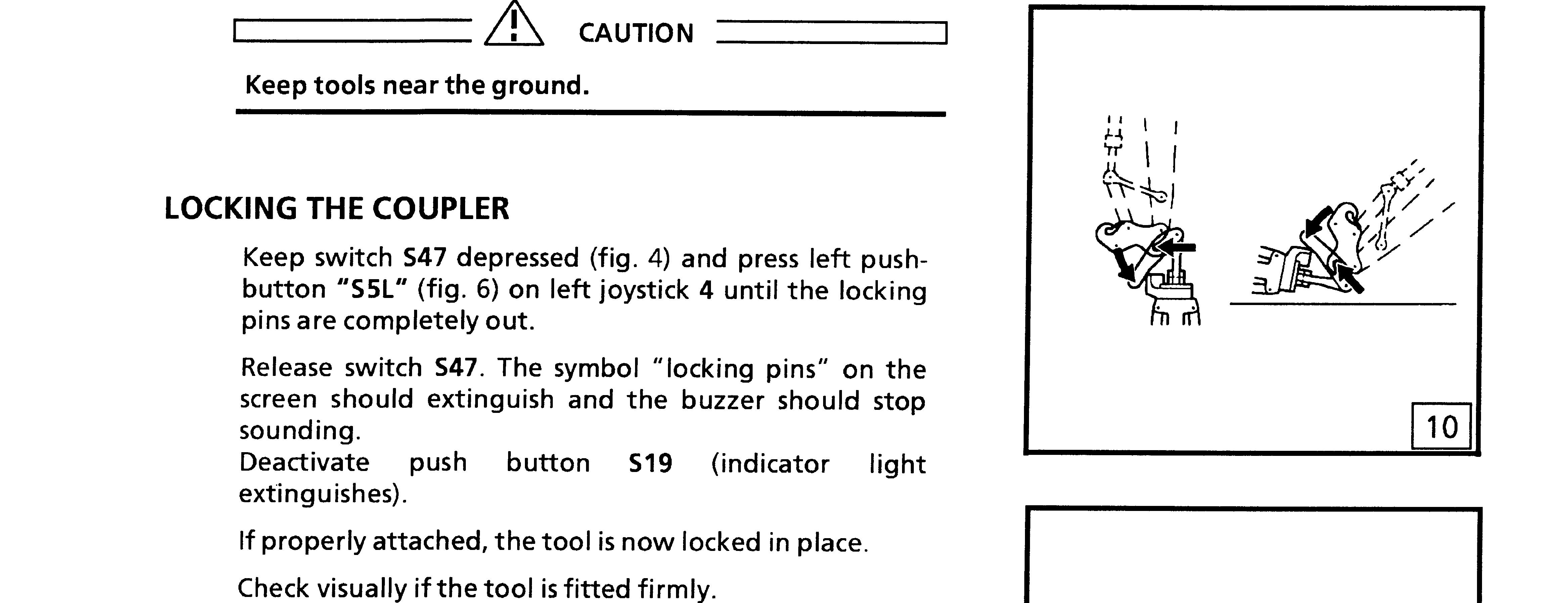
Keep switch S47 depressed, press left button S5L. The quick change coupler locking pins must come out................................
When the locking pins are fully out : Symbol "Locking pins retracted" must light off at the display......
Press touch S19,
Stop the Diesel engine
Daily visual check out
Daily, after above described function verification, control if locking pins a are in fully extended position, that means the tool's attachment bore holes must be flush with locking pins.......
Check also the good condition of the hydraulic hoses b and of the electrical supply bundle between end of stick and quick
Check that the safety latches c on the load hooks are in good working order...........
Lubrication of locking pins.
Once a week, give some stroke of grease into each of 4 lube nipples d located in the area of the locking pins .........................
Screen filters inside supply hoses
Every 1000 operating hours, check out and clean the screen filters mounted inside the fittings between the hoses b and the hydraulic cylinder of the quick change coupler.............................