18 minute read
Lubrication passage


Fig. 134-On Modei L260, rockshaft feedback linkage is adjusted at turnbuckie on link (L).
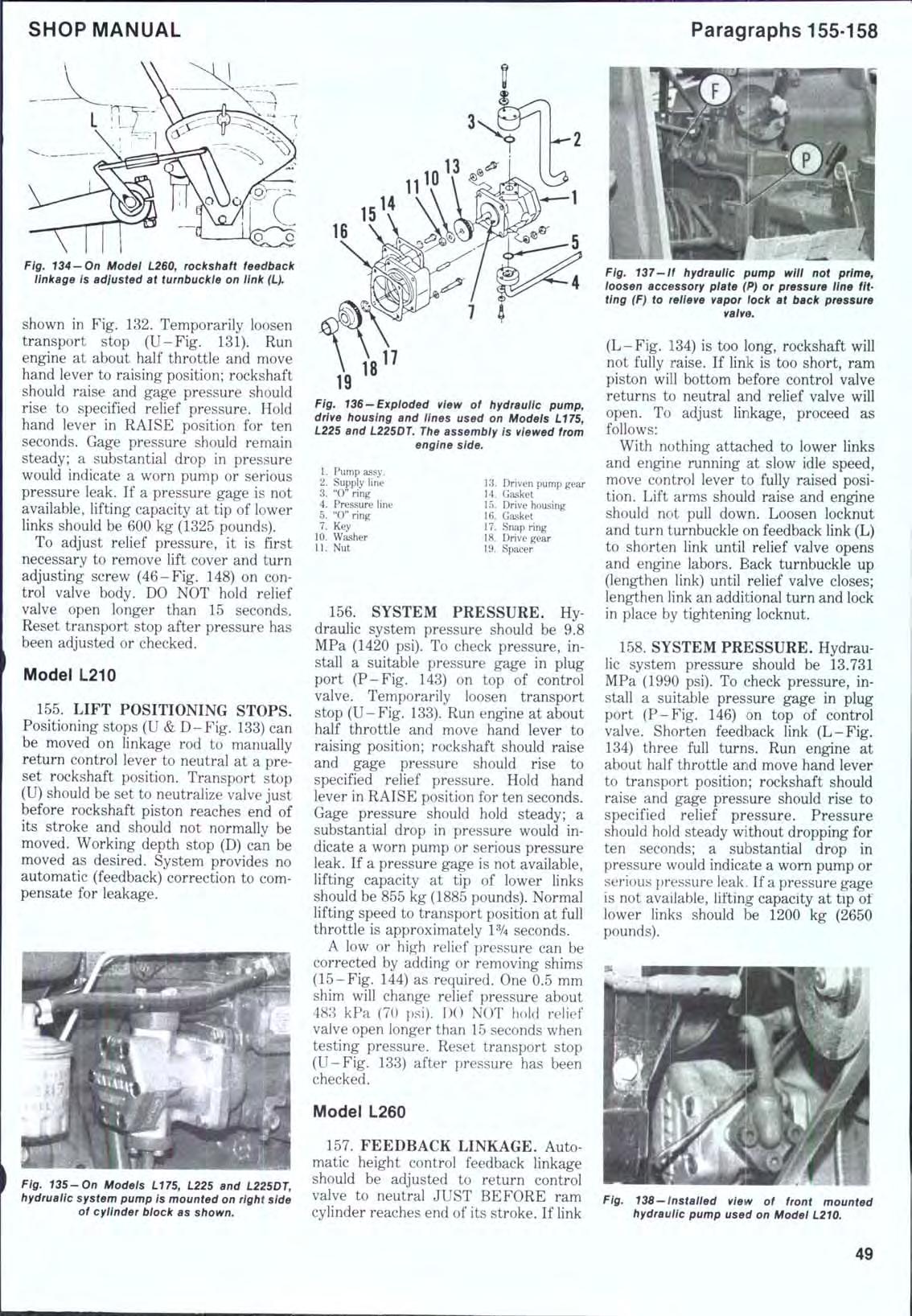
shown in Fig. 132. Temporarily loosen transport stop (U-Fig. 131). Run engine at about half throttle and move hand lever to raising position; rockshaft should raise and gage pressure should rise to specified relief pressure. Hold hand lever in RAISE position for ten seconds. Gage pressure should remain steady; a substantial drop in pressure would indicate a worn pump or serious pressure leak. If a pressure gage is not available, lifting capacity at tip of lower links should be 600 kg (1325 pounds).
To adjust relief pressure, it is first necessary to remove lift cover and turn adjusting screw (46-Fig. 148) on control valve body. DO NOT hold relief valve open longer than 15 seconds. Reset transport stop after pressure has been adjusted or checked.
Model L210
155. LIFT POSITIONING STOPS. Positioning stops (U & D-Fig. 133) can be moved on linkage rod to manually return control lever to neutral at a preset rockshaft position. Transport stop (U) should be set to neutralize valve just before rockshaft piston reaches end of its stroke and should not normally be moved. Working depth stop (D) can be moved as desired. System provides no automatic (feedback) correction to compensate for leakage.
Fig. 135-On Modeis L175, L225 and L225DT, hydruaiic system pump is mounted on right side of cylinder biock as shown. 16
Fig. 136-Expioded view of hydrauiic pump, drive housing and Hnes used on Modeis L775, L22S and L225DT. The assembly is viewed from engine side.
1. Pump assy. 2. Supply line 3. "C'ring 4. Pressure line 5. "0" ring 7. Key 10. Washer 11. Nut 13. Driven pump gear 14. Gasket 15. Drive housing 16. Gasket 17. Snap ring 18. Drive gear 19. Spacer
156. SYSTEM PRESSURE. Hydraulic system pressure should be 9.8 MPa (1420 psi). To check pressure, install a suitable pressure gage in plug port (P-Fig. 143) on top of control valve. Temporarily loosen transport stop (U-Fig. 133). Run engine at about half throttle and move hand lever to raising position; rockshaft should raise and gage pressure should rise to specified relief pressure. Hold hand lever in RAISE position for ten seconds. Gage pressure should hold steady; a substantial drop in pressure would indicate a worn pump or serious pressure leak. If a pressure gage is not available, lifting capacity at tip of lower links should be 855 kg (1885 pounds). Normal lifting speed to transport position at full throttle is approximately 1% seconds.
A low or high relief pressure can be corrected by adding or removing shims (15-Fig. 144) as required. One 0.5 mm shim will change relief pressure about 483 kPa (70 psi). DO NOT hold relief valve open longer than 15 seconds when testing pressure. Reset transport stop (U-Fig. 133) after pressure has been checked.
Model L260
157. FEEDBACK LINKAGE. Auto matic height control feedback linkage should be adjusted to return control valve to neutral JUST BEFORE ram cylinder reaches end of its stroke. If link
Fig. 137-if hydrauiic pump wiii not prime, ioosen accessory plate (P} or pressure line fitting (F} to relieve vapor lock at back pressure valve.
(L-Fig. 134) is too long, rockshaft will not fully raise. If link is too short, ram piston will bottom before control valve returns to neutral and relief valve will open. To adjust linkage, proceed as follows:
With nothing attached to lower links and engine running at slow idle speed, move control lever to fully raised position. Lift arms should raise and engine should not pull down. Loosen locknut and turn turnbuckie on feedback link (L) to shorten link until relief valve opens and engine labors. Back turnbuckie up (lengthen link) until relief valve closes; lengthen link an additional turn and lock in place by tightening locknut.
158. SYSTEM PRESSURE. Hydraulic system pressure should be 13.731 MPa (1990 psi). To check pressure, install a suitable pressure gage in plug port (P-Fig. 146) on top of control valve. Shorten feedback link (L-Fig. 134) three full turns. Run engine at about half throttle and move hand lever to transport position; rockshaft should raise and gage pressure should rise to specified relief pressure. Pressure should hold steady without dropping for ten seconds; a substantial drop in pressure would indicate a worn pump or serious pressure leak. If a pressure gage is not available, lifting capacity at tip ot lower links should be 1200 kg (2650 pounds).
Fig. 138-instailed view of front mounted hydrauiic pump used on Modei L210.
Fig. 139-Exploded view of hydraulic pump, iines and coupling used on Model L210,
1. Pump assy. 2. Supply line 3. "0* ring 4. Pressure line 5. "0" ring 6. Drive joint
A low or high relief pressure can be corrected by adding or removing shims in relief valve (4-Fig. 146). One 1 nim (0.040 inch) shim will change relief pressure approximately 2346 kPa (340 psi). DO NOT hold relief valve open longer than 15 seconds. Reset feedback link after relief pressure has been checked.
PUMP
Models L175-L225-L225DT
159. TESTING. Gear-type hydraulic system pump is mounted on right side of engine and gear driven from rear of injection pump camshaft as shown in Fig. 135. Specified pump delivery is 14.06 L/min (3.7 gpm) at 2700 engine rpm. Pump parts are not serviced and disassembly is not recommended.
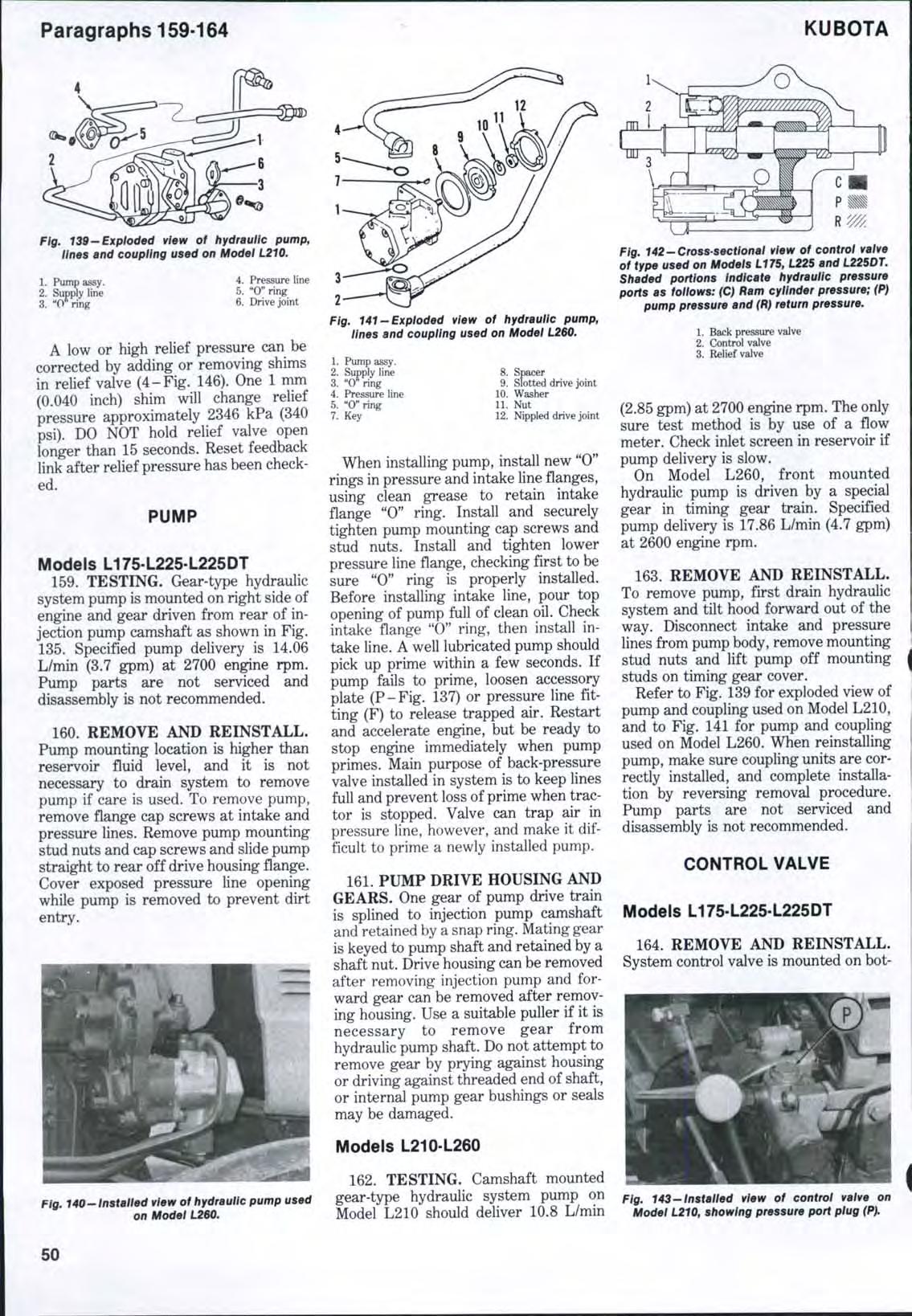
160. REMOVE AND REINSTALL. Pump mounting location is higher than reservoir fluid level, and it is not necessary to drain system to remove pump if care is used. To remove pump, remove flange cap screws at intake and pressure lines. Remove pump mounting stud nuts and cap screws and slide pump straight to rear off drive housing flange. Cover exposed pressure line opening while pump is removed to prevent dirt entry.
Fig. 140-Installed view of hydrauiic pump used on Modet L260. Fig. 141-Exploded view of hydraulic pump, tines and coupling used on Model L260,
1. Pump assy. 2. Supply line 3. "O" ring 4. Pressure line 5. "0" ring 7. Key 8. Spacer 9. Slotted drive joint 10. Washer 11. Nut 12. Nippled drive joint
When installing pump, install new "0" rings in pressure and intake line flanges, using clean grease to retain intake flange "0" ring. Install and securely tighten pump mounting cap screws and stud nuts. Install and tighten lower pressure line flange, checking first to be sure "0" ring is properly installed. Before installing intake line, pour top opening of pump full of clean oil. Check intake flange "0" ring, then install intake line. A well lubricated pump should pick up prime within a few seconds. If pump fails to prime, loosen accessory plate (P-Fig. 137) or pressure line fitting (F) to release trapped air. Restart and accelerate engine, but be ready to stop engine immediately when pump primes. Main purpose of back-pressure valve installed in system is to keep lines full and prevent loss of prime when tractor is stopped. Valve can trap air in pressure line, however, and make it difficult to prime a newly installed pump.
161. PUMP DRIVE HOUSING AND GEARS. One gear of pump drive train is splined to injection pump camshaft and retained by a snap ring. Mating gear is keyed to pump shaft and retained by a shaft nut. Drive housing can be removed after removing injection pump and forward gear can be removed after removing housing. Use a suitable puller if it is necessary to remove gear from hydraulic pump shaft. Do not attempt to remove gear by prying against housing or driving against threaded end of shaft, or internal pump gear bushings or seals may be damaged.
Models L210-L260
162. TESTING. Camshaft mounted gear-type hydraulic system pump on Model L210 should deliver 10.8 L/min
Fig, 142-Cross-sectlonat vtew of control vatve of type used on Models L175, L225 and L225DT. Shaded porttons Indicate hydraultc pressure ports as follows: (C) Ram cylinder pressure; (P) pump pressure and (R) return pressure.
1. Back pressure valve 2. Control valve 3. Relief valve
(2.85 gpm) at 2700 engine rpm. The only sure test method is by use of a flow meter. Check inlet screen in reservoir if pump delivery is slow.
On Model L260, front mounted hydraulic pump is driven by a special gear in timing gear train. Specified pump delivery is 17.86 L/min (4.7 gpm) at 2600 engine rpm.
163. REMOVE AND REINSTALL. To remove pump, first drain hydraulic system and tilt hood forward out of the way. Disconnect intake and pressure lines from pump body, remove mounting stud nuts and lift pump off mounting studs on timing gear cover.
Refer to Fig. 139 for exploded view of pump and coupling used on Model L210, and to Fig. 141 for pump and coupling used on Model L260. When reinstalling pump, make sure coupling units are correctly installed, and complete installation by reversing removal procedure. Pump parts are not serviced and disassembly is not recommended.
CONTROL VALVE
Models L175-L225-L225DT
164. REMOVE AND REINSTALL. System control valve is mounted on bot-
Ftg. 143-Installed view of control valve on Modet LZ10, showtng pressure port ptug (P).
33
32
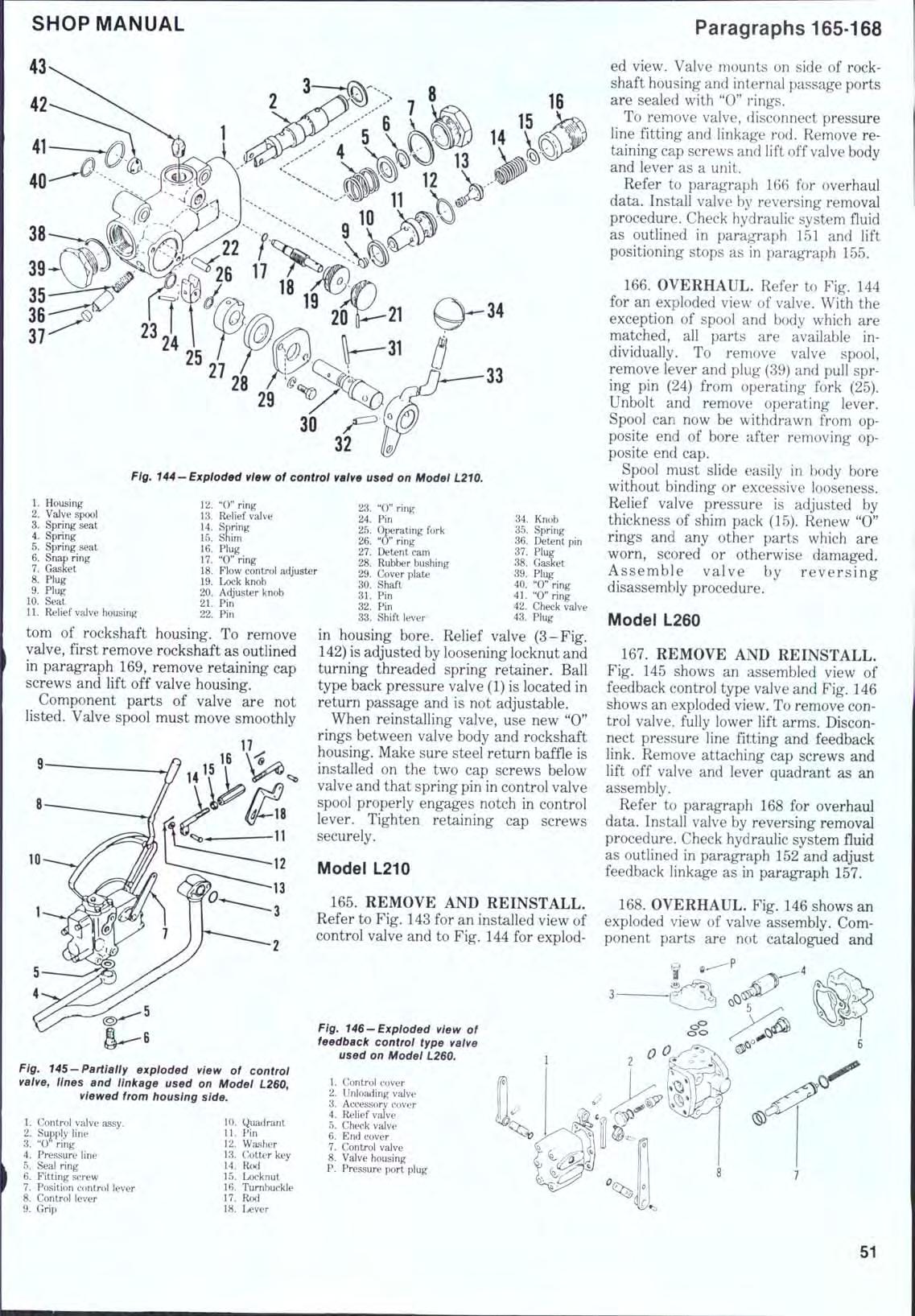
F/0. 144-Exploded view of control valve used on Model L210.
1. Housing 2. Valve spool 3. Spring seat 4. Spring 5. Spring seat 6. Snap ring 7. Gasket 8. Plug 9. Plug 10. Seat 11. Relief valve housing 12. "0" ring 13. Relief valve 14. Spring 15. Shim 16. Plug 17. "0" ring 18. Flow control adjuster 19. Lock knob 20. Adjuster knob 21. Pin 22. Pin 23. "0" ring 24. Pin 25. Ctoerating fork 26. "0" ring 27. Detent cam 28. Rubber bushing 29. Cover plate 30. Shaft 31. Pin 32. Pin 33. Shift lever 34. Knob 35. Spring 36. Detent pin 37. Plug 38. Gasket 39. Plug 40. "0" ring 41. "0" ring 42. Check valve 43. Plug
torn of rockshaft housing. To remove valve, first remove rockshaft as outlined in paragraph 169, remove retaining cap screws and lift off valve housing.
Component parts of valve are not listed. Valve spool must move smoothly in housing bore. Relief valve (3-Fig. 142) is adjusted by loosening locknut and turning threaded spring retainer. Ball type back pressure valve (1) is located in return passage and is not adjustable.
When reinstalling valve, use new "0" rings between valve body and rockshaft housing. Make sure steel return baffle is installed on the two cap screws below valve and that spring pin in control valve spool properly engages notch in control lever. Tighten retaining cap screws securely.
Model L210
165, REMOVE AND REINSTALL. Refer to Fig, 143 for an installed view of control valve and to Fig. 144 for exploded view. Valve mounts on side of rockshaft housing and internal passage ports are sealed with "0" rings.
To remove valve, disconnect pressure line fitting and linkage rod. Remove retaining cap screws and lift off valve body and lever as a unit.
Refer to paragraph 166 for overhaul data. Install valve b}^ reversing removal procedure. Check hydraulic system fluid as outlined in paraj^aph 151 and lift positioning stops as in paragraph 155.
166, OVERHAUL. Refer to Fig. 144 for an exploded view of valve. With the exception of spool and body which are matched, all parts are available individually . To remove valve spool, remove lever and plug (39) and pull spring pin (24) from operating fork (25), Unbolt and remove operating lever. Spool can now be withdrawn from opposite end of bore after removing opposite end cap.
Spool must slide easily in body bore without binding or excessive looseness. Relief valve pressure is adjusted by thickness of shim pack (15), Renew "0" rings and any other parts which are worn, scored or otherwise damaged. Assemble valve by reversing disassembly procedure.
Model L260
167, REMOVE AND REINSTALL. Fig, 145 shows an assembled view of feedback control type valve and Fig. 146 shows an exploded view. To remove control valve, fully lower lift arms. Disconnect pressure line fitting and feedback link. Remove attaching cap screws and lift off valve and lever quadrant as an assembly.
Refer to paragraph 168 for overhaul data. Install valve by reversing removal procedure. Check hydraulic system fluid as outlined in paragraph 152 and adjust feedback linkage as in paragraph 157.
168, OVERHAUL. Fig, 146 shows an exploded view of valve assembly. Component parts are not catalogued and
Fig. 145-Partiaiiy exploded view of control vaive, iines and iinkage used on Modei L260, viewed from housing side.
1. Control valve assy. 2. Supply line 3. "0" ring 4. Pressure line 5. Seal ring 6. Fitting screw 7. Position control lever 8. Control lever 9. Grip 10. Quadrant U. Pin 12. Washer 13. Cotter key 14. Rod 15. Locknut 16. Tumbuckle 17. Rod 18. Lever
Fig. 146-Expioded view of feedback controi type vaive used on Modei L260.
1. Control cover 2. Unloading valve 3. Accessory cover 4. Relief valve 5. Check valve 6. End cover 7. Control vaive 8. Valve housing P. Pressure port plug
Fig. 147— Rear view of Model LI75 tractor showing rockshaft linkage correctly instailed.
7 e^ J
disassembly except for cleaning or inspection is not advised. Control valve (7) is spring loaded in lowering position and is moved toward neutral or raise position by feedback linkage in control cover (1). Adjustments are fixed. Unloading valve (2) is open to by pass pump flow to reservoir except in raising position, when it is seated by fluid admitted to larger area behind valve. Check valve (5) opens to permit fluid flow to ram cylinder and seats to block return flow at all other times. Pressure relief valve (4) is shim adjusted. Tighten plug in end of relief valve (4) to a torque of 20-27 N-m (15-20 ft.-lbs.). Tighten relief valve (4), check valve (5) and unloading valve (2) into housing to a torque of 61-68 N • m (45-50 ft.-lbs.). Tighten cap retaining screws to a torque of 20 N*m (15 ft.-lbs.).
ROCKSHAFT HOUSING Model L175L225-L225DT
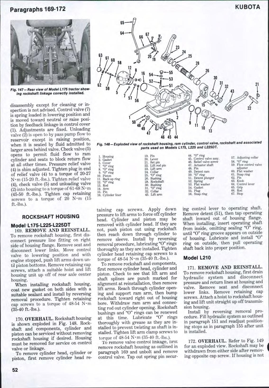
169. REMOVE AND REINSTALL. To remove rockshaft housing, first disconnect pressure line fitting on right side of housing flange. Remove seat and disconnect lower links. Move control valve to lowering position and with engine stopped, push lift arms down until piston bottoms. Remove retaining cap screws, attach a suitable hoist and lift housing unit up off of rear axle center housing.
When installing rockshaft housing, coat new gasket on both sides with a suitable sealant and install by reversing removal procedure. Tighten retaining cap screws to a torque of 48-54 N*m (35-40 ft.-lbs.). 170. OVERHAUL. Rockshaft housing is shown exploded in Fig. 148. Rockshaft and components, cylinder and piston can be serviced without removing rockshaft housing if desired. Housing must be removed for service on control valve or linkage.
To remove cylinder head, cylinder or piston, flrst remove cylinder head re-
47
48 45 44 13
Fig 148-Exploded view of rockshaft housing, ram cylinder, control valve, rockshaft and associated parts used on Modeis L17S, L225 and L225DT.
1. Housing 2. Gasket 5. Cover 7. *'O''ring 8. "0" ring 9. "O" ring 10. Piston U. Back-up ring 12. "O"ring 13. Rod 14. Arm 15. Pin 16. Cylinder liner 19. Pin 20. Lever 21. Set pin 22. Lift rod pin 23. Lift arm 24. Collar 25. "O''ring 26. Bushing 28. Rockshaft 30. Bushing 31. "0" ring 32. Collar 43. Lift arm 44. "O"ring 45. Control valve assy. 46. Relief valve screw 47. Actuator shaft 48. Pin 49. Detent cam 50. "O"ring 51. Detent plunger 52. Spring 53. Flat washer 54. Gasket 55. Plug 56. Snap ring 57. Adjusting collar 58. "0" ring 59. Flow control valve adjuster 60. Flat washer 61. Snap ring 62. Pin 63. Knob 64. Control lever 65. Grip 66. Rod 67. Stop
taining cap screws. Apply down pressure to lift arms to force off cylinder head. Cylinder and piston may be removed with cylinder head. If they are not, push piston out using rockshaft then reach down through cylinder to remove sleeve. Install by reversing removal procedure, lubricating "0" rings thoroughly as they are installed. Tighten cylinder head retaining cap screws to a torque of 48-54 N-m (35-40 ft.-lbs.).
To remove rockshaft and components, first remove cylinder head, cylinder and piston. Check to see that lift arm and shaft splines are punch marked for alignment at reinstallation, then remove lift arms. Reach through cylinder opening and support ram arm, then bump rockshaft toward right out of housing bore. Withdraw ram arm and connecting rod out cylinder opening. Rockshaft bushings and "0" rings can be renewed at this time. Lubricate "0" rings thoroughly with grease as they are installed to prevent twisting as shaft is installed. Tighten lift arm clamp screws to torque of 48-54 N-m (35-40 ft.-lbs.).
To remove valve control Imkage, rirsi; remove rockshaft housing as outlined in paragraph 169 and unbolt and remove control valve. Tap out spring pin securing control lever to operating shaft. Remove detent (51), then tap operating shaft inward out of housing flange. When installing, insert operating shaft from inside, omitting sealing "0" ring, until "0" ring groove appears on outside of housing. Lubricate and install "0" ring on outside, then pull operating shaft back into proper position.
Model L210
171. REMOVE AND REINSTALL. To remove rockshaft housing, first drain hydraulic system and disconnect pressure and return lines at housing and valve. Remove seat and disconnect lower links. Remove retaining cap screws. Attach a hoist to rockshaft housing and lift unit straight up off transmission housing.
Install by reversing removal procedure. Fill hydraulic system as outlined in paragraph 151 and readjust positioning stops as in paragraph 155 after unit is installed.
172. OVERHAUL. Refer to Fig. 149 for an exploded view. Rockshaft may be withdrawn from either side after removing opposite cap screw. If housing is not
1 3 2 13
Fig. 149-Exploded view of rockshaft housing, rockshaft and ram cyiinder used on Model L210.
1. Housing 2. Rear cover 3. Gasket 4. Gasket 5. Front cover 6. "0" ring 7. "0" ring 8. Back-up ring 9. Piston 10. Rod 11. Pin 12. Snap ring 13. Cap screw 14. L(x;kwasher 15. Flat washer 16. Spacer 17. Lift arm 18. Collar 19. Bushing 20. Rockshaft 21. "0" ring 22. Arm 23. Lift arm
Fig. 151 — Cross-sectional view of intake tube, fiiter and associated paiis used on Modei L260. tf " C rings (R) ieak, filtee (F) is piugged, or tubes or iines are damaged, pump may be noisy or lose prime.
removed for rockshaft overhaul, first remove rear plate and support ram arm as rockshaft is withdrawn. Bushings, spacers and "0" rings will be removed with shaft on side from which shaft is withdrawn. Piston may be pushed out to front after removing cylinder head.
Model L260 21
173. REMOVE AND REINSTALL. To remove rockshaft housing and hydraulic system reservoir, first drain system and disconnect pressure and intake lines leading to pump. Remove seat and disconnect lower links. Remove transmission filler cap and dipstick. Remove cap screws and stud nuts securing rockshaft housing to transmission housing, attach a hoist to housing and lift unit straight up off of transmission housing. Place unit on a clean, flat surface, being careful not to damage oil
pan.
Install by reversing removal procedure. Fill hydraulic system as outlined in paragraph 152.
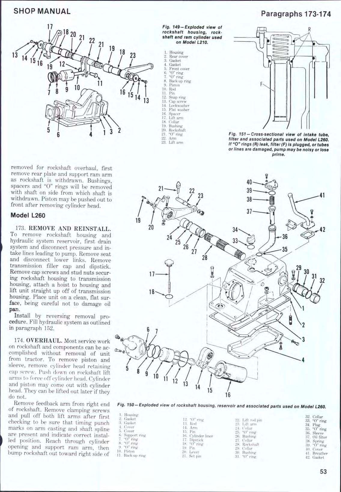
174. OVERHAUL. Most service work on rockshaft and components can be accomplished without removal of unit from tractor. To remove piston and sleeve, remove cylinder head retaining caj) screw. Push (iown on rockshaft lift arms to force off cylinder head. Cylinder and piston may come out with cylinder head. They can be lifted out later if they do not.
Remove feedback arm from right end of rockshaft. Remove clamping screws and pull off both lift arms after first checking to be sure that timing punch marks on arm casting and shaft spline are present and indicate correct installed position. Reach through cylinder opening and support ram arm, then bump rockshaft out toward right side of
Fig. 150-Expioded view of rockshaft housing, reservoir and associated parts used on Modei L260.
1. Housing2. Gasket 'A. Gasket 4. Cover T). Cover B. SupjK)rt ring 7. "0" ring 8. "O" ring 9. "0" ring 10. Piston 11. Back-uf) ring 12. "(T'ring 33. Rwi 14. Arm 15. Pin 16. Cylinder liner 17. Dipstick 18. "0" ring 19. Pin 20. Lever 21. Set pin 22. Lift rod pin 28. Lift arm 24. Collar 25. "0" ring 26. Bushing 27. Collar 28. Rockshaft 29. Collar 30. Bushing 31. "Cring 32. Collar 33. "0" ring 34. Plug 35. "0" ring 36. Sleeve 37. Oil filter 38. Spring 39. "O"ring 40. Cover 4L Breather 42. Gasket
housing. Ram arm and connecting rod can now be withdrawn through cylinder opening. Ram arm splines are also punch marked. Ram arm is installed with centerline 120 degrees from centerline of lift arms.
Pump intake tube elbow must hook forward as shown in Fig. 150. Make sure "0" rings (R-Fig. 151) are in good condition and do not leak. Air leaks will cause pump to be noisy or lose prime.
If oil pan is removed, be careful not to bend or scratch gasket surface. Leaks will cause loss of fluid and contamination of transmission lubricant. Coat oil pan gasket on both sides with a suitable non-hardening sealant and tighten flange screws evenly.
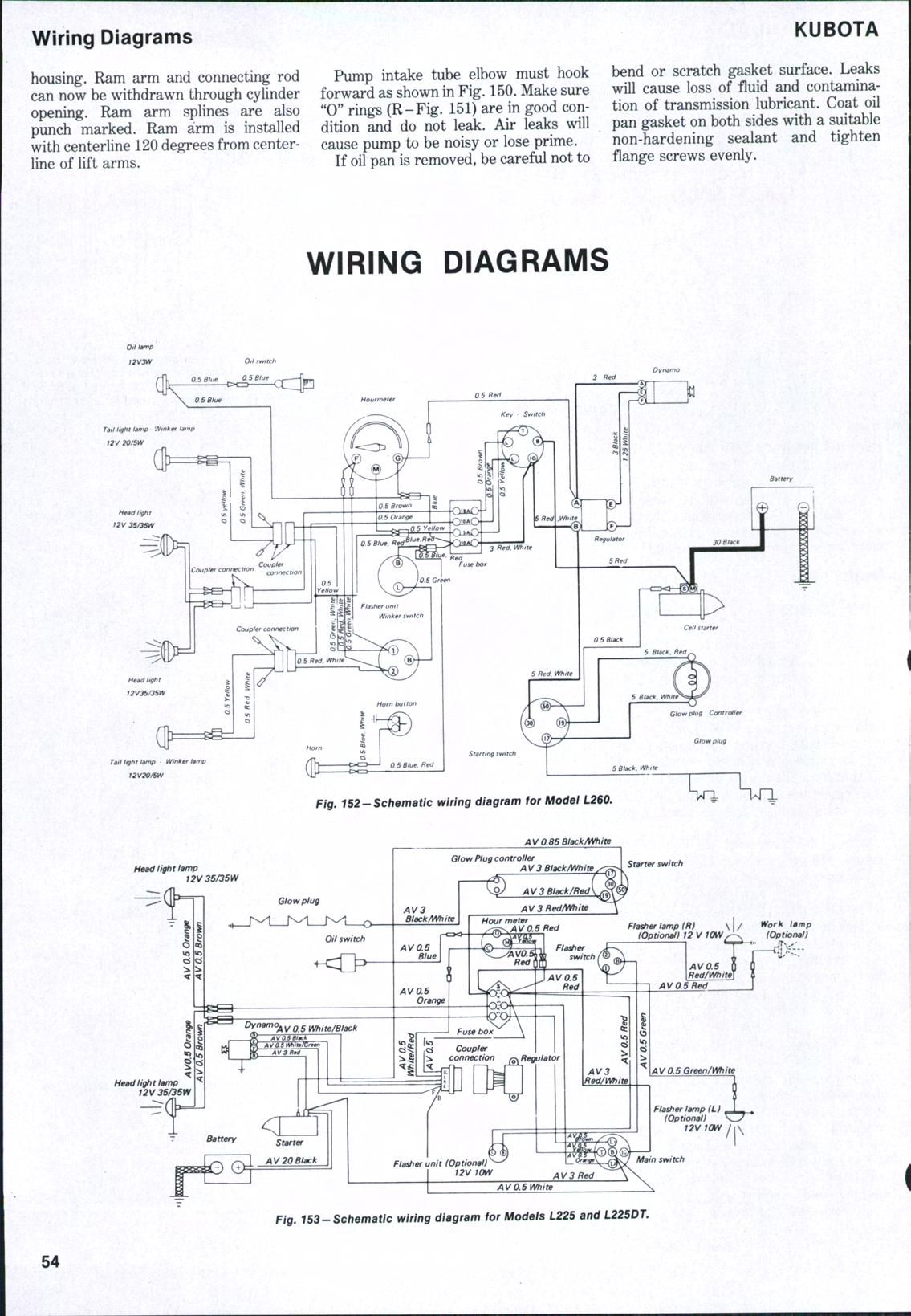
WIRING DIAGRAMS
Tail light lamp 'jVinker tan
)2V 2Q/SW
Tail light lamp • Wmker lamp