2 minute read
End plate


11 12 13 15
clean unit. Examine internal clutch surface of housing and outer surface of floating splined hub for ridging or scoring. Renew sprag unit, hub and housing if damage is found. Engaging action will be reversed if sprag unit is reversed. Check for correct rotation as previously outlined when unit is reassembled.
38 37 36 40 41 42
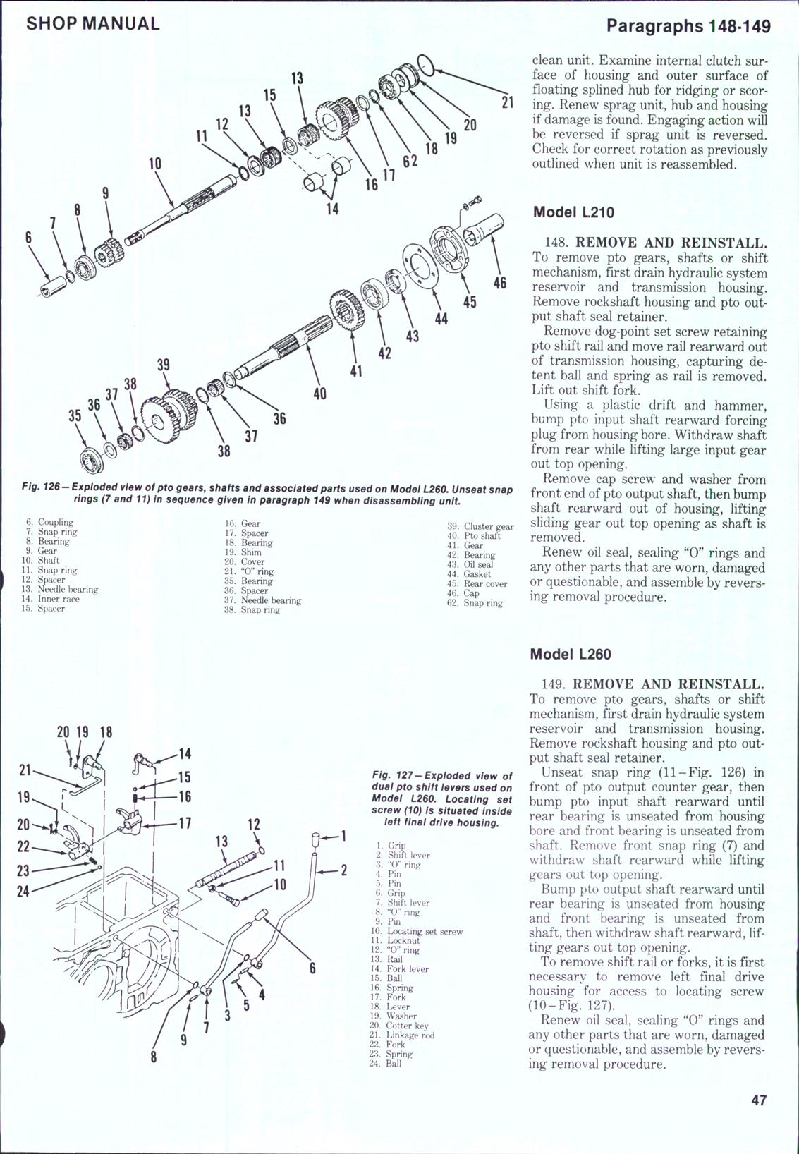
Fig. 12$" Exploded view of pto gears, shafts and associated parts used on Model L260. Unseat snap rings (7 and 11) In sequence given in paragraph 149 when disassembilng unit.
6. Coupling 7. Snap tnng 8. Bearing 9. Gear 10. Shaft 11. Snap ring 12. Spacer 13. Needle bearing 14. Inner race 15. Spacer 16. Gear 17. Spacer 18. Bearing 19. Shim 20. Cover 21. "C'ring 35. Bearing 36. Spacer 37. Needle bearing 38. Snap ring 39. Cluster gear 40. Pto shaft 41. Gear 42. Bearing 43. Oil seal 44. Gasket 45. Rear cover 46. Cap 62. Snap ring
Model L210
148. REMOVE AND REINSTALL. To remove pto gears, shafts or shift mechanism, first drain hydraulic system reservoir and transmission housing. Remove rockshaft housing and pto output shaft seal retainer.
Remove dog-point set screw retaining pto shift rail and move rail rearward out of transmission housing, capturing detent ball and spring as rail is removed. Lift out shift fork.
Using a plastic drift and hammer, bump pto input shaft rearward forcing plug from housing bore. Withdraw shaft from rear while lifting large input gear out top opening.
Remove cap screw and washer from front end of pto output shaft, then bump shaft rearward out of housing, lifting sliding gear out top opening as shaft is removed.
Renew oil seal, sealing "0" rings and any other parts that are worn, damaged or questionable, and assemble by reversing removal procedure.
20 19 IB
Fig. 127-Expioded view of duai pto shift ievers used on Modei L2$0. Locating set screw (10) is situated inside ieft finai drive housing.
1. Grip 2. Shift lever 3. "0" ring 4. Pin 5. Pin 6. Grip 7. Shift lever 8. "0" ring 9. Pin 10. Locating set screw 11. Locknut 12. "0" ring 13. Rail 14. Fork lever 15. Ball 16. Spring 17. Fork 18. Lever 19. Washer 20. Cotter key 21. Linkage rcxi 22. Fork 23. Spring 24. Ball
Model L260
149. REMOVE AND REINSTALL. To remove pto gears, shafts or shift mechanism, first drain hydraulic system reservoir and transmission housing. Remove rockshaft housing and pto output shaft seal retainer.
Unseat snap ring (11-Fig, 126) in front of pto output counter gear, then bump pto input shaft rearward until rear bearing is unseated from housing bore and front bearing is unseated from shaft. Remove front snap ring (7) and withdraw shaft rearward while lifting gears out top opening.
Bump pto output shaft rearward until rear bearing is unseated from housing and front bearing is unseated from shaft, then withdraw shaft rearward, lifting gears out top opening.
To remove shift rail or forks, it is first necessary to remove left final drive housing for access to locating screw (10-Fig. 127).
Renew oil seal, sealing "0" rings and any other parts that are worn, damaged or questionable, and assemble by reversing removal procedure.