2 minute read
Gasket


FLUID AND FILTERS
Models L175 L225L225DT
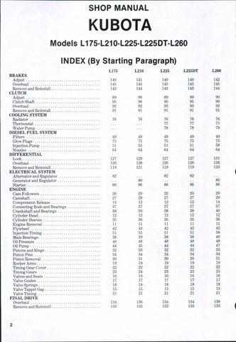
150. Transmission and differential lubricant serves as hydraulic fluid and transmission housing is fluid reservoir. Reservoir capacity is 22.04 liters (5.8 gallons) on Models L175 and L225 and 22 liters (5.75 gallons) on Model L225DT and recommended fluid is SAE 80 transmission and hydraulic fluid. An intake strainer is located beneath access plate (F-Fig. 128) on left side of final drive housing directly opposite pump intake line and a fluid level plug (L) is located on left side of transmission housing. Transmission and hydraulic fluid should be changed every 300 hours and
Fig. 128-On Modeis L17S, L225 and L225DT, inlet oil filter is located beneath access piate (F). Fluid Ievei plug is shown at (L).
inlet strainer removed and cleaned at each fluid change.
Model L210
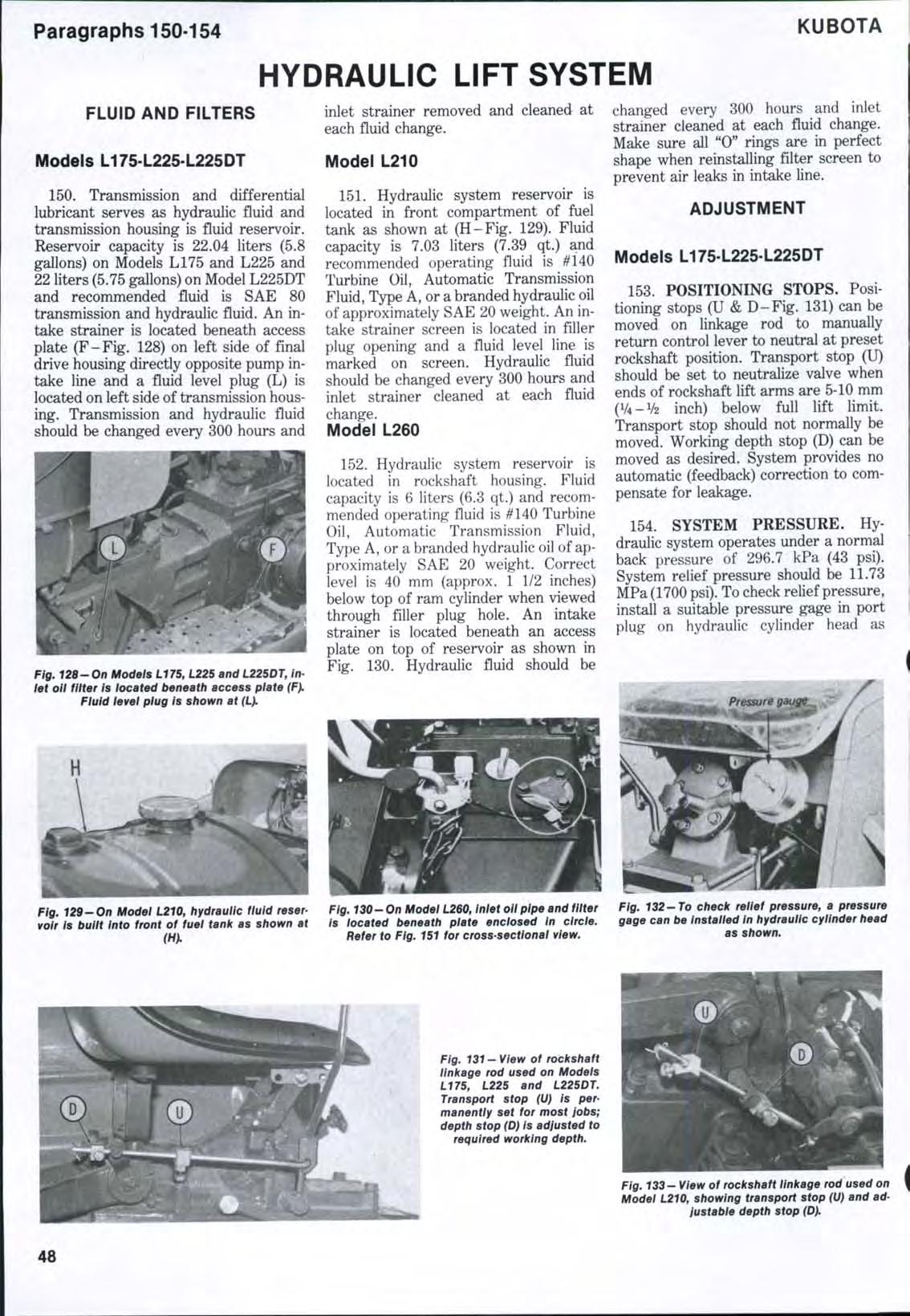
151. Hydraulic system reservoir is located in front compartment of fuel tank as shown at (H-Fig. 129). Fluid capacity is 7.03 liters (7.39 qt.) and recommended operating fluid is #140 Turbine Oil, Automatic Transmission Fluid, Type A, or a branded hydraulic oil of approximately SAE 20 weight. An intake strainer screen is located in filler plug opening and a fluid level line is marked on screen. Hydraulic fluid should be changed every 300 hours and inlet strainer cleaned at each fluid change.
Model L260
152. Hydraulic system reservoir is located in rockshaft housing. Fluid capacity is 6 liters (6.3 qt.) and recommended operating fluid is #140 Turbine Oil, Automatic Transmission Fluid, Type A, or a branded hydraulic oil of approximately SAE 20 weight. Correct level is 40 mm (approx. 1 1/2 inches) below top of ram cylinder when viewed through filler plug hole. An intake strainer is located beneath an access plate on top of reservoir as shown in Fig. 130. Hydraulic fluid should be changed every 300 hours and inlet strainer cleaned at each fluid change. Make sure all "0" rings are in perfect shape when reinstalling filter screen to prevent air leaks in intake line.
ADJUSTMENT
Models L175 L225 L225DT
153. POSITIONING STOPS. Positioning stops (U & D-Fig. 131) can be moved on linkage rod to manually return control lever to neutral at preset rockshaft position. Transport stop (U) should be set to neutralize valve when ends of rockshaft lift arms are 5-10 mm (V4-V2 inch) below full lift limit. Transport stop should not normally be moved. Working depth stop (D) can be moved as desired. System provides no automatic (feedback) correction to compensate for leakage.
154. SYSTEM PRESSURE. Hydraulic system operates under a normal back pressure of 296.7 kPa (43 psi). System relief pressure should be 11.73 MPa (1700 psi). To check relief pressure, install a suitable pressure gage in port plug on hydraulic cylinder head as