11 minute read
EXPLANATION OF COMPONENTS OPERATION


Explanation Of Screens
The screen uses a CGC monitor. (CGC: Color Graphic Console)
Opening Screen
After the starting switch is turned ON, it takes approx. 20 seconds for the condition of the machine to be displayed. The opening screen is displayed during this time.
REMARK
● In cold weather, the screen display is slightly delayed, but this does not indicate any failure.
● VHMS: Vehicle Health Monitoring System
Hello!
Welcome to VHMS system
The system in now building up
Please wait a moment
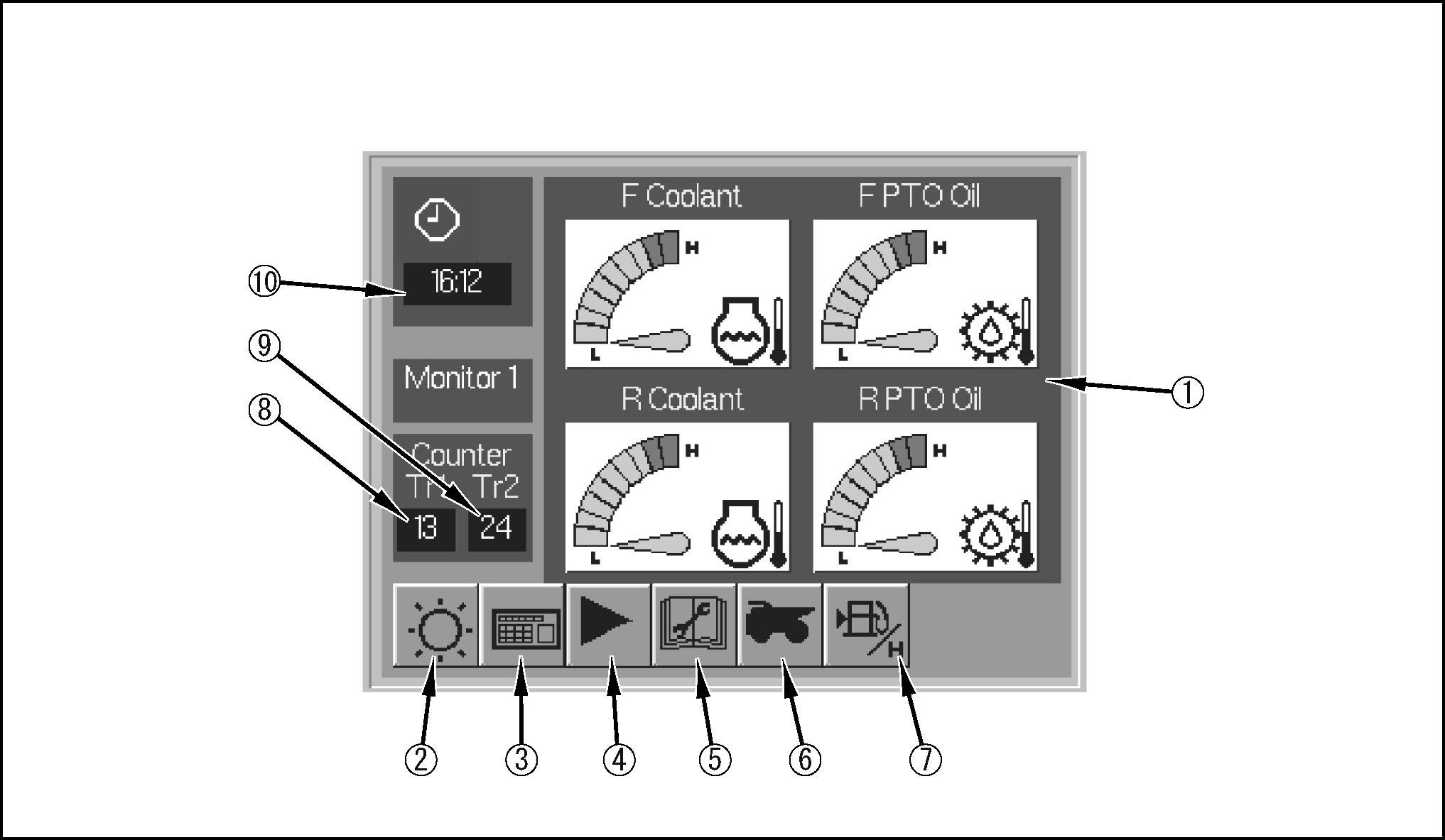
Normal Screen
The screen automatically switches to this screen approx. 5 seconds after the starting switch is turned on. It displays the oil temperatures, water temperatures, and oil pressures on the meters.
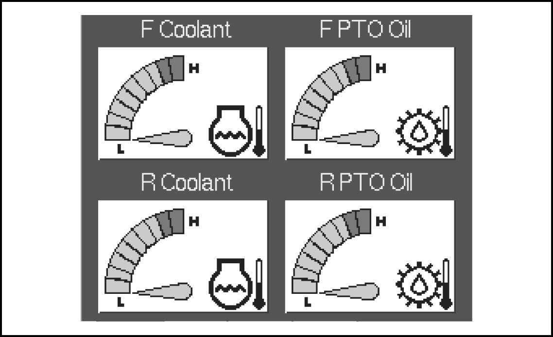
Meter display
This meter display (1) portion displays the water temperatures, oil temperatures, and pressures. The content of the display can be changed by pressing display selector button (4).
Brightness control screen display button
This button (2) switches the brightness display screen. For details of the method of adj usting the brightness, see “BRIGHTNESS CONTROL SCREEN (PAGE 3-27)”.
Setting screen display button
This button (3) switches to the setting screen.
Display screen display button
This button (4) switches the display to the next screen. Each time it is pressed, the display screen switches in the following cycle: monitor 1 ➝ monitor 2 ➝ monitor 3 ➝ monitor 1.
Monitor 1:Front engine water temperature, rear engine water temperature, front PTO oil temperature, rear PTO oil temperature


Monitor 2:Front engine oil temperature, rear engine oil temperature, front engine oil pressure, rear engine oil pressure
Monitor 3:Front PTO oil temperature, rear PTO oil temperature, hydraulic oil temperature
Maintenance screen display button

This button (5) switches to the maintenance screen. The color of the letters on this button (5) changes as follows according to the number of hours remaining to the next maintenance.
30 hours remaining:Yellow 0 hours remaining:Red
Truck counter button


This button (6) is used to switch to the screen for inputting the user ID in order to clear the counter and for resetting the counter for the number of trucks loaded.
Fuel consumption measurement screen selector button
This button (7) is used to switch to the fuel consumption measurement screen. On the fuel consumption measurement screen, it is possible to set the hourly fuel consumption.
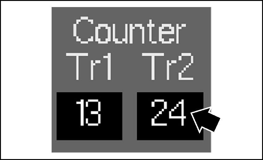
Truck counter display 1
On this counter display (8), the count for the number of trucks loaded is displayed.
The counter is advanced by pressing truck counter switch (A) at the top of the left control lever on the side at the front of the machine. Each time truck counter switch (A) is pressed, truck counter lamp (C) on the instrument panel on the right side of the operator’s seat flashes once.
Truck counter display 2
On this counter display (9), the count for the number of trucks loaded is displayed. The counter is advanced by pressing truck counter switch (B) at the top of the left work equipment control lever on the side at the rear of the machine. Each time truck counter switch (B) is pressed, truck counter lamp (C) on the instrument panel on the right side of the operator's seat flashes once.
REMARK
If the switch is pressed to match by mistake during operation of the hydraulic excavator, do not press the switch for the next count to compensate the number on the counter. Truck counter switches (A) and (B) differ in the size of the truck being loaded, so please use these switches when it is necessary to differentiate.
Time display
This meter display (10) displays the preset time.
Brightness Control Screen
This screen is used to adjust the brightness and contrast of the machine management monitor screen.
(1) Brightness control screen(3) Brightness control button
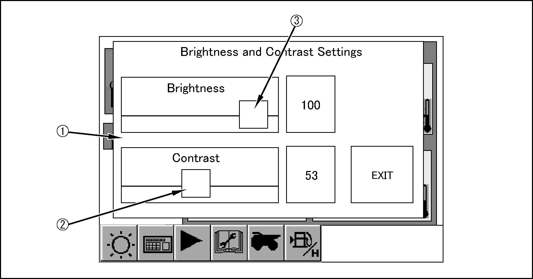
(2) Contrast control button
Brightness control screen
When selector button for the brightness control screen (1) on the normal screen is pressed, the sub-screen is displayed on top of the normal screen.
Contrast control button
This button (2) is used to adjust the contrast of the screen. Touch button (2) on the screen and slide it to the desired position.
Brightness control button
This button (3) is used to adjust the brightness of the screen. Touch button (3) on the screen and slide it to the desired position.
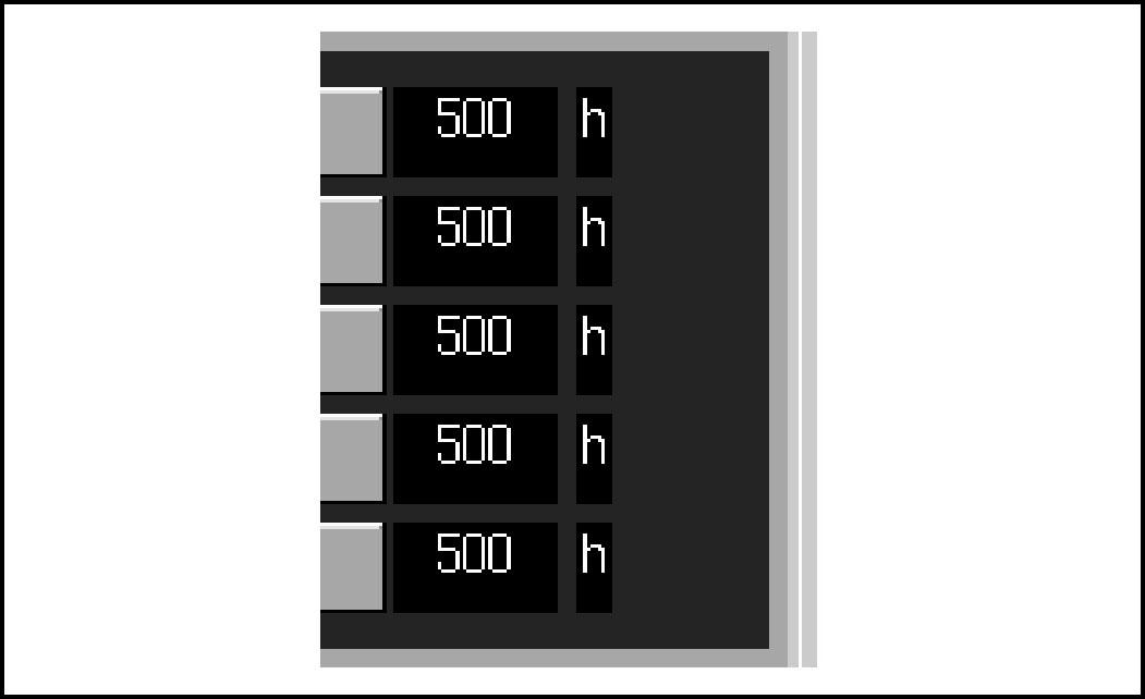
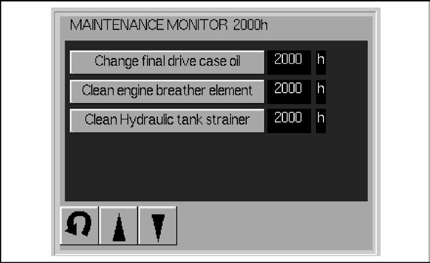
Maintenance Screen
This maintenance screen displays the number of hours remaining until the next maintenance for each maintenance item.

The color of the letters on this screen and the color of the letters on the selector buttons on the maintenance screen of the normal screen change as follows according to the number of hours remaining to the next maintenance.
30 hours remaining:Yellow
0 hours remaining:Red
Standard maintenance interval display
This display portion (1) displays the standard maintenance interval.

Maintenance item display
This display portion (2) displays the maintenance items.
Remaining time display

This display (3) displays the time remaining until the next maintenance.
Maintenance item selector button (previous)
This button (4) switches the maintenance items display to the previous display. Each time the button is pressed, the display changes (E) ➝ (D) ➝ (C) ➝ (B) ➝ (A).

Maintenance item selector button (next)
This button (5) switches the maintenance items that are displayed.
Each time the button is pressed, the display changes (A) ➝ (B) ➝ (C) ➝ (D) ➝ (E).
(A): Maintenance items for every 250 hours
● Replace hydraulic tank breather filter element
(B): Maintenance items for every 500 hours

● Change engine oil
● Replace engine oil filter cartridge
● Replace hydraulic filter element
● Replace drain filter cartridge
● Replace fuel filter
(C): Maintenance items for every 1000 hours

● Change oil in swing machinery case
● Change oil in PTO case
● Replace corrosion resistor cartridge
(D): Maintenance items for every 2000 hours
● Change oil in final drive case
● Wash engine breather element
● Wash hydraulic tank strainer
(E): Maintenance items for every 5000 hours

● Change oil in hydraulic tank

Normal screen selector button

This button (6) switches to the normal screen.
Resetting maintenance interval
After replacing the oil or filter for each maintenance item, reset the time remaining to maintenance as follows to the original maintenance interval.


1.Press maintenance item screen (1) to specify the item on the maintenance screen to be reset. The maintenance item screen (1) will flash.
2.When maintenance item screen (1) flashes, press maintenance item screen (1) once more.
3.The confirmation screen in the diagram on the right is displayed. Press the (YES) but ton. If the (NO) button is pressed, the time remaining to maintenance stays as it is.
4.Using the compensation screen in the diagram on the right, time deletion screen (2) and maintenance interval screen (3) are displayed.
5.Press the maintenance item to be reset on the maintenance interval screen (3). The display for time deletion screen (2) goes out and only maintenance interval screen (3) is displayed.
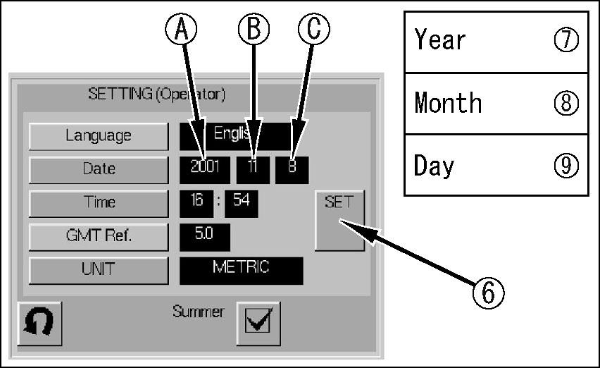
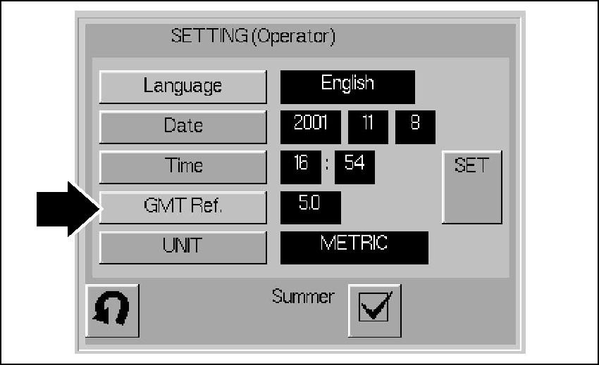
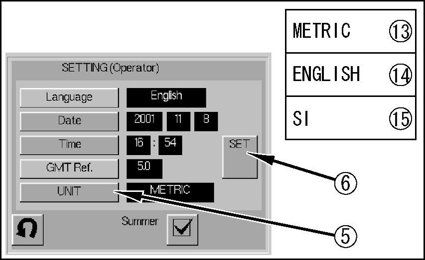
Setting Screen
This screen is used to input the language, date, time, and display unit.
(1) Language selector button(10) Sub-screen 10-key input button


(2) Date setting button(11) Time input sub-screen button
Language selector button
This button (1) is used to selector the language used for the management monitor display.
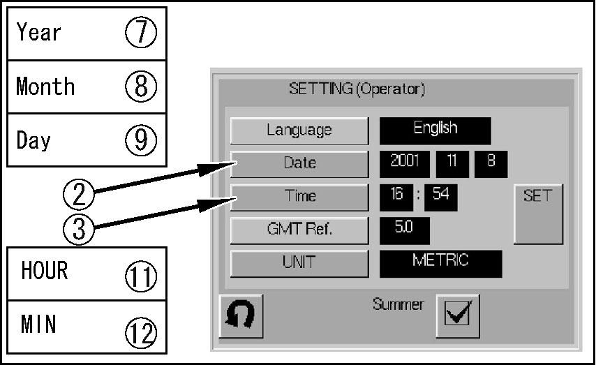
Date setting button
This button (2) is used to input the date. The procedure is as follows.
1.When this button (2) is pressed, date input sub-screens button (7), (8), and (9) are displayed. When this happens, date displays (A), (B), and (C) flash.
2.Press (YEAR) on date input sub-screen (7).
3.When Step 2. the 10-key screen shown in the diagram on the right is displayed.
4. Input the numerals for the year, then press Enter button (D). The 10-key display goes out.
● If the wrong number is input, press Clear button (E), then input the numbers again.
● To stop the operation before completing it, press (Exit) button (F).
5.When Step 4. is completed, date display screen (A) lights up and screens (B) and (C) flash.
6.Press (Month) on date input sub-screen button (8). The 10-key screen is displayed.
7.Input the numerals for the month, then press Enter button (D). The 10-key display goes out.
8.When Step 7. is completed, date display screens (A) and (B) light up and screen (C) flashes.
9.Press Day on date input sub-screen (9). The 10-key screen is displayed.
10.Input the numerals for the day, then press Enter button (D). The 10-key display goes out.
11.When Step 10. is completed, date display screens (A), (B), and (C) light up.
12.Press setting button (6). Date input sub-screens button (7), (8), and (9) go out to inform the operator that the date setting process has been completed.

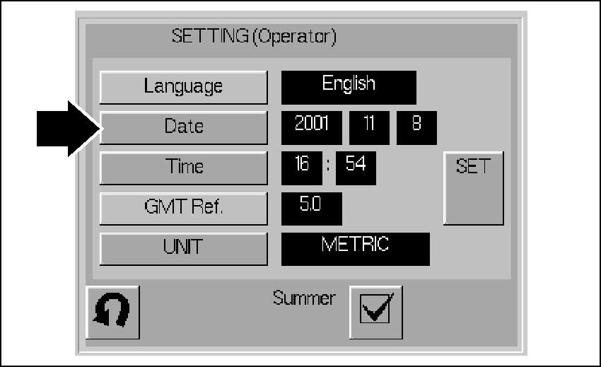
Time setting button
This button (3) is used to input the time. The procedure is as follows.
1.When this button (3) is pressed, date input sub-screens buttons (11) and (12) are displayed. When this happens, time displays (A) and (B) flash.
2.Press (HOUR) on time input sub-screen button (11).
3.The 10-key screen shown in the diagram on the right is displayed.
4.Input the numerals for the hour, then press Enter button (D). The 10-key display goes out.
● If any mistake is made in inputting the numbers, press Clear button (E), then input the numbers again.
● To stop the operation before completing it, press Exit button (F).
5.When Step 4. is completed, time display screen (A) lights up and screen (B) flashes.
6.Press (MIN) on time input sub-screen button (12). The 10-key screen is displayed.


7.Input the numerals for the minute, then press Enter button (D). The 10-key display goes out.
8.When Step 7. is completed, time display screens (A) and (B) light up.
9.Press setting button (6). Time input sub-screens buttons (11) and (12) go out to inform the operator that the time setting process has been completed.
Time difference selector button
This button (4) is used to select the time difference.
The operator cannot change the time difference. If it is necessary to change the time difference, please ask your Komatsu distributor to carry out the change.
Display unit setting button
This button (5) is used to select the units used on the CGC monitor display.
The operation is as follows.
1.When button (5) is pressed, display unit input subscreens buttons (13), (14), and (15), are displayed.
2.Press the necessary units on display unit input subscreens (13), (14), and (15). The symbol for the unit is displayed on unit display (A).
3.Press setting button (6). Display unit input sub-screens buttons (13), (14), and (15) go out to inform the operator that the unit setting process has been completed.
Unit symbols
● SI:The SI units are displayed. (When the language is set to Japanese, only the SI units are displayed.)

● METRIC:The metric units are displayed.
● ENGLISH:Yards, pounds, etc. are displayed.
Item setting button
This button (6) is pressed as the final confirmation when setting the language, date, time, time difference, and unit display, and completes the setting operation.
Date input sub-screen button
● When date setting button (2) is pressed, input sub-screen buttons (7), (8), and (9) are displayed, and the date input operation can be carried out.

● When time setting button (3) is pressed, time input subscreen buttons (11) and (12) are displayed, and the time input operation can be carried out. In addition, if input buttons (7), (8), (9), (11), or (12) are pressed, the 10-key screen (10) is displayed and numerals can be input.

Sub-screen 10-key input button
● This display (10) is displayed when setting the date or time. Numerals can be input up to ten digits.
● When Enter button (D) is pressed, the operation is completed. When the operation is completed, 10-key display (10) goes out, the screen returns to the setting screen, and the input data is displayed.
● If any mistake is made in inputting the numbers, press Clear button (E), then input the numbers again. All the numerals are deleted.
● To stop the operation before completing it, press (Exit) button (F). The screen returns to the setting screen.
Display unit input sub-screen button
When display unit setting button (5) is pressed, display unit input sub-screens buttons (13), (14), and (15) are displayed, and the unit input setting operation can be carried out.
● When the language is set to Japanese, only SI units (15) can be set.
When setting button (6) is pressed, display unit input subscreens buttons (13), (14), and (15) go out.
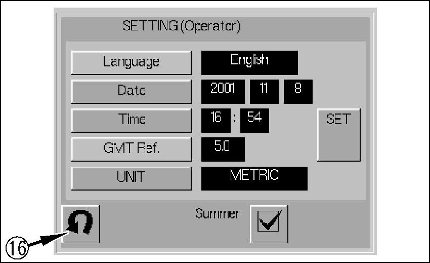
Normal screen selector button
When this button (16) is pressed, the screen switches to the “NORMAL SCREEN (PAGE 3-21)”.
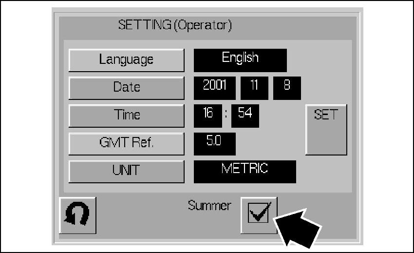
Summer time setting button
Press this button (17) to input Summer Time (Daylight Saving Time).
REMARK
Summer time (daylight saving time) is a system used in more than 70 countries around the world to make the most effective use of daylight by advancing the clock 1 hour in summer when the time of sunrise is early.
The procedure is as follows.
1.When this button (17) is pressed, time input sub-screens (11) and (12) are displayed. When this happens, date displays (A) and (B) flash.
2.Press HOUR on time input sub-screen (11).
3.The 10-key screen shown in the diagram on the right is displayed.
4.Input the numerals for summer time, then press enter button (D). The 10-key display goes out.
● If any mistake is made in inputting the numbers, press clear button (E), then input the numbers again.
● To stop the operation before completing it, press exit button (F).
5.When Step 4. is completed, time display screen (A) lights up and screen (B) flashes.
6.Press (MIN) on time input sub-screen (12). The 10-key screen is displayed.
7.Input the numerals for the minute, then press enter button (D). The 10-key display goes out.
8.When Step 7. is completed, time display screens (A) and (B) light up.
9.Press setting button (6). Time input sub-screens (11) and (12) on the setting screen go out to inform the operator that the time setting process has been completed.
Fuel Consumption Measurement Screen
This screen displays the fuel consumption during the desired period from the start of operations (starting engine) to the completion of operations (stopping engine).
(1) Fuel consumption measurement start date display(4) Start/stop button
(2) Fuel consumption measurement stop date display(5) Time display
(3) f uel consumption display(6) Normal screen selector button
Fuel consumption measurement start/stop date display
To set the starting date for measuring the fuel consumption, press the fuel consumption measurement screen selector button on the normal screen. When the fuel consumption measurement screen is displayed, it is automatically displayed in display portion (1).
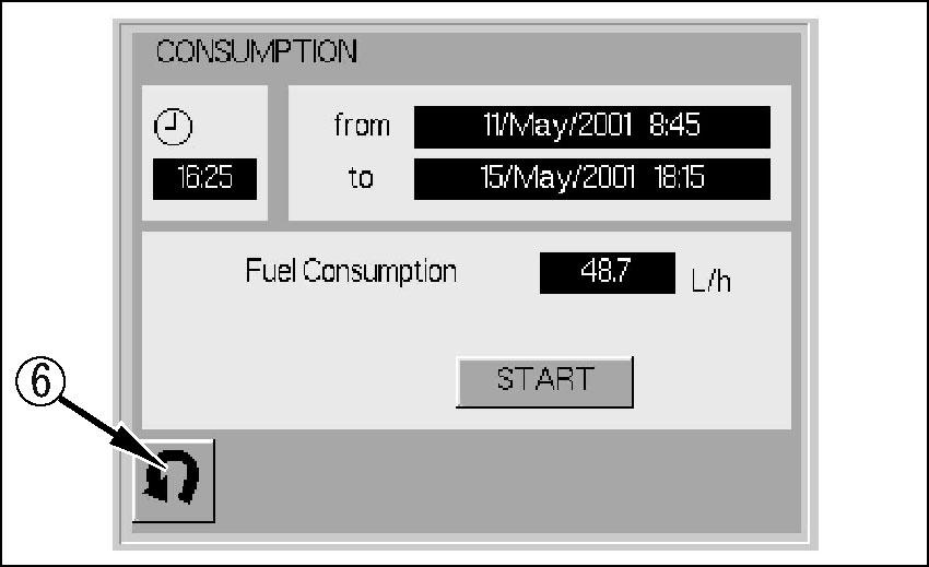
Display portion (2) is displayed when start/stop button (STOP) button (4) is pressed to stop measurement of the fuel consumption.
Fuel display
The previous value of the fuel consumption measurement that was displayed on the fuel consumption measurement screen is displayed on this display (3). Press the start/stop (START) button, and the present fuel consumption value is displayed at the same time as the fuel consumption measurement starts.

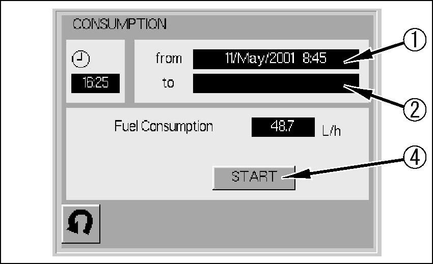
● The fuel consumption value on display (3) is the average value for the are the fuel consumption (L/h) from the time when the start/stop (START) button was pressed to the point where the start/stop (STOP) button is pressed again.

Start/stop button
This button (4) has two types of functions: fuel consumption measurement button and stop button.
● Before measurement of the fuel consumption is started, (START) is displayed on button (4).


● If button (4) is pressed when the display is START, measurement of the fuel consumption starts. When button (4) is pressed, (STOP) is displayed on the button.
● When stopping measurement of the fuel consumption, press button (4) when the display is (STOP). When button (4) is pressed, (START) is displayed on the button.
Time display
The present time is displayed on this meter display (6). If it is necessary to correct the time, see “SETTING SCREEN (PAGE 3-21)” for details.
Normal screen selector button
When this button (6) is pressed, the screen switches to the “NORMAL SCREEN (PAGE 3-21)”.
Truck Counter Screen
This screen is used to input the user ID and to reset the number of trucks loaded after it has been cleared.


User ID input button
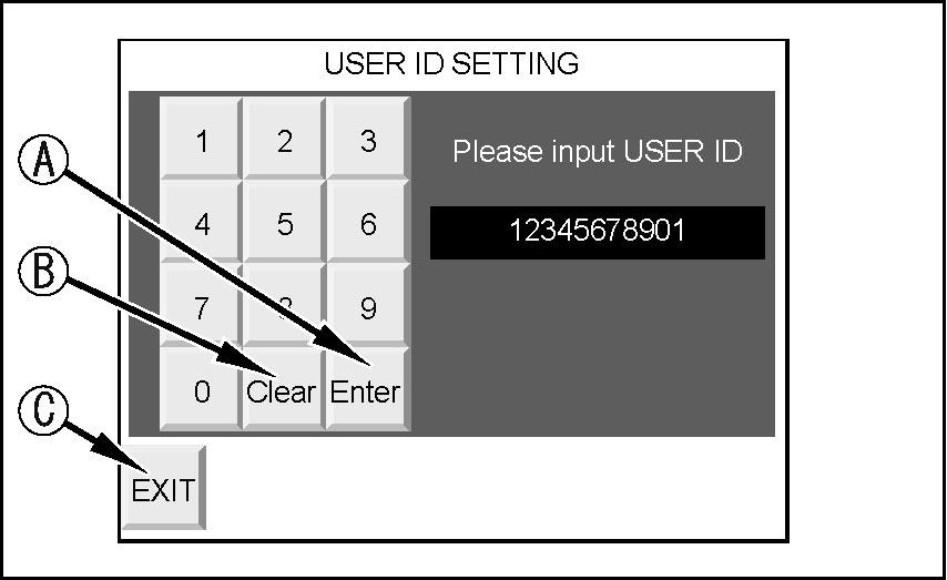
This button (1) is used to input the user ID. The procedure is as follows.
1.When this button (1) is pressed, the 10-key screen in the diagram on the right is displayed.
2.After inputting the desired ID number, press Enter button (A). The 10-key screen goes out and the new ID number is displayed.
● The ID number can be input to a maximum of ten digits, so input the number of digits desired.
● If any mistake is made in inputting the numbers, press Clear button (B), then input the numbers again.
● To stop the operation before completing it, press (Exit) button (C).
Remark
● If the cleared number of trucks loaded for each hydraulic excavator operator is to be displayed in memory, input the user ID number.
● If it is desired to count the total number of trucks loaded, regardless of changes in shift of the hydraulic excavator operator, leave the ID number at the default setting and continue the count.
