3 minute read
Display assembly


Description
14.1-inch, WXGA BrightView display assembly for use only with computer models with wireless LAN capability (includes wireless antenna transceivers and cables)
14.1-inch, WXGA BrightView display assembly for use only with computer models without wireless LAN capability
Spare part number
448328-001
448327-001
Before removing the display assembly, follow these steps: 1. Shut down the computer. If you are unsure whether the computer is off or in Hibernation, turn the computer on, and then shut it down through the operating system. 2. Disconnect all external devices connected to the computer. 3. Disconnect the power from the computer by first unplugging the power cord from the AC outlet and then unplugging the AC adapter from the computer. 4. Remove the battery (see Battery on page 31). 5. Remove the memory/WLAN module compartment cover (see Memory module on page 35) and disconnect the wireless antenna cables from the WLAN module (see WLAN module on page 37). 6. Remove the following components: a. Switch cover (see Switch cover on page 41) b. Keyboard (see Keyboard on page 43) Remove the display assembly: 1. Close the computer and turn it upside down, with the rear panel toward you. 2. Remove the two Phillips PM2.0×7.0 screws that secure the display assembly to the computer.
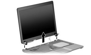
3. Turn the computer display-side up, with the front toward you. 4. Open the computer until the display assembly is in an upright position.
5. Disconnect the display cable connector(1) from the system board and remove the display panel cable (2) from the clips and routing channel built into the top cover. 6. Remove the wireless antenna cables (3) from the clips and routing channel built into the top cover. 7. Remove the two Phillips PM2.0×9.0 screws (4) that secure the display assembly to the computer.
8. Lift the display assembly straight up and remove it.

9. If it is necessary to replace the display bezel or any of the display assembly internal subcomponents, remove the following display bezel screw covers and screws: (1) Four round rubber screw covers on the display bezel top edge. The display bezel screw covers are available in the Display Screw Cover Kit, spare part number 438542-001. All screws used to secure display assembly internal subcomponents are available in the Display Screw Kit, spare part number 438543-001.
(2) Four flat rubber screw covers on the display bezel bottom edge. (3) Eight Phillips PM2.5×6.0 screws.
10. Flex the inside edges of the top side (1), the left and right sides (2) of the display bezel, and the bottom side (3) of the display bezel until the bezel disengages from the display assembly. 11. Remove the display bezel (4). The bezel is available using spare part number 438535-001.
12. If it is necessary to replace the display inverter, remove the Phillips PM2.5×6.0 screw (1) that secures the inverter to the display enclosure. 13. Disconnect the display panel cable (2) and the backlight cable (3) from the inverter.


14. Remove the display inverter (4). The inverter is available using spare part number 448332-001.
15. If it is necessary to replace the display panel, remove the four Phillips PM2.5×6.0 screws (1) that secure the panel to the display enclosure. 16. Remove the display panel (2). The panel is available using spare part number 448333-001.
17. If it is necessary to replace either of the display hinges, remove the four Phillips PM2.0×3.0 screws (1) that secure each hinge to the display panel.

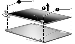
18. Remove the display hinges (2). The hinges are available in the Display Bracket/Hinge Kit, spare part number 448335-001.
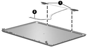
19. If it is necessary to replace the wireless antenna transceivers (1) and cables (2), remove the transceivers and cables from the display enclosure. The wireless antenna transceivers and cables are available in the Wireless Antenna Kit, spare part number 438516-001.
NOTE: The wireless antenna transceivers are attached to the display enclosure by a thin layer of adhesive. It may be necessary to use a flat-bladed tool to pry the transceivers away from the display enclosure.
Reverse this procedure to reassemble and install the display assembly.