4 minute read
not inc Iu de d )


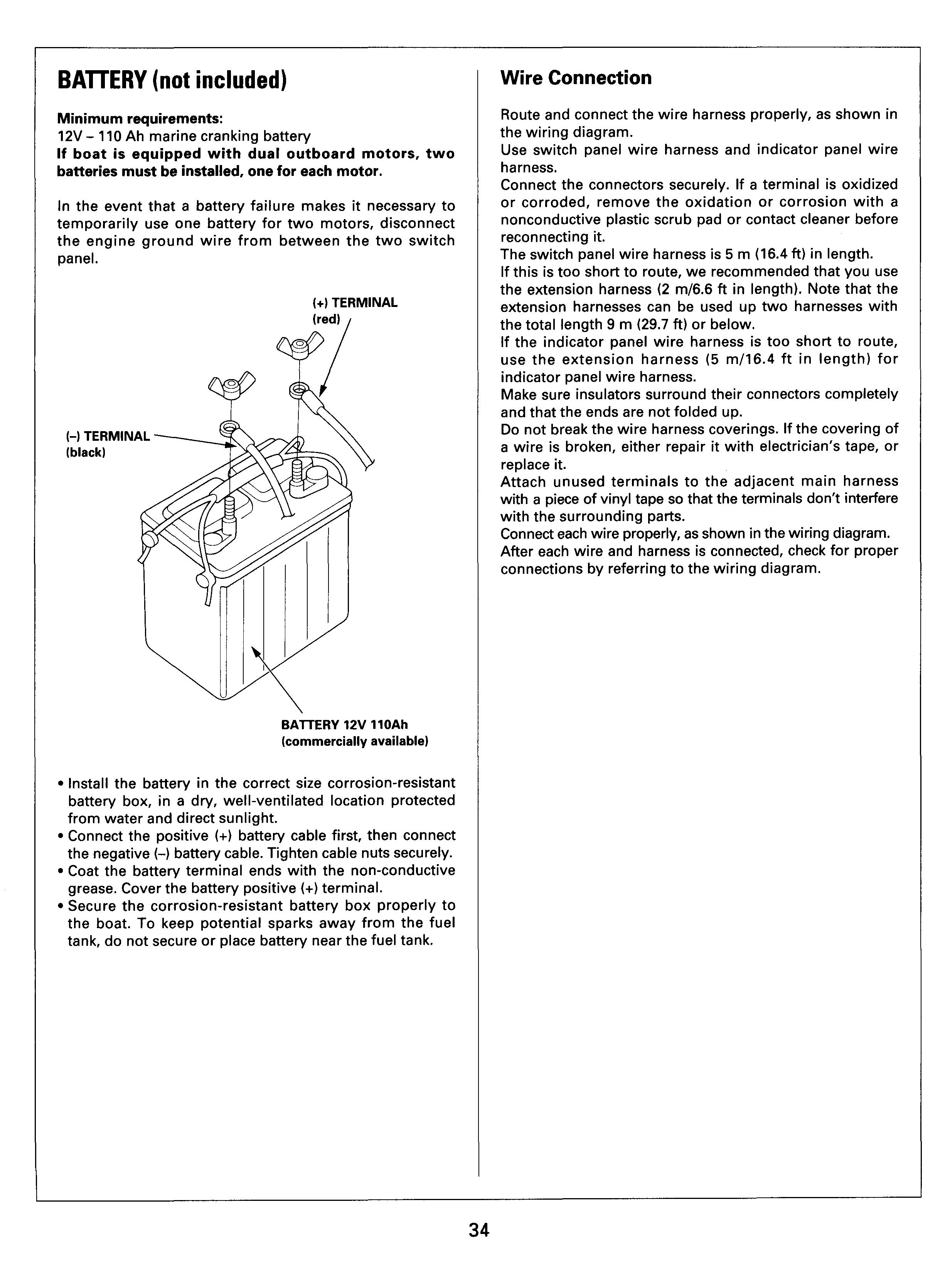
Minimum requirements:
12V - 110 Ah marine cranking battery
If boat is equipped with dual outboard motors, two batteries must be installed, one for each motor.
In the event that a battery failure makes it necessary to temporarily use one battery for two motors, disconnect the engine ground wire from between the two switch panel.
(+) TERMINAL (red) 1
Wire Connection
Route and connect the wire harness properly, as shown in the wiring diagram.
Use switch panel wire harness and indicator panel wire harness.
Connect the connectors securely. If a terminal is oxidized or corroded, remove the oxidation or corrosion with a nonconductive plastic scrub pad or contact cleaner before reconnecting it.
The switch panel wire harness is 5 m (16.4 ft) in length. If this is too short to route, we recommended that you use the extension harness (2 m/6.6 ft in length). Note that the extension harnesses can be used up two harnesses with the total length 9 m (29.7 ft) or below.
If the indicator panel wire harness is too short to route, use the extension harness (5 d16.4 ft in length) for indicator panel wire harness.
Make sure insulators surround their connectors completely and that the ends are not folded up.
Do not break the wire harness coverings. If the covering of a wire is broken, either repair it with electrician's tape, or replace it.
Attach unused terminals to the adjacent main harness with a piece of vinyl tape so that the terminals don't interfere with the surrounding parts.
Connect each wire properly, as shown in the wiring diagram. After each wire and harness is connected, check for proper connections by referring to the wiring diagram.
BAlTERY 12V 1lOAh (commercially available)
Install the battery in the correct size corrosion-resistant battery box, in a dry, well-ventilated location protected from water and direct sunlight.
Connect the positive (+) battery cable first, then connect the negative (4battery cable. Tighten cable nuts securely. Coat the battery terminal ends with the non-conductive grease. Cover the battery positive (+) terminal.
Secure the corrosion-resistant battery box properly to the boat. To keep potential sparks away from the fuel tank, do not secure or place battery near the fuel tank.
Side Mount Control Box (Optional equipment)
SWITCH PANEL To MAIN WIRE HARNESS
------.SWITCH PANEL
REMOTE
CONTROL BOX
To meter EXTENSION HARNESS harness I (Optional equipment) ,SWITCH PANEL WIRE (Optional equipment) i Protect the connector with a corrugated tube kit.
INDICATOR PANEL
INDICATOR PANEL WIRE HARNESS
HARNESS
Top Mount Control Box (Optional equipment)
POWER TRIM/ TILT SWITCHPANEL To MAIN WIRE HARNESS sgs WIRE HARNESS
EMERGENCY
I
SWITCH PANEL
INDICATOR PANEL REMOTE CONTROL BOX INDICATOR PANEL 1 WIRE HARNESS (Optional equipment) a,
POWER TILT-TRIM SUB HARNESS (Included in the remote control box)
SWITCH PANEL (Optional equipment)
HARNESS
To meter harness EXTENSION HARNESS w (Optional equipment) Protect the connector with a corrugated tube kit.
Meters
Meter Installation
Meters and other instruments should be installed on the instrumentlrnounting panel. If any other location is selected, it will be necessary to use a mounting plate with a thickness of 2 - 11 mm (1/16 - 7/16 in).
If mounting plate thickness exceeds 11 rnrn (0.4 in), the mounting bracket must be modified accordingly. Tighten the mounting nuts evenly on both sides. Meter installation angle should be within 45" - 75".
If the boat has a magnetic compass, install the tachometer a minimum of 130 mm (5 in) away from the compass.
Installation hole diameter:
Tachometer:
Trim meter:
Speedometer:
Hour meter:
Voltmeter:
0 80.5 mm (3.2 in)
0 52.5 mrn (2.1 in)
0 86.5 mm (3.4 in)
0 54.0 mm (2.1 in)
0 54.0 mm (2.1 in)
Speedometer Tube Installation
Cut off about 3 mm (1/8 in) of the nipple end of the outboard motor sensor, then insert it into the speedometer tube. Attach securely with a clamp.
RECOMMENDED
CON ANGLE: 45" - 75"
BMOUNTING NUT (21
Route the tube through the clamp bracket as shown. Secure the tube to the boat hull in such a way that the tube cannot be cut, bent or crushed. Then, route the tube to the speedometer.
If the sensor opening is plugged with salt or a foreign object, remove it with a piece of wire, etc.
When the boat is stored, remove the water in the sensor tube.
Before the final tube attachment, make sure the tube is not pulled too tight or crushed when the motor is tilled UP or DOWN or turned fully to the right or left.
Meter Wire Connection
Route and connect the wire harness properly, as shown in the wiring diagram.
Use Meter Wire Harness A and B for meter. Connect leads and terminals securely. Make sure terminals are waterproof.
Use 19-gauge (1.25 mm diameter) wire.
Connect the connectors securely. If a terminal is oxidized or corroded, remove the oxidation or corrosion with a nonconductive plastic scrub pad or contact cleaner before reconnecting it.
Make sure insulators surround their connectors completely and that the ends are not folded up.
Do not break the wire harness coverings. If the covering of a wire broken, either repair it with electrician's tape, or replace it.
Attach unused terminals to the adjacent main harness with a piece of vinyl tape so that the terminals don't interfere with the surrounding parts.
Connect each wire properly, as shown in the wiring diagram. After each wire and harness is connected, check for proper connections by referring to the wiring diagram.
Connect the battery and turn the main power on to check for proper operation.
Meter Wiring Diagram
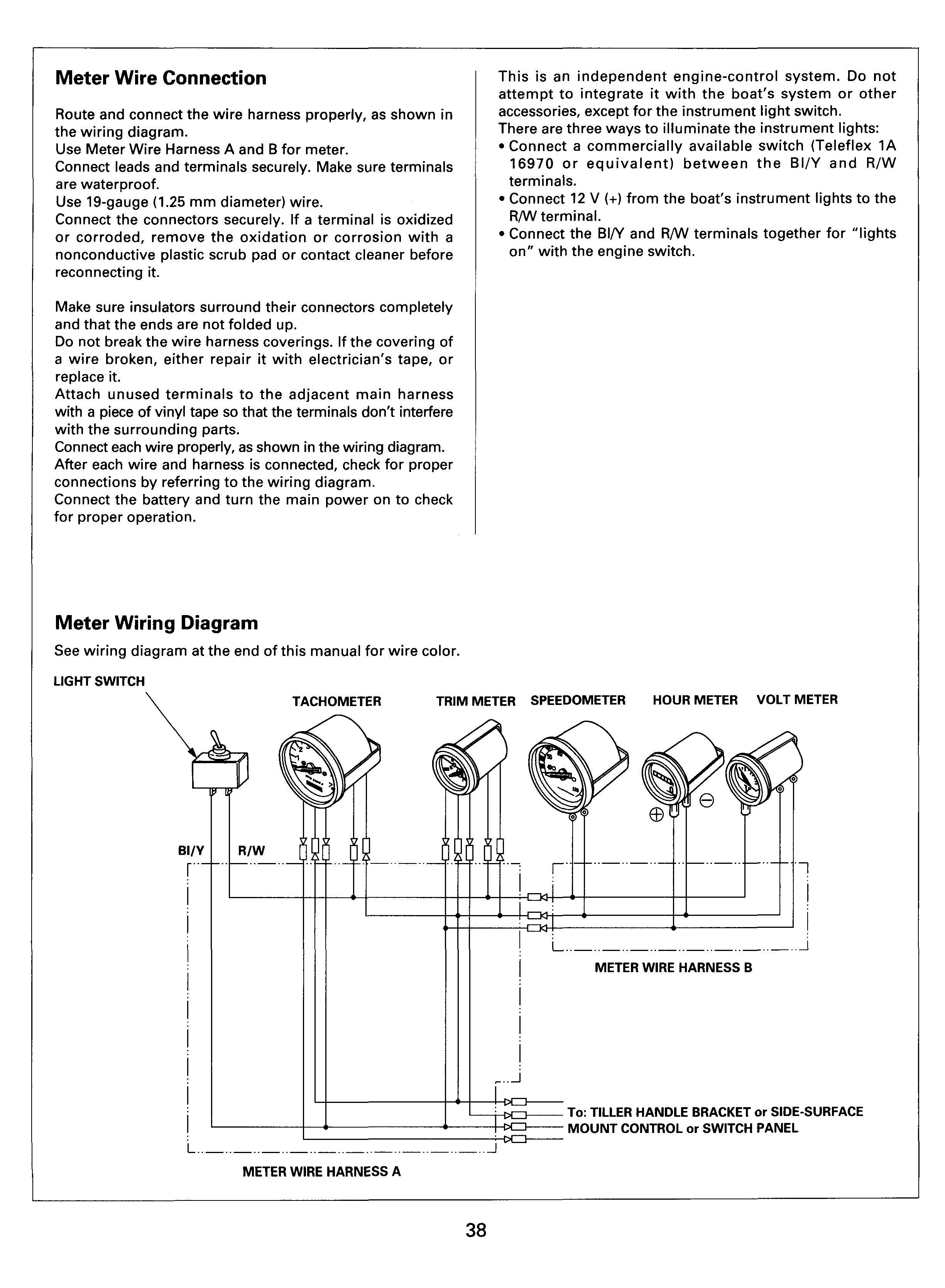
See wiring diagram at the end of this manual for wire color.
LIGHT SWITCH
This is an independent engine-control system. Do not attempt to integrate it with the boat's system or other accessories, except for the instrument light switch. There are three ways to illuminate the instrument lights: Connect a commercially available switch (Teleflex 1A 16970 or equivalent) between the BI/Y and R/W terminals.
Connect 12 V (+) from the boat's instrument lights to the R/W term inaI.
Connect the BW and R/W terminals together for "lights onRwith the engine switch.
To: TILLER HANDLE BRACKET or SIDE-SURFACE MOUNT CONTROL or SWITCH PANEL


