21 minute read
MOTOR INSTALLATION


Motor Selection
Secure and correct installation is essential for safe boating and good performance. Follow the installation instructions provided in this manual.
Improper set-up or pre-deliver service can cause an unsafe condition that can cause your customer to be seriously hurt or killed. Follow the procedures and precautions in this manual and shop manual carefully.
Before installation, check to be sure that the outboard motor does not exceed the recommended maximum horsepower for the boat on which it is to be installed. Refer to the boat's certification plate for recommended maximum horsepower. For most applications, the outboard motor should provide 80% of the recommended maximum horsepower for the boat. If the certification plate information is not available, contact the boat dealer or manufacturer.
Refer to the following dimensional drawings to be sure there is nothing on the boat that will interfere with outboard motor tiltup and steering.
The BF200A and BF225A outboard motors are designed to be installed on boat transom with the following transom board thickness.
Boat transom board thickness: 50 - 70 mm (2-2-3/4 in)
General Guidelines
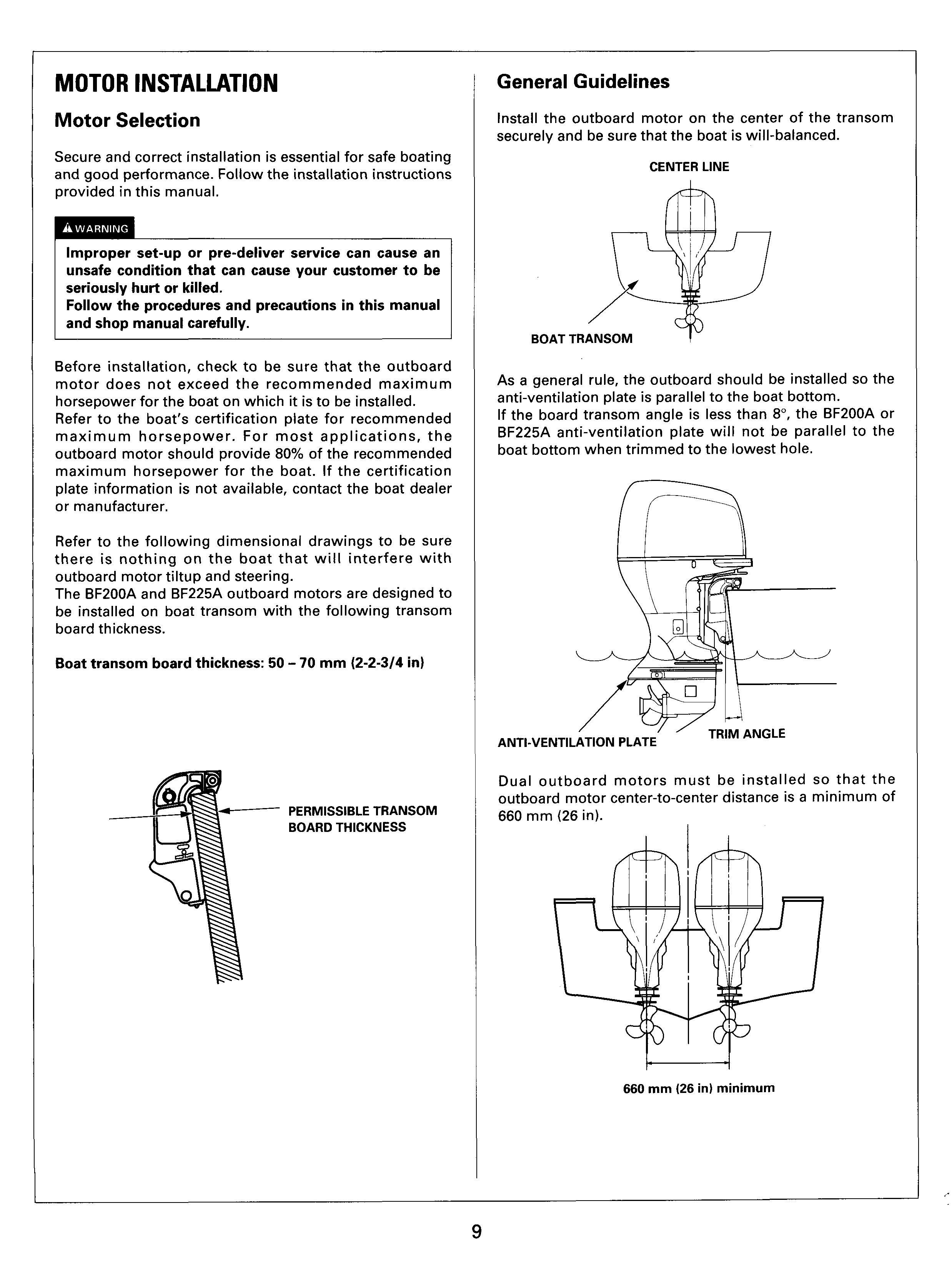
Install the outboard motor on the center of the transom securely and be sure that the boat is will-balanced.
Center Line
Boat
As a general rule, the outboard should be installed so the anti-ventilation plate is parallel to the boat bottom. If the board transom angle is less than 8",the BF200A or BF225A anti-ventilation plate will not be parallel to the boat bottom when trimmed to the lowest hole.
ANTI-VENT11
Dual outboard motors must be installed so that the outboard motor center-to-center distance is a minimum of 660 mm (26 in). I minimum
Boat Transom Center Line
Measure across the transom to determine the transom center line and draw a vertical line. On a "V" bottom boat, the vertical line should pass through the keel.
Use a Dencil and tape measure to locate center line. Put one end of'the tape measure on a chine and place the other end on the upper edge of the transom, somewhere past the "visual" center. Place a mark on the transom and record the distance measured.
Mark
TAPE
Measure the same distance from the opposite chine and make a mark.
Mark
TAPE
Measure the distance between the two marks and place a third mark halfway between them. The line connecting the third mark with the keel is the center line.
If dual outboard motors are to be installed, mark transom at a minimum of 330 mm (13 in) from center line.
Before drilling the holes for installation of the outboard motors, set the outboard motors on the respective center lines and check whether the boat is well-balanced. If a boat is out of balance, adjust by sliding the outboard motor to the adequate position.
Installation Height Check
Optimum outboard motor installation height varies with boat type and bottom shape. Contact the boat manufacture for any special recommendations that are unique to a specific model of boat.
If the outboard motor is installed too low: -The boat will squat and be hard to plane. -The boat high-speed stability will be reduced. -The boat will tend to porpoise.
If the outboard motor is installed too high: -Cavitation may occur when making a turn, which prevents the boat from smooth cruising.
1. Measure the boat transom height.
SINGLE OUTBOARD l9Ornrn (7.5 in)
ANTI-VENTILATION PLATE INNER EDGE
2. Calculate the outboard shaft length requirement. Match the appropriate outboard shaft length to your boat transom height.
On "V" bottom boats, measure the transom height which is the distance from the top edge of the boat transom to the point at which the vertical line passing the inner edge of the anti-ventilation plate intersects with the boat bottom.
Extra long
Extra-extra long
635 mm (25 in)
To determine outboard shaft length requirement, subtract the motor transom height and the boat transom height/ the difference should be approximately 0 - 25mm (0 - 1 in) which is the installation height range.
When mounting dual outboard motors on “V” bottom boats, the outboard installation height range is 0 - 25 mm (0-1 in).
Boat Transom Height Adjustment
If the installation height is too low, or needs to be modified to a accommodate the width of the outboard motor(s), contact the boat’s manufacturer and follow their recommendations for corrective action.
If mounting two outboard motors, be sure the installation height is identical for both.
Some boat manufacturer’s may require different mounting height. Consult your boat manufacturer for specifics on your boat.
3. If the outboard installation height cannot be achieved, adjust boat transom height.
Transom Drilling
Verify no damage will occur when the motor mounting holes are drilled. Lock for any structural impediments such as bulkheads, braces, fuel cells, bilge pumps, or floor sections before drilling.
Ensure there is adequate space for the bolt, .washer, and transom support plate (if applicable), to bear on a flat surface.
Wear safety glasses and drill four 112-inch holes in the transom.
Drill upper holes at least 25 mm (1 in) below transom top edge.
Drill the lower holes in the positions where the top edge of the long hole in the stern bracket comes in contact with the bolt.
1. Mark the center point of the 10 drilling holes (i.e. 5 holes at the right and left sides of the transom respectively that are in the symmetrical position with regard to the center line of the outboard installation line).
e Unit: mm (in)
Bolting Motor to Transom
With motor resting on the boat transom, verify correct motor height. Motor can be raised by using a lower set of mounting holes.
Apply silicone sealant or equivalent to the mounting bolt holes. Secure the motor by installing the bolts from the motor side. Tighten the self-lock nuts. The bolts must have the sufficient thread length to tighten down and have at least two or three threads past the end of the self-lock nut.

TORQUE: 54 Nm (5.5 kgfm, 40 Ibf.ft)
Apply sealant. WASHERS (4) 12x1
LOCK NUTS (4)
WASHERS (8)
If the molding of the transom upper edge interferes with the outboard stern bracket, add the plate or reconditioning the bump and install the outboard stern bracket to the boat transom securely.
Apply sealant.
\ LOCK NUTS (41
’ 013.5 (0.53) -10
2. Using a 3 - 5 mm (0.1 - 0.2 in) diameter drill, drill the pilot holes at the marked points at right angles with the boat transom surface. Then, drill the holes using the 13.5 mm (0.53 in) diameter drill.
3. With the outboard motor resting on the boat transom, verify the correct motor height. The outboard motor can be raised by using a lower set of mounting holes.
4. Use vacuum cleaner to clean up after drilling.
12 x 119 mm BOLTS (4)
Using an air impact tool to tighten or loosen the transom bolts can generate enough heat to damage the bolt threads. The air impact tool can also produce enough tightening torque to damage the boat transom.
Steering Cable Installation
Do this before final placement of the motor on the transom. Refer to the steering cable manufacturer's manual for cable handling procedures. Single outboard:Remove the cap from the steeringhlt tube.
4. Tighten the steering cable nut until the steering cable end play is removed.
TORQUE:
34 - 49 N.m (3.5 - 4.0 kgf.m, 25 - 36 Ibf-ft)
After steering cable nut is torqued, there should be no end play between the outer steering cable and steering/ tilt tube.
For further information regarding the steering cable, refer to boat manufacturer's operation manual.
5. Directly after completing the steering link arm and steering cable installation, verify the following: Motor turns the proper direction when the steering wheel is turned right and left. If the steering is reversed, correct at the steering box.
Motor steering angle is equal when the steering wheel is turned full right and left. If the motor steering angle are not equal:
- Major corrections can be made at the steering box (refer to the steering box or steering cable manufacturer's instructions).
- Minor corrections can be made by moving the steering tilt tube laterally (refer to the Shop Manual).
Apply the marine grease to the inner and outer cable ends. Do not use wheel bearing grease. Install the steering cable through the steeringhilt tube from starboard side.
When the steering cable enters from the port side, the steering/tilt tube must be reversed. Refer to the shop manual for procedures.
Hand-tighten the steering cable cap nut at this time.
Make the steering angles equal as necessary. The steering cable and or steering link arm must not come in contact with any part of the boat when the steering wheel is turned full right and left and all tilt angles. Correct as necessary and check again.
Steering Link Arm Installation
The steering link arm must be secured between the steering plate and steering cable, using the bolt, washers, nuts and collar shown blow. Both the bolt and self-locking nuts, used at each end of the steering link arm, must be in good condition. Install and tighten hardware as follows:
1. Install the bolt, washer and collar into the link arm. Thread the bolt into the steering arm inside hole. Tighten the bolt then tighten the self-lock nut. Do not use forward side hole.
TORQUE:
Bolt: 22 N.m (2.2 kgf.m, 16 Ibf-ft)
Self-locking nut: 18 Nmm(1.8 kgf-m, 13 Ibfmft)
2. Turn the steering wheel to extend the steering cable out of the steeringhilt tube. Connect the steering cable and the steering link arm using the nut and washers.
3. Turn the steering wheel to retract the steering cable into the steeringhilt tube. Tighten the steering link arm to the steering cable with the self-locking nut to a torque of 10 N.m (1.0 kgf.m, 7 Ibf.ft), then loosen the self-locking nut 118 turn.
3/8-24 UNF BOLT (Optional equipment)
WASHERS (3) (Optional equipment) COLLAR (Optional equipment) / STEERING LINK ARM (Optional equipment)
Tie Bar Installation (Dual motors)
1. As previously described, install the steering cable and the steering link arm.
2. Install a commercially available tie bar in the steering plate hole using the bolt, washers and self-locking nut.
3/8-24 UNF HEX BOLT WASHER (2)
/ & 3/8-24 UNF SELF-LOCKING (Marine grease) NUT (2) (Optional equipment)
3/8-24 UNF SELF-LOCKING NUT
3. After installation, test run the outboard motors and adjust the tie bar (see page 47).
REMOTE CONTROL BOX (Optional equipment)
SIDE-MOUNT REMOTE CONTROL
GEARSHIFT/THROTTLE CONTROL LEVER
NEUTRAL RELEASE LEVER
POWER TRIM/TILT SWITCH
SPARE EMERGENC STOP SWITCH CLIP
OIL PRESSURE INDICATOR LIGHT
OVERHEAT INDICATOR LIGHT
FAST IDLE LEVER
IGNITION SWITCH BUZZER (inside)
CONTROL LEVER FRICTION ADJUST
EMERGENCY STOP SWITCH
EMERGENCY STOP SWITCH CLIP
EMERGENCY STOP SWITCH LANYARD
The fast idle lever is only needed for starting carbureted outboard models. The BF2OOA and BF225A models use programmed fuel injection so, this lever will not be needed for starting.
After the engine starts and if the outside temperature is below 41°F (5"C), the fast idle lever can be used to accelerate engine warm up.
MAXIMUM FAST IDLE
N (NEUTRAL)
F (FORWARD1 30"
LOWEST POSITION
I
FAST IDLE LEVER
Top Mount Remote Control
This section shows you the right-hand handle type only. The right-hand remote control is designed so that you can perform the throttle operation and the tilt angle adjustment with your right hand. Note that the name and operation of each part of the left-hand handle type are identical with those of the right-hand handle type.
GEARSHIFT/THROTTLE CONTROL LEVER
POWER TRIM/TILT
POWER TRIM/TILT SWITCH
CONTROL LEVER
POWER TRIM/TILT SWITCH (LEFT)
FAST IDLE BUlTON
The first idle button is only needed for starting carbureted outboard models. The BF200A and BF225A models use programmed fuel injection so, this lever will not be needed for starting.
After the engine starts and if the outside temperature is below 41°F (5"C), the fast idle lever can be used to accelerate engine warm up.
The illustration shows the remote control lever operation when the right-hand handle type remote control is mounted on the right side. Left-hand handle type remote control operation mounted on the left side is the mirror image of the above illustration.
SPACER (Optional equippmentl
The spacer is not included in remote control kit. It is available as an optional part. Purchase a genuine Honda spacer for the outboard motor remote control kit as needed.
Note that the installation height of the remote control increase 25 mrn (0.98 in) by mounting the spacer. Check the spacer installation and the surrounding area for freedom from interference and restriction.
For single lever type:
(0.98 in)
For dual lever type:
CONTROL PANEL (for PANEL/TOP MOUNT type)
The switch panel is not included in the remote control kit. It is available as an optional part. Purchase this genuine Honda part as needed.
OIL PRESSURE INDICATOR LIGHT
OVERHEAT INDICATOR LIGHT
EMERGENCY
EMERGENCY STOP SWITCH STOP SWITCH C
EMERGENCY STOP SWITCH
Cable Selection
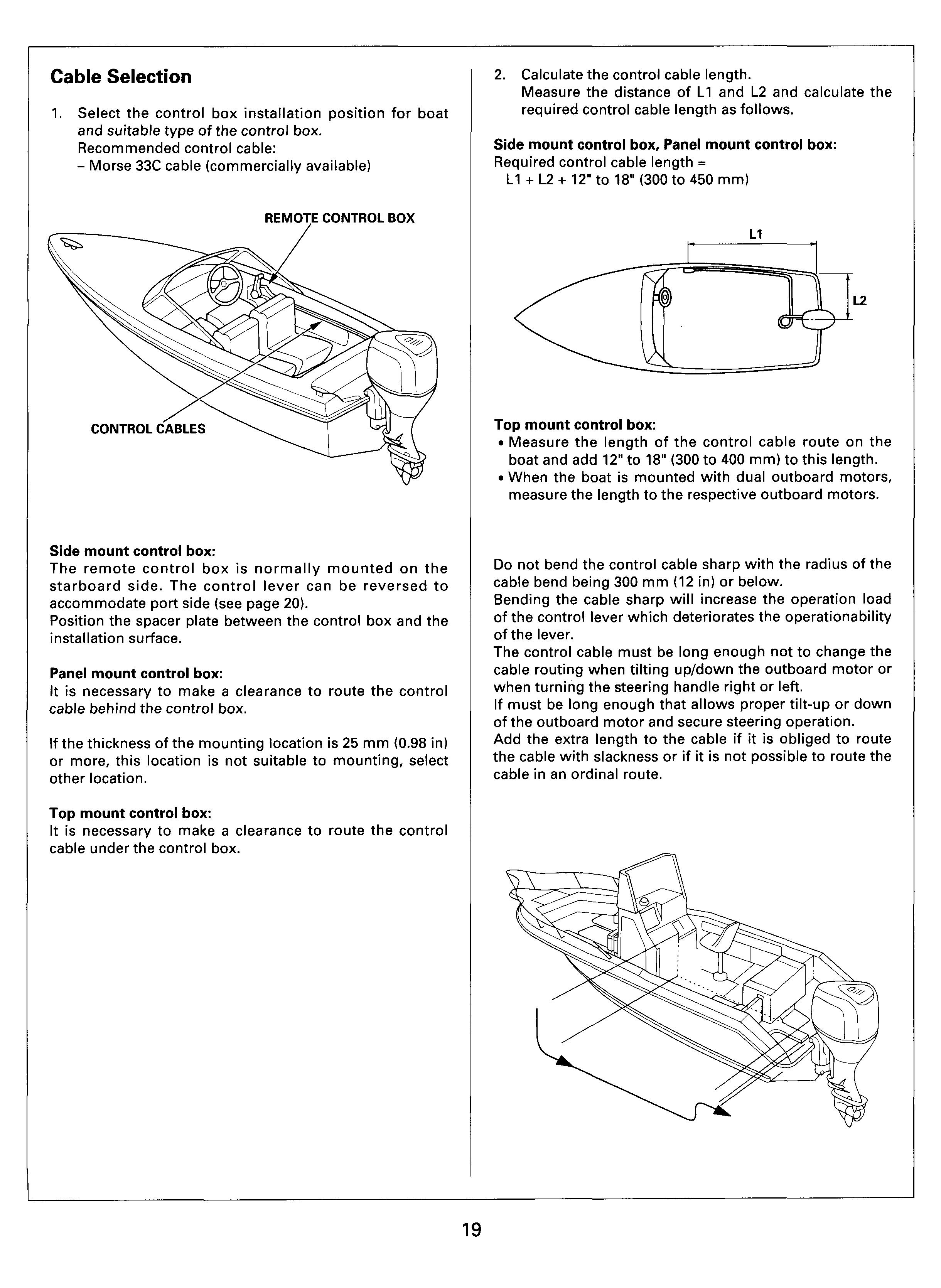
1. Select the control box installation position for boat and suitable type of the control box. Recommended control cable: - Morse 33C cable (commercially available)
Remote Control Box
2. Calculate the control cable length. Measure the distance of L1 and L2 and calculate the required control cable length as follows.
Side mount control box, Panel mount control box: Required control cable length = L1 + L2 + 12" to 18" (300 to 450 mm)
Side mount control box:
The remote control box is normally mounted on the starboard side. The control lever can be reversed to accommodate port side (see page 20). Position the spacer plate between the control box and the installation surface.
Panel mount control box:
It is necessary to make a clearance to route the control cable behind the control box.
If the thickness of the mounting location is 25 mm (0.98 in) or more, this location is not suitable to mounting, select other location.
Top mount control box:
It is necessary to make a clearance to route the control cable under the control box.
Top mount control box: Measure the length of the control cable route on the boat and add 12" to 18" (300 to 400 mm) to this length. When the boat is mounted with dual outboard motors, measure the length to the respective outboard motors.
Do not bend the control cable sharp with the radius of the cable bend being 300 mm (12 in) or below.
Bending the cable sharp will increase the operation load of the control lever which deteriorates the operationability of the lever.
The control cable must be long enough not to change the cable routing when tilting up/down the outboard motor or when turning the steering handle right or left. If must be long enough that allows proper tilt-up or down of the outboard motor and secure steering operation. Add the extra length to the cable if it is obliged to route the cable with slackness or if it is not possible to route the cable in an ordinal route.
Reversing Control Lever
This side mount control box is available designed to be mounted on the starboard side. It can be mounted on the port side by reversing the control lever installation in the following procedure.
1. Remove the two screws and remove the housing cover C.
HOUSING COVER C
4. Set the control lever in the neutral position. Remove the 8 mm lever lock bolt and remove the control lever with care not to damage the power trim/tilt switch harness.
Control Lever
Screws
2.
3.
Remove the two screws and remove the hold-down plate. Disconnect the power trimhilt switch harness connector.
5. Remove the two screws and remove the neutral lock block.
Neutral Lock Block
HOLD-DOWN PLATE , CONNECTOR
6. Install the neutral lock block on the reverse side of the control box with the two screws.
I NEUTRAL LOCK BLOCK
7. Install the control lever from the housing B side in the neutral position.
Align the groove in the switch wire grommet with the cutout in the housing B.
Pass the power trim/tilt switch harness as shown and connect the connector.
Install the power tilt cord clamp with the two screws.
POWER TRIM/TILT SWITCH WIRE
CONTROL LEVER
SCREW
POWER TILT CORD CLAMP CONNECTOR
10. Tighten the 8 mm lock bolt with washer.
TORQUE: 20 N.m (2.0 kgf.m, 14 Ibf.ft)
WASHER
8 mm LOCK BOLT
11. Install the housing cover C and tighten the two screws. Do not overtighten the screws.
TORQUE: 2 N.m (0.2 kgf-m, 1.4 Ibf-ft)
SCREWS
HOUSING COVER C
Cable Connection
Route and connect the control cables to the remote control box before connecting them to the motor.
1. Remove the two screws and remove the housing cover C.
3. Aligning the groove in the shift cable with the cable guide, connect the shift cable to the control box.
4. Connect the shift pivot to the shift lever.
SHIFT CABLE n SHIFT LEVER
SCREW \ HOUSING COVER C
2. Screw in the nut and the shift pivot on the control box side of the control cable to the position shown. Screw in the shift pivot 8 mm (0.3 in) or more from the end of the control cable and tighten the lock nut securely. Apply marine grease to the joint of the shift pivot.
NUT
8 mm (0.3 in) or more
CABLE‘7u GUIDE
5. Install the cable clamp spacer.
6. Install the throttle cable by aligning the groove in the cable with the cable guide.
7. Connect the shift pivot to the shift lever.
8. Install the housing cover C with the two screws.
HOUSING COVER C
SCREWS (2) /
Control Box Installation Side Mount Control Box
This control box is designed to be mounted on the starboard side. When it is mounted on the port side, reverse the control lever installation for the port mount type (see page 18). Set a spacer between the control box and the boat to obtain the clearance for operation of the lever. Connect the control cable to the control box before installing the control box.
Select the control box installation position for boat and suitable type of the control box.
Recommended installation position:
- Convenient for the control lever operation
- Free from interference or restriction in routing the cables and harnesses between the control box and the outboard motor.
- Near a corner of the driver’s seat.
- Underside of the control box is level with the upper surface of the seat.
Set the remote control box at the installation position and mark the drilling points for the control box mounting screws.
Drill at the marked points using the 7 mm-diameter drill.
Connect the control cables to the remote control box (see page 22).
Install the remote control box using the washers, nuts and the screws.
Set the spacer and washers between the remote control box and the mounting surface on the boat as shown to obtain the clearance for smooth operation of the control lever.
Install the control box with the control lever set in the neutral position.
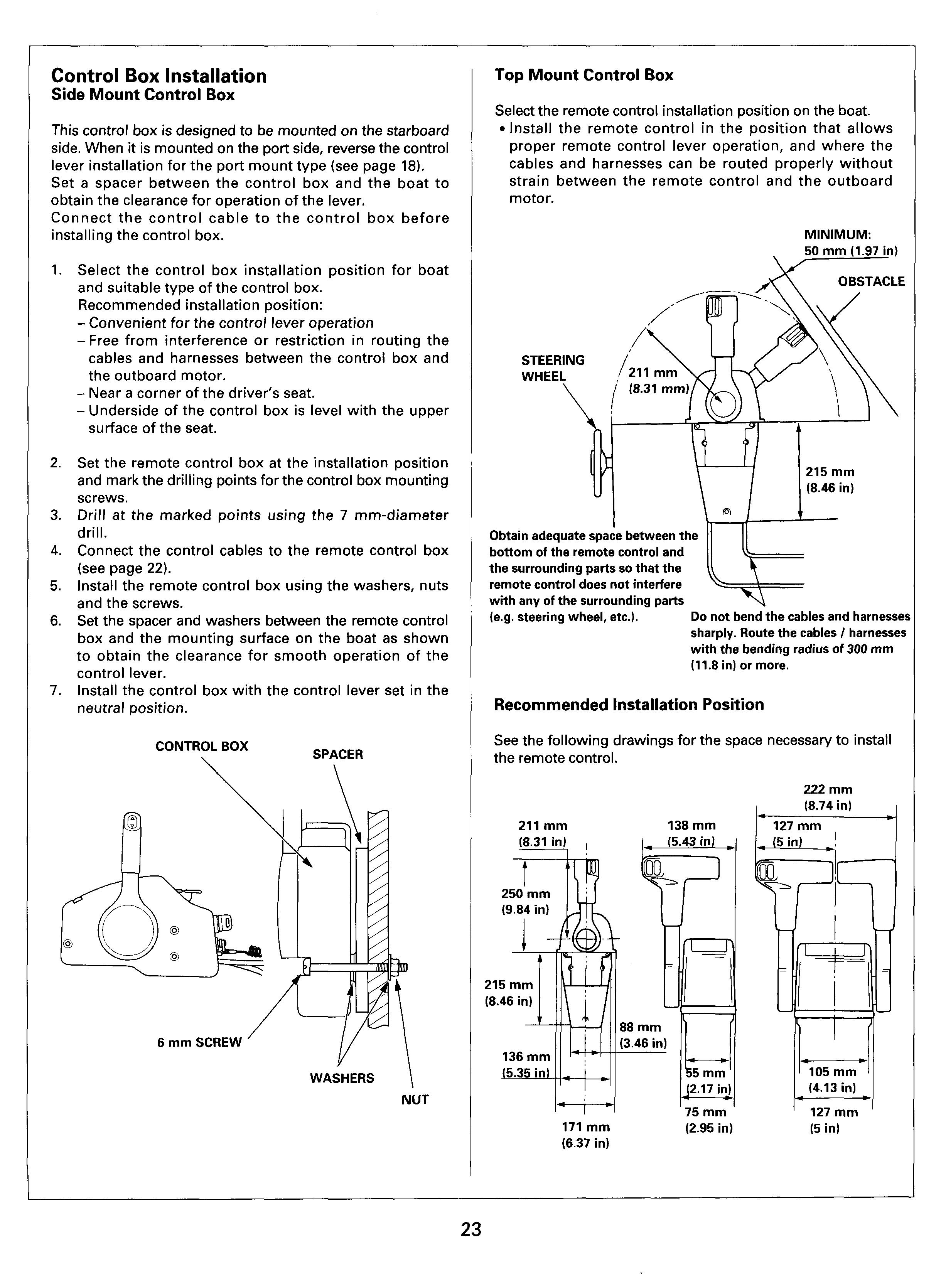
Top Mount Control Box
Select the remote control installation position on the boat. Install the remote control in the position that allows proper remote control lever operation, and where the cables and harnesses can be routed properly without strain between the remote control and the outboard motor.
Obtain adequate space between the bottom of the remote control and the surrounding parts so that the remote control does not interfere with any of the surrounding parts (e.g. steering wheel, etc.). Do not bend the cables and harnesses sharply. Route the cables I harnesses with the bending radius of 300 mrn (11.8 in) or more.
See the following drawings for the space necessaw to install the remote control.
Both the single and the dual lever type remote controls are available in the right-hand handle type and the lefthand handle type respectively. Select the correct type for the boat.
LEFT-HAND HANDLE RIGHT-HAND HANDLE SINGLE LEVER TYPE SINGLE LEVER TYPE
33C Cable and Cable End Installation
Screw on the cable end over the threaded part at the end of the control cable and secure with the lock nut not to allow the cable end to turn.
Screw in the cable end fully to the end to the shaded part in the drawing.
Control Cable Routing
Top mount control: Measure the control cable routing length along the actual cable route, and add 300 - 450 mm (11.8 - 17.72 in) to the measurement.
Dual mount remote control:
Measure the control cable routing length to the respective outboard motors.
Top Mount Remote Control Installation (Right-hand handle, Single lever type)
This section explains the installation procedure of the right-hand handle single lever type remote control. The left-hand handle single lever type remote control and the left-hand / right-hand handle dual lever type remote controls can be installed in the same manner.
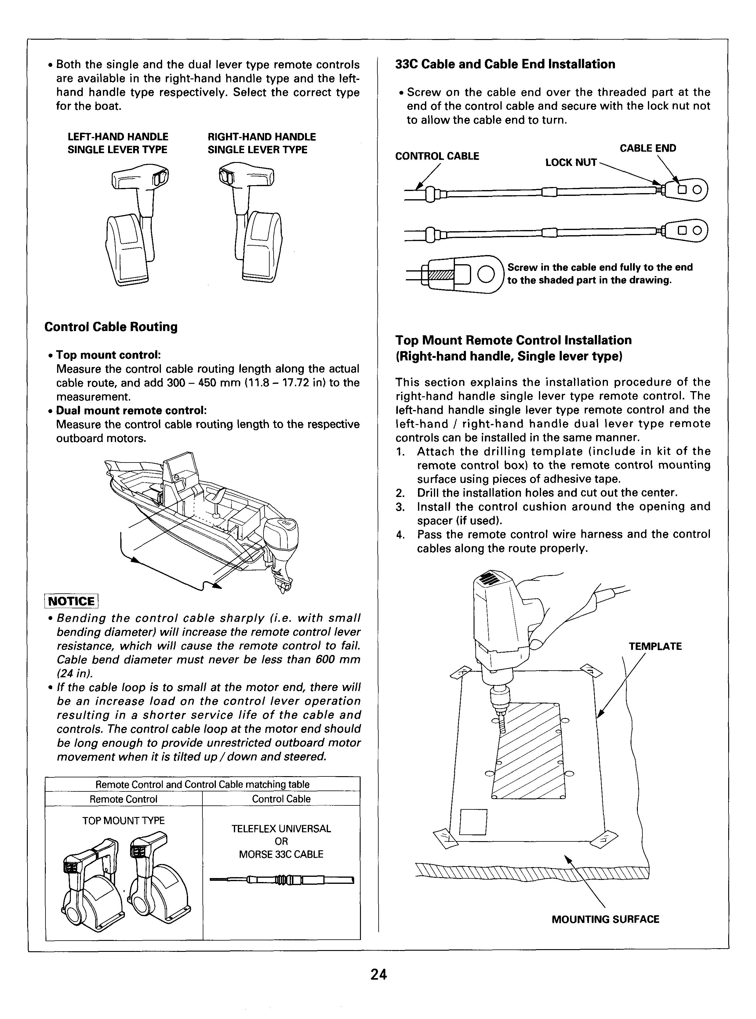
Attach the drilling template (include in kit of the remote control box) to the remote control mounting surface using pieces of adhesive tape.
Drill the installation holes and cut out the center. Install the control cushion around the opening and spacer (if used).
Pass the remote control wire harness and the control cables along the route properly.
Bending the control cable sharply (i.e. with small bending diameter) will increase the remote control lever resistance, which will cause the remote control to fail. Cable bend diameter must never be less than 600 mm (24 in).
If the cable loop is to small at the motor end, there will be an increase load on the control lever operation resulting in a shorter service life of the cable and controls. The control cable loop at the motor end should be long enough to provide unrestricted outboard motor movement when it is tilted up/down and steered.
Remote Control
Control Cable
TOP MOUNT TYPE TELEFLEX UNIVERSAL OR MORSE 33C CABLE
Remote the cover and the other parts as shown.
10. Apply marine grease to the throttle cable pin where it connects to the throttle arm.
11. Connect the throttle control cable to the throttle arm, in the same manner as the gearshift control cable, with an E-ring.
HOUSING BRACKET
CONTROL CUSTN
Remove the screw and remove the back plate form the inner housing.
SCREWS
THROTTLE
(Marine grease)
12. Install the back plate and the housing bracket in the reverse order of removal.
13. Install the remote control as shown. Be sure to connect the switch wire to the remote control wire harness before installation.
SCREWS
Apply marine grease to both the shift and throttle pins at the end of each arm.
Install the gearshift control cable groove in the housing clamp groove. Insert the cable end into the pin at the end of the shift arm, and secure with an Ering.
Insert the cable clamp spacer in the clamp groove.
SHIFT ARM
(Marine grease)
CONTROL CABLE
CLAMP GROOVE
CABLE CLAMP
14. Use the guide plate (provided with the kit) and install the cover and the housing lead. Follow the instructions on the guide plate carefully.
Spacer Installation (Optional equipment)
Install the spacer, if necessary, between the control cushion and the mounting surface as shown, and secure with the 5 x 65 mm screws, 5 rnrn washers and 5 rnrn nuts (provided with the spacer).
/ COVER
HOUSING LEAD
GUIDE PLATE
MOUNTING SURFACE
5 mm WASHER
Control Lever Friction Adjustment
Side Mount Control Box
Adjust the friction by turning the control lever friction adjuster.
CONTROL LEVER FRICTION ADJUSTER
Top Mount Control Box
Adjust the friction by turning the control lever friction adjuster.
1. Remove the two screws, cover and the housing lead. SCREWS (2)
HOUSING LEAD friction
2.
3.
CONTROL LEVER FRICTION ADJUSTER
Adjust the friction by turning the control lever friction adjuster
After adjusting, install the housing lead, cover and the two screws securely.
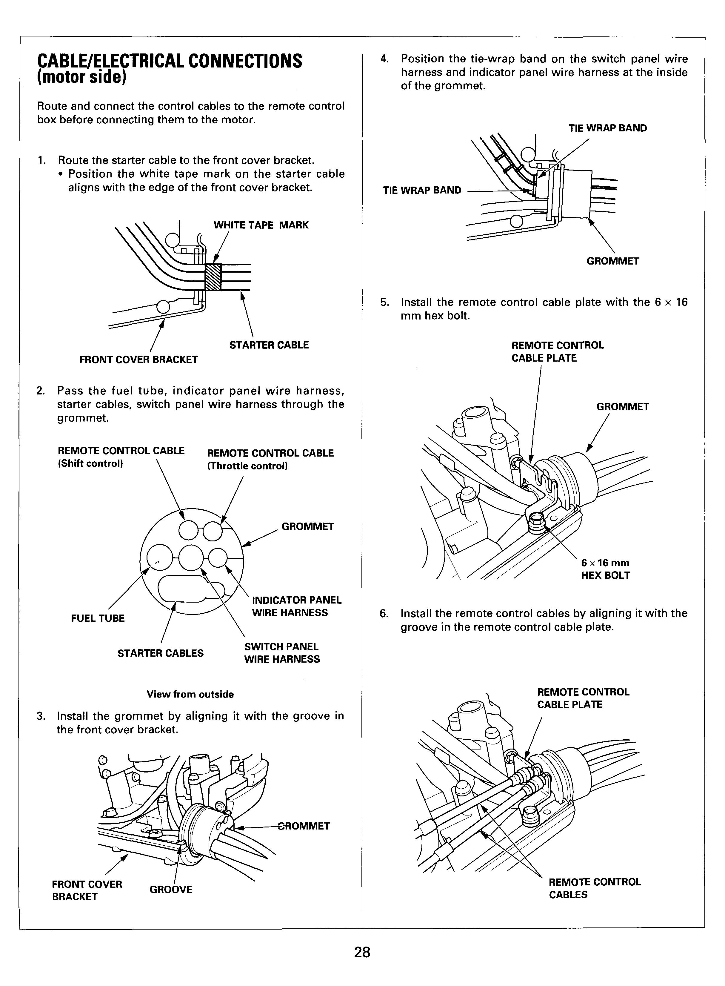
CABLE/ELECTRICAL CONNECTIONS (motor side)
Route and connect the control cables to the remote control box before connecting them to the motor.
Route the starter cable to the front cover bracket. Position the white tape mark on the starter cable aligns with the edge of the front cover bracket.
WHITE wTAPE MARK
/ STARTER CABLE
FRONT COVER BRACKET
Pass the fuel tube, indicator panel wire harness, starter cables, switch panel wire harness through the grommet.
IWWTE ~ONTROLCABLE (Shift control)
FUEL TUBE
4. Position the tie-wrap band on the switch panel wire harness and indicator panel wire harness at the inside of the grommet.
TIE WRAP BAND
TIE WRAP BAND
GROMMET
5. Install the remote control cable plate with the 6 x 16 mm hex bolt.
REMOTE CONTROL CABLE PLATE
STARTER CABLES
REMOTE CONTROL CABLE GROMMET
(Throttle control)
INDICATOR PANEL WIRE HARNESS
SWITCH PANEL WIRE HARNESS
6. Install the remote control cables by aligning it with groove in the remote control cable plate.
View from outside
Install the grommet by aligning it with the groove in the front cover bracket.
\ REMOTE CONTROL
OMMET
I
FRONT COVER GROOVE BRACKET
REMOTE CONTROL CABLES
Tighten the grommet with the band securely. Make sure the fuel tube is not pinched by the grommet.
Grommet
Shift Cable Connection
1. Install the shift pivot to the remote control cable.
2. Move the control lever to the full forward "F" position.
3. Then slowly return the control lever to the neutral "N" position, and make a mark (A) on the inner cable at the end of the outer cable seal as shown.
MARK A
OUTER CABLE I "N"
IBAND
Connect the main wire harness 14P connector to the switch panel wire harness connector and the 3P connector to the indicator panel wire harness connector, then attach them to the connector holders.
Clamp the switch panel wire harness and the indicator panel wire harness with the harness clip.
HOLDERS
INDICATOR PANEL A
HARNESS CLIP ' SWITCH PANEL WIRE HARNESS
Iouter Cable Seal
4. Move the control lever to the full reverse "R" position.
5. Then slowly return the control lever to the neutral "N" position, and make a mark (B) on the inner cable at the end of the outer cable seal as shown.
MARK B \ "N "
6. Make a mark (C) at the center between the A and B marks.
MARKC MARKB
MARK A
7. Apply marine grease to the joint hole of the shift pivot and shift link.
8. Adjust the shift pivot until it will attach to the shift link.
9. Attach the shift pivot to the shift link, then tighten the lock nut securely.
12 Make sure that outboard motor in the neutral position; shift arm tip aligns with the neutral switch tip and the detent roller is set in the groove in the shift arm.
SHIFT LINK ROD
10. Make sure that the shift pivot is in the center of the shift link joint hole, adjust by turning the shift pivot if necessary.
Shift'arm tip aligns with the neutral switch tip.
13. After attaching the shift cable to the shift link, check for smooth operation by moving the remote control lever to forward and reverse positions.
SHIFT LINK ROD
11. If necessary, loosen the lock nut and turn the shift pivot for adjusting. After adjusting, tighten the lock nut securely.
SHIFT PIVOT
14. Make sure that the shift link moves smoothly and returns to the neutral detent position when the remote control lever is returned to the neutral.
CAUTION:
If it is hard to shift, turn propeller shaft. Shifting with force will damage the shift mechanism.
If shift arm moves smoothly and neutral detent aligns, tighten the cable lock nut securely.
If the shift position is not in neutral position when the shift lever moves from forward position to neutral position, loosen the lock nut of the shift pivot and turn the shift pivot close to mark (A). After adjusting, tighten the lock nut.
ADJUSTABLE RANGE
If the shift position is not in neutral position when the shift lever moves from reverse position to neutral position, loosen the lock nut of the shift pivot and turn the shift pivot close to mark (B). After adjusting, tighten the lock nut.
ADJUSTABLE RANGE
Throttle Cable Connection
1. Apply marine grease to the joint hole of the shift pivot and throttle arm link.
2. Adjust the shift pivot until it will attach to the throttle arm link.
3. Install the shift pivot to the throttle arm link, then tighten the lock nut securely.
(Marine grease)
4. Move the remote control lever to the full throttle position.
5. Make sure that the throttle arm contacts the throttle arm stopper. Adjust by turning the shift pivot if necessary.
6. After adjustment, recheck and tighten the lock nut.
Markc Mark B
I
Front Separate Cover Installation
1. Install the front separate cover and tighten the bolts securely.
FRONT 6 mm SEPARATE COVER WASHER
Electric Parts Cover Installation
1. Install the cover lightly so that the plastic knobs align with the holes of the grommets.
Electric Parts Cover
Plastic Knobs Rubber Strap Grommets
6x37mm SPECIAL BOLTS
\ 6xl7mm SPECIAL BOLT
2. After installing the cables and wire harnesses to the motor, remove the bolts, nut and the bracket from the steering arm.

ENGINE COVER MOUNTING BOSSES (check for proper alignment with electrical parts cover)
2. Install the electrical parts cover and secure with the rubber strap. Make sure the electrical parts cover is properly aligned with the engine cover mounting bosses.
Notice 1
To install the cover securely, make sure the remote control cable, switch panel wire harness and the indicator wire harness are installed securely.
If the electrical parts cover is pushed hard and the plastic knobs are not aligned with the grommets, the plastic knobs may break.
The electrical parts cover must be installed correctly to allow the engine cover to insert into the engine cover mounting bosses.
SWITCH PANEUINDICAT0R PANE1 Switch Panel Installation
When the panel mount control box or the top mount control box is used, install the switch panel on the boat at the position near the driver's seat.
1. Determine the switch panel installation position. It should be near the driver's seat where the switch panel does not interfere with the driving operation.
2. Attach the template shown at the end of this manual at the switch panel installation position.
3. Drill the holes according to the indication on the template.
4. Install the switch panel by tightening the four 5 x 40 mm screws, four 5 mm washers, four 5 mm spring washers, and the four 5 mm flange nuts.
Indicator Panel Installation
1. Determine the indicator panel installation position.
2. Attach the template shown at the end of this manual at the indicator panel installation position.
3. Drill the holes according to the indication on the template.
4. Install the indicator panel by tightening the four 5 x 40 mm screws, four 5 mm washers, four 5 mm spring washers, and the four 5 mm flange nuts. Clamp the indicator panel wire harness with the cable clamp to prevent damage to the harness caused by vibration.
5. INDICATOR PANEL
5 x 40 mm SCREWS (4)
5 mm SPRING WASHERS (4)
5 mm FLANGE NUTS (4)
CABLE CLAMP INDICATOR:I"HARNESS
\ 5 mm FLANGE NUTS (4)


