23 minute read
OPERATING CONTROLS


during crane shutdown periods or anytime the crane is left unattended.
1. Perform the procedures found under Shutdown Procedure in this manual.
Danger
Never park crane near holes, on rocky surfaces, or on soft spots. This may cause crane to overturn, resulting in injury or death to personnel.
2. Park the crane on a proper surface with the outrigger stabilizers and beams fully retracted. Do not park in a location where it may become frozen to the ground or settle unevenly and overturn.
3. Apply parking brakes and if necessary, chock the wheels.
4. Position all controls to neutral or off.
5. Shut down the engine using the proper procedures as specified by this manual and the engine manual.
6. Perform any other specified procedures required at the end of the workday, i.e., drain water from the fuel filterwater separator, refueling, etc.
7. Close all windows.
8. Remove the keys from the crane.
9. Lock up the crane. Install vandal guards, if used.
Caution
Step 10 does not take the place of the prestarting checks which must be performed just prior to using the crane at the next working day.
10. Make a thorough walk around inspection to ensure that all cylinders that can be retracted are retracted. The only exceptions are those cylinders which cannot be fully retracted, i.e., steer cylinders. Also, look for anything that could hinder or prevent starting the next day’s work.
Unattended Crane
Warning
Tipping Hazard!
Changing weather conditions including but not limited to: wind, ice accumulation, precipitation, flooding, lightning, etc. should be considered when determining the location and configuration of a crane when it is to be left unattended.
Failure to comply with these instructions may cause death or serious injury.
The configuration in which the crane should be left while unattended shall be determined by a qualified, designated individual familiar with the job site, configuration, conditions, and limitations.
General
This section provides procedures for installing the hoist cable on the hoist drum, cable reeving, and erecting and stowing the boom extension, and removal and installation of the counterweight.
Installing Cable On The Hoist
Caution
If cable is wound from the storage drum, the reel should be rotated in the same direction as the hoist.
NOTE: The cable should preferably be straightened before installation on the hoist drum.
Install cable on the hoist drum in accordance with the following procedure.

1. Position the cable over the boom nose sheave and route to the hoist drum.
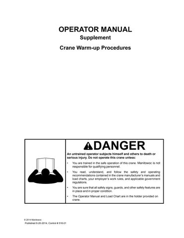
2. Position the hoist drum with the cable anchor slot on top.
3. Insert the cable through the slot and position around the anchor wedge (1) (Figure4-1).
NOTE: The end of the cable should be even with the bottom of the slot for the anchor wedge.
4. Position the anchor wedge in the drum slot; pull firmly on the free end (2) of the cable to secure the wedge.
NOTE: If the wedge does not seat securely in the slot, carefully tap (3) the top of the wedge with a mallet.
5. Slowly rotate the drum, ensuring the first layer of cable is evenly wound onto the drum.
6. Install the remainder of the cable, as applicable.
Cable Reeving
NOTE: There are two types of cable (wire rope) available on this crane; 6x37 and 35 x 7 (non-rotating).
Within the limits of the load and range charts and permissible line pull, multi-part lines allow the operator to raise a greater load than can be raised with a single part line. Various cable reeving (part line) is possible with the boom nose and hook block. This reeving should be accomplished by a qualified rigger using standard rigging procedures (Figure4-3)
In order to quick reeve the hook block without removing the wedge socket on the end of the cable, refer to Figure4-2.
UPPER BOOM NOSE SHEAVES
BOTTOM BOOM NOSE SHEAVES
3rd
4th
UPPER BOOM NOSE SHEAVES
TO MAIN HOIST
TO AUX HOIST
BOTTOM BOOM NOSE SHEAVES
BOOM NOSE DEAD END
UPPER BOOM NOSE SHEAVES
TO MAIN HOIST
BALL
FOUR PARTS LINE
HOOKBLOCK SHEAVES
AUX. NOSE
BALL
3 SHEAVE HOOKBLOCK
SIX PARTS LINE
TO AUX HOIST
BOTTOM BOOM NOSE SHEAVES BOOM NOSE DEAD END
Published 2-20-2012, Control # 433-00
HOOKBLOCK SHEAVES
UPPER BOOM NOSE SHEAVES
TO MAIN HOIST
TO AUX HOIST
BOTTOM BOOM NOSE SHEAVES
AUX. NOSE
BALL
HOOKBLOCK SHEAVES
FOUR PARTS LINE
BOOM NOSE DEAD END
UPPER BOOM NOSE SHEAVES
TO MAIN HOIST
TO AUX HOIST
BOTTOM BOOM NOSE SHEAVES
BOOM NOSE DEAD END AUX. NOSE
BALL
SIX PARTS LINE
TMS750E - 4 SHEAVE HOOKBLOCK
HOOKBLOCK SHEAVES
FIGURE 4-3 continued
UPPER BOOM NOSE SHEAVES
TO MAIN HOIST
BOTTOM BOOM NOSE SHEAVES
BOOM NOSE DEAD END
HOOKBLOCK SHEAVES
DEAD-END RIGGING/WEDGE SOCKETS
Wedge socket assemblies are popular rigging accessories and have been successfully used for decades to terminate wire ropes on mobile cranes. A wedge socket assembly is easily installed and dismantled but it must be installed and used correctly. It is essential to use only a wedge and socket of the correct size for the rope fitted. Failure to do so may result in the rope pulling through the fitting.
Since state and local laws may vary, alternate attachment methods may be necessary depending upon work conditions. If alternate methods are selected, the user is responsible and should proceed in compliance with the regulations in force. If there are any questions, contact your local distributor or Manitowoc Crane Care.
Do not mix components from different manufacturers. The selection, installation and use of a wedge socket assembly must be in accordance with the requirements of the wedge socket manufacturer and the wire rope manufacturer upon whose wire rope the wedge socket assembly will be used.
Manitowoc Cranes specifies the size, type, class and line pulls for wire rope, predominately rotation resistant wire rope, and rigging accessories such as overhaul balls and hook blocks for use with each new crane that it manufactures. Other wire ropes and rigging accessories are available from various vendors. Different wire rope manufacturers have differing requirements for the construction, handling, cutting, seizing, installation, termination, inspection and replacement of the wire ropes they produce. Their advice should be sought for each specific type of wire rope a crane user intends to install on a mobile crane.
When assembly is complete, raise the boom to a working position with a load suspended to firmly seat the wedge and rope into the socket before the crane is used operationally.
Caution
If the socket is not positioned with the flat face toward the boom sections, structural damage will occur.
When anchoring the socket to the boom (Figure4-4), ensure the flat face of the socket is in position, as shown, toward the boom sections.
Installing Wedge and Socket
1. Inspect the wedge and socket. Remove any rough edges and burrs.
2. The end of the wire rope should be seized using soft, or annealed wire or strand. If the end of the rope is welded, the welded end should be cut off. Do not weld on size 6X37 rope. This will allow the distortion of the rope strands, caused by the bend around the wedge, to adjust themselves at the end of the line. Refer to Section 1 - Introduction in the Service Manual for wire rope procedures.
3. Make sure the live-end (Figure4-5) of the rope is directly in line with the ears of the socket and the direction of pull to which the rope will be subjected. If the rope is loaded into the socket incorrectly, under a load the rope will bend as it leaves the socket, and the edge of the socket will wear into the rope causing damage to the rope and eventual failure.
4. Insert the end of the wire rope into the socket, form a loop in the rope, and route the rope back through the socket allowing the dead-end (Figure4-5) to protrude from the socket. Ensure the dead-end of the rope is of sufficient length to apply end treatment to the dead-end after the wedge has been seated.
5. Insert the wedge into the loop and pull the live-end of the rope until the wedge and rope are snug inside the socket. It is recommended that the wedge be seated inside the socket to properly secure the wire rope by using the crane’s hoist to first apply a light load to the live-end.
6. After final pin connections are made, increase the loads gradually until the wedge is properly seated.
7. The wire rope and wedge must be properly secured inside the socket before placing the crane into lifting service. It is the wedge that secures the wire rope inside the socket. The dead-end treatment is used to restrain the wedge from becoming dislodged from the socket should the rope suddenly become unloaded due to the headache ball or hook block striking the ground, etc.
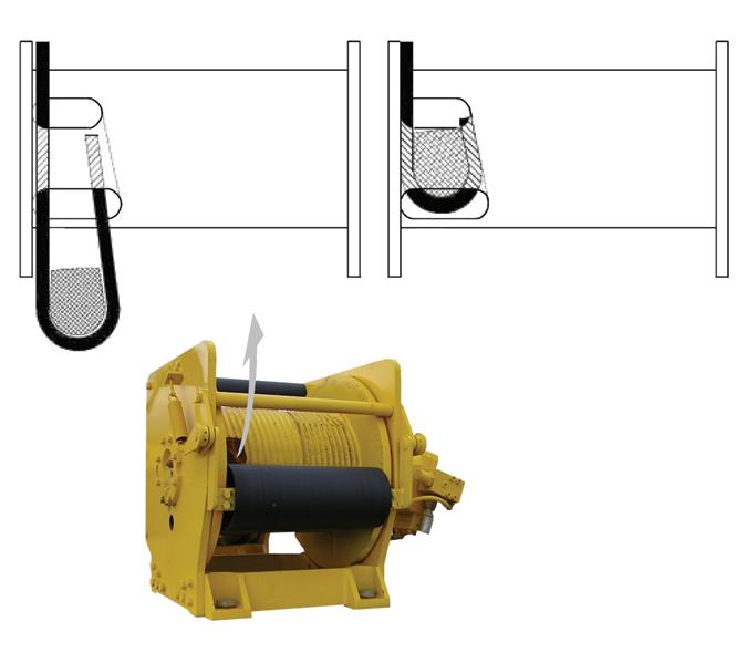
Sketches A through F (Figur e4-6) illustrate various ANSI approved methods for treating the dead-ends of wire ropes which exit a wedge socket assembly. While use of the loopback method is acceptable, care must be exercised to avoid the loop becoming entangled with tree branches and other components during crane transport and with the anti-two block system and other components during use of the crane.
Of the methods shown below, Manitowoc prefers that method A or F be used, i.e., clipping a short piece of wire rope to the dead-end or using a commercially available specialty wedge. Typically, it is recommended that the tail length of the dead-end should be a minimum of 6 rope diameters but not less that 6in (15.2cm) for standard 6 to 8 strand ropes and 20 rope diameters but not less than 6in (15.2cm) for rotation resistant wire ropes.
When using method A, place a wire rope clip around the dead end by clamping a short extra piece of rope to the rope dead end. DO NOT CLAMP THE LIVE END. The U-bolt should bear against the dead end. The saddle of the clip should bear against the short extra piece. Torque the U-bolts according to the table titled Wire Rope Clip Torque Values (Table 4-1).
Other sources for information with which crane users should be familiar and follow is provided by the American Society of Mechanical Engineers, American National Standard, ASME B30.5, latest revised. ASME (formerly ANSI) B30.5 applies to cableways, cranes, derricks, hoists, hooks, jacks, and slings. It states, in section 5-1.7.3, “(c) Swagged, compressed, or wedge socket fittings shall be applied as recommended by the rope, crane or fitting manufacturer.” Wire ropes are addressed in ASME B30.5, section 5-1.7.2, ROPES, it states, in pertinent part, “(a) The ropes shall be of a construction recommended by the rope or crane manufacturer, or person qualified for that service.” Additional information is published by the Wire Rope Technical Board in the Wire Rope Users Manual, latest revised edition.
*The tightening torque values shown are based upon the threads being clean, dry, and free of lubrication.
ERECTING AND STOWING THE BI-FOLD BOOM EXTENSION
Danger
Before attempting to erect or stow the boom extension (Figure4-8), read and strictly adhere to all danger decals installed on the boom/boom nose, boom extension, and stowage brackets.
Lifting over the bi-fold extension base section is strictly prohibited, when the fly extension is either erected or folded along side of extension base section.
Erecting
1. Fully extend and set the outriggers.
2. Position the boom over the rear.
3. If extended, fully retract all the boom sections and lower the boom to minimum elevation to permit ease of installation of pins and access to the boom nose.
NOTE: The auxiliary boom nose (rooster sheave) does not have to be removed. However, if reeved, the hoist cable must be removed from the sheave.
4. Rig either the main hoist or optional auxiliary hoist cable for single part line with nothing but the wedge socket on the end of the cable.
5. Extend the boom enough to disengage the spring loaded boom stop block.
6. Pull down on the handle to disengage the spring loaded boom stop block. Place the end of the handle in the retainer plate. Fully retract the boom.
NOTE: When the boom retracts, the handle will be released allowing the stop block to engage when the boom is extended.
7. Remove the retainer clips from the attachment pins stowed in the base of the boom extension and insert the attachment pins through the attachment and anchor fittings on the right side of the boom nose. Install the retainer clips in the attachment pins.
Caution
If the boom extension fly section (stinger) is not to be erected, it should remain on the stowage brackets on the side of the boom.

Published 2-20-2012, Control # 433-00
NOTE: Offset shown at 25 degrees. To obtain 45 degree offset, remove pin (item 53) and stow in lug.
NOTE: If erecting the boom extension fly section with the boom extension base section, skip to step 12. If not erecting the boom extension fly section, perform steps 8 to 11 and skip step 12.
8. Remove retainer clip from base to fly attachment pin and remove attachment pin from base section to fly section attachment fittings.
9. Stow the pin in the opposite attach fitting or the stowage lug.
10. Ensure the pin attaching the fly section to the boom base section rear stowage bracket (see detail D) is in place.
11. At fly section sheave end (see detail E) push in on the spring loaded latch hook to release latch, allowing the base to separate from the fly.
12. Remove the pin attaching the fly extension section to the boom base section rear storage bracket (see detail D). Ensure that the latch hook at the fly section sheave end (see detail E) is latched.
13. Remove the lock hitch pin securing the extension base to the front stowage bracket (see detail A). Stow lock hitch pin in lug provided.
14. Attach a length of rope to the extension base section tip to aid in the extension of the swingaway into place ahead of the boom nose.
Caution
If the fly section remains on the extension base, do not extend the extension assembly too far as the nose of the extension fly section could contact the front stowage bracket and cause damage.
15. Raise the boom to horizontal and extend the boom just enough to clear the extension stowage lugs from the guide ramps and stowage pins on the front and rear stowage brackets.
16. Remove the hitch pin and clip pin securing the boom extension alignment device in the stowed position. Pull the push bar assembly out to the working position and secure it in place with the hitch pin and clip pin.
Danger
When erecting the boom extension, ensure that all personnel and equipment are kept clear of the swing path. The boom extension may swing around causing death of serious injury.
17. Slightly raise and/or lower the boom to help control the extension. Using the rope attached to the tip of the extension, swing the extension into place ahead of the boom nose, engaging the anchor fittings with the attachment fittings on the left side of the boom nose.
Danger
Do not modify the attach points to permit the installation of the attach pins. Modified equipment may not assemble properly and allow the extension to fall, causing death or serious injury.
18. Install the attachment pin into the upper anchor and attachment fitting on the left side of the boom nose. Install retainer clip in attachment pin.
NOTE: If the boom extension alignment device does not properly align the anchor and attachment fittings to allow installation of the last attachment pin, refer to the Service Manual and adjust the boom extension alignment device.
19. Fully retract the boom until the bottom extension anchor fitting is against the boom extension alignment device and install the attachment pin in the lower anchor and attachment fittings on the left side of the boom nose. Install the retainer clip in the attachment pin.
20. Lower the boom and remove the rope from the tip of the extension base section.
21. Remove the hitch pin and clip pin securing the boom extension alignment device in the working position. Push the push bar assembly back to the stowed position and secure it in place with the hitch pin and clip pin.
Danger
Do not attempt to erect the fly section unless it was attached to the boom extension base section during the initial erection procedure.
22. Erect the boom extension fly section as follows: a. Attach a length of rope to the tip of the extension fly section to aid in swinging the fly into place ahead of the base section. Ensure that the right base to fly extension attachment pin is in place. b. Position the boom to horizontal. c. At the fly section sheave end (see detail E), push in on the spring loaded latch hook to release the latch allowing fly to separate from the base.
Danger
When erecting the extension fly section, ensure that all personnel and equipment are kept clear of the swing path.
d. Slightly raise and/or lower the boom to help control the extension fly. Using the rope attached to the tip of the fly section, swing the fly into place ahead of the extension base, engaging the anchor fittings with the attachment fittings on the left side of the base section.
e. Install the attachment pin into the anchor and attachment fittings on the left side of the base section.
f. Lower the boom and remove the rope from the tip of the extension.
NOTE: Refer to Setting the Folding Swingaway Offset, page 4-18 to obtain a 25 or 45 degree offset with the swingaway.
23. Remove the cable retainer pins and clip pins from the tip of the extension base section or extension fly section.
NOTE: For zero (0) degree offset, leave the mast assembly in the stowed position.
24. Remove the mast assembly clip pin and pin from the stowed position on the extension and raise the mast assembly to an upright position. Install the pin and clip pin. Remove the cable retainer pin and clip pin from the mast.
NOTE: The hoist cable is not routed over the base extension sheave when using the fly extension.
25. Route the hoist cable over the mast sheave, the rollers on the adapter, the roller on the fly extension, and the sheave on the extension tip. Install the cable retainer pins and clip pins.
NOTE: Do not reeve hoist cable through sheaves on the main boom nose.
26. Rig the hoist cable.
Stowing
NOTE: The boom extension must be set at the zero (0) degree offset. Refer to Setting the Folding Swingaway Offset, page 4-18.
If so equipped, the folding fly section must be stowed on the side of the base section.
1. Fully retract the boom and swing it over the rear.
2. Lower the boom to minimum elevation.
3. Remove the cable retainer pins and clip pins from the swingaway tip and mast assembly. Remove the hoist cable from the extension sheave and or mast. Install the cable retainer pins and clip pins.
4. Remove the mast assembly pin and clip pin securing the mast in the upright position. Lay the mast over to the stowed position and install the mast assembly pin and clip pin.
5. If erected, stow the extension fly section as follows: a. Attach a length of rope to the fly extension tip. b. Raise the boom to horizontal. c. Remove the retainer clip and attachment pin from the anchor and attach fittings on the left side of the base section and stow in the base section.
Danger
When stowing the extension fly, ensure that all personnel and equipment are kept clear of the swing path.
d. Slightly raise and/or lower the boom to help control the extension fly. Using the rope attached to the tip of the fly section, swing the fly to the side of the base section.
e. Elevate the boom and push in on the fly section to engage the spring loaded latch hook (see detail E) on the base section. Ensure the latch hook is properly engaged. f. Lower the boom and remove the rope from the fly section.
6. Remove the pin and clip pin securing the boom extension alignment device in the stowed position. Pull the alignment device out to the working position and secure it in place with the pin and clip pin.
7. Lower the boom to minimum elevation.
8. Attach a length of rope to the base extension tip.
9. Raise the boom to horizontal.
10. Remove the retainer clips and attach pins from the anchor and attachment fittings on the left side of the boom nose and stow them in the base of the base extension.
11. Extend the boom enough so that the extension base and fly stowage lugs will line up in front of the guide ramps and pins on the stowage brackets when the swingaway is positioned to the side of the boom.
Danger
When stowing the extension, ensure that all personnel and equipment are kept clear of the swing path.
12. Raise and/or lower the boom to help control the swingaway and using the rope attached to the tip of the base extension, swing the base extension to the side of the boom.
13. Elevate the boom and push in on the extension to align the stowage lugs on the extension with the guide ramps and pins on the stowage brackets and fully retract the boom.
Danger
During disengagement of the stop block, extend the boom only enough to free the block. Extending the boom too far will cause the base extension to slide off the guide ramps and allow the extension to swing.
14. Lower the boom and extend the boom only enough to disengage the spring loaded boom stop block.
15. Pull down on the handle to disengage the spring loaded boom extension stop block. Place the end of the handle in the retainer plate. Fully retract the boom.
NOTE: When the boom retracts, the handle will be released allowing the stop block to engage when the boom is extended.
16. Ensure that all the stowage lugs on the base and fly are fully engaged with the pins on the stowage brackets.
17. Insert lock hitch pin. Install the pin securing the extension base to the front stowage bracket (see detail A). Ensure the lock hitch pin is pushed all the way in.
18. Install the pin attaching the fly section to the boom base section stowage bracket (see detail D).
NOTE: If the extension fly section remained on the boom stowage brackets, perform steps 19 thru 22.
19. Remove retainer clip and attachment pin from the bushing on base section.
20. Insert the attachment pin into the base section to fly section attachment fittings and install the retainer pin.
21. Ensure the spring loaded latch hook is engaged on fly section sheave end (see detail E).
22. Ensure the pin attaching the fly section to the boom base section stowage bracket (see detail D) is in place.
23. Remove the retainer clips and attachment pins from the anchor and attach fittings on the right side of the boom nose and stow them in the base of the swingaway.
24. Remove the clip pin and pin securing the boom extension alignment device. Place the boom extension push bar assembly in the stowed position and secure it in place with the pin and clip pin.

Danger
Failure to maintain the proper clearance between the base extension anchor fittings and the boom nose attach fittings could cause these fittings to contact each other during operation of the boom.
25. Extend the boom enough to engage the boom stop block.
26. Rig the boom nose and hoist cable as desired and operate the crane using normal operating procedures.
Setting the Folding Swingaway Offset
Danger
Ensure any blocking material used is adequate to support the weight of the extension assembly without tipping or falling.
1. Extend and set the outriggers and swing the boom to over the rear. Position the boom to above horizontal.
2. Block up under the tip of the extension assembly section.
3. To set the offset from a lesser degree to higher degree perform the following procedures.
Caution
Do not overload the extension anchor fittings or the extension base section when lowering the boom.
a. Slowly lower the boom until the pressure is relieved on the offset link pins.
b. Remove the offset link clip pins and attach pins securing the offset links in the lesser degree offset position. If going to maximum offset stow them in the stowage lugs. If going to the intermediate (25 degree) offset install them in the offset links for that degree of offset.
c. Slowly elevate and telescope the boom at the same time so that the extension does not move off of the blocking until the offset links take the full weight of the extension.
d. Reeve the hoist cable as described under normal erecting procedures.
4. To set the offset from higher degree to lesser degree, perform the following procedures.
Caution
Do not overload the extension anchor fittings or the extension base section when lowering the boom.
a. Slowly lower the boom until the pressure is relieved from the offset links.
b. Remove the offset link clip pins and attachment pins and lower the boom until the holes for the lesser degree offset position align in the offset links. Install the offset pins and clip pins. c. Slowly elevate and telescope the boom at the same time so that the extension does not move off of the blocking until the offset links take the full weight of the extension. d. Reeve the hoist cable as described under normal erecting procedures.
ERECTING AND STOWING THE BI-FOLD BOOM EXTENSION USING THE 20 FT (6.1 M) INSERT
10. With the hoist cable still attached to the Insert, lift the assembled unit and move the blocking, erected in step 5, to approximately 8 to 10 ft (2.4 to 3.0 m) ahead of the boom nose attach end of the Insert.
NOTE: Repeat steps 6 through 16 in a similar manner to install the second insert if applicable.
11. Lower the bi-fold and insert assembly onto the blocks and detach the hoist cable.
12. Retract the boom and lower to minimum elevation.
13. Rig the hoist cable for single part line with nothing but the wedge socket on the end of the cable.
Danger
Before attempting to erect or stow the bi-fold extension with insert (see Figure 4-10), read and strictly adhere to all danger decals installed on the boom/boom nose, boom extension, insert, and stowage brackets.
Erecting
1. Fully extend and set the outriggers.
2. Position the boom over the rear.
3. If extended, fully retract all the boom sections and lower the boom to minimum elevation to permit ease of installation of pins and access to the boom nose.
NOTE: The auxiliary boom nose (rooster sheave) does not have to be removed. However, if reeved, the hoist cable must be removed from the sheave.
4. Attach the swingaway to the boom nose using steps 5 thru 21 of Erecting and Stowing the Bi-Fold Boom Extension, page 4-9.
5. Extend the boom as necessary to permit sufficient clearance for installation of the 20 ft (6.1 m) extension insert; then lower it until the tip of the bi-fold extension assembly is laying on the ground. Block up under the bifold extension, approximately 8 to 10 ft (2.4 to 3.0 m) ahead of the boom nose.
6. Remove the four retainer clips and attachment pins that secure the bi-fold extension to the boom nose.
7. Retract the boom leaving the bi-fold extension on the blocking.
8. Using the main or auxiliary hoist cable, lift the Insert by the lifting lugs and position it at the base end of the bifold extension.
9. Mate the Insert to the bi-fold extension and install the four attaching pins and retainer clips removed in step 6.
14. Extend the boom and mate the attachment lugs on the Insert with the anchor fittings on the boom nose. It may be necessary to raise or lower the boom slightly to mate the attach lugs.
NOTE: If the insert attach lug holes are not in lateral alignment with the holes in the boom nose anchor fittings to install the pins, adjust the upper and lower cross strut adjustment screws on the insert to align the holes.
15. Remove the retainer clips from the four attachment pins stowed on the insert and install them in the attachment and anchor fittings on both sides of the boom nose. Install the retainer clips.
Caution
Do not attempt to swing the boom extension around to the right side of the insert. This could result in damage to the insert.
16. Slowly elevate the boom and remove the blocking from under the insert and bi-fold extension.
17. Refer to steps 22 thru 26 of Erecting, page 4-9 to erect the fly section, to set the offset, and rig the hoist cable.
Stowing
NOTE: If so equipped, the folding fly section must be stowed on the side of the base section.
1. If the fly section is erected, refer to steps 1 thru 5 of Stowing The Bi-Fold Boom Extension.
2. Extend the boom approximately 4 to 5 ft (1.22 to 1.52 m). Lower the boom until the sheave is on the ground.
3. Block up under the insert approximately 8 to 10 ft (2.4 to 3 m) forward of the boom nose.
4. Remove the retainer clips from the four pins in the attachment and anchor fittings and remove the attachment pins. Stow the pins in the holders on the insert.
Item Description
Item Description
5. Retract the boom disengaging the anchor fittings on the boom nose from the attaching lugs on the insert.
6. Attach a hook to the hoist cable.
7. Attach the hoist cable hook to the lifting lugs on the insert. Lift the assembly and reposition the blocking approximately 8 to 10 ft (2.4 to 3 m) forward of the insert to swingaway attachment points.
8. While supporting the insert with the hoist cable, remove the retainer clips from the four pins attaching the insert to the swingaway. Remove the four pins.
9. Remove the insert and position it to one side of the crane.
10. Position the boom and extend it to engage the boom nose with the swingaway. Install the four attachment pins and retainer clips removed in step 8.
11. Stow the swingaway on the side of the main boom using steps 6 thru 26 of Stowing The Swingaway Boom Extension.
Removable Counterweight
Danger
Ensure that all mounting pins are properly installed and locked, during, and after operating the counterweight removal system.
NOTE: The removable counterweight consists of one standard box and a maximum of two slabs, each weighing 5500 lb (2 495 kg). The following procedures are applicable for removal and installation of any or all pieces (Figure4-11).
Mounting the Counterweight
1. Position the crane on a firm level surface. Fully extend and set the outriggers.
2. Rotate and align the rear of the superstructure above the removable counterweight stowed on the carrier deck. Engaging the pin type turntable lock will aid alignment.
3. Using the counterweight removal control valve levers located on either side of the turntable, lower the counterweight cylinders. Pin the cylinders to the counterweight using the attach pins in the cylinders. Insert the retaining pins in the attach pins.
4. Push in, turn, and remove the long attach pins from the counterweight and carrier frame lugs.
5. Using the control levers, raise the counterweight up under the superstructure frame.
NOTE: It may be necessary to jog the counterweight removal control levers to install the upper attach pins.
6. Remove the upper attach pins from the stowage bushings and install them into the upper counterweight and superstructure frame lugs.
7. Push in on the pins and turn to lock each pin in the notch.
8. Insert the long pins into the bottom of the counterweight. Push in on the pins and turn to lock each pin in the notch.
9. The crane is now ready for operation with the counterweight installed.
Stowing the Counterweight
1. Position the crane on a firm level surface. Fully extend and set the outriggers.
2. Rotate the superstructure to align the counterweight with the stowage area. Engaging the pin type turntable lock will aid alignment.
NOTE: It may be necessary to jog the counterweight removal control levers to remove the weight of the counterweight from the upper attach pins.
3. Using the counterweight removal control valve levers, raise the counterweight cylinders to relieve weight on the upper attach pins. Push in, turn, and remove the upper attach pins from the superstructure frame lugs and the counterweight
4. Stow the upper attach pins in the bushings on the side of the superstructure.
5. Push in, turn, and remove the long pins from the bottom of the counterweight.
6. Using the removal control levers, slowly lower the counterweight onto the carrier stowage area.
7. Insert the long pins through the carrier lugs and counterweight. Push in and turn to lock pin in the notch.
8. Remove the attach pins from the counterweight lugs and cylinder ends. Raise the cylinders and stow the attach pins in cylinder and insert retainer clip pins.
9. The carrier is now ready for highway travel with the counterweight stowed.