83 minute read
OPERATOR MANUAL Supplement Crane Warm-up


Procedures
© 2014 Manitowoc
Published 6-20-2014, Control # 516-01
An untrained operator subjects himself and others to death or serious injury. Do not operate this crane unless:
•You are trained in the safe operation of this crane. Manitowoc is not responsible for qualifying personnel.
•You read, understand, and follow the safety and operating recommendations contained in the crane manufacturer’s manuals and load charts, your employer’s work rules, and applicable government regulations.
•You are sure that all safety signs, guards, and other safety features are in place and in proper condition.
• The Operator Manual and Load Chart are in the holder provided on crane.
Section Contents
This Supplement provides information regarding the proper warm-up procedures for operating the crane in colder temperatures. The information provided here supplements the Operator and Service Manual s and must be used in conjunction with these manuals.
CRANE WARM-UP PROCEDURES
The following procedures detail the actions that must be taken to properly warm the different crane components before operating the crane.
NOTE: For temperatures below -9°C (15°F) refer to arctic lubricants and conditions in the Operator and Service Manuals.
Before starting the crane, ensure the appropriate lubricants are used for the prevailing ambient temperatures in which the crane will operate in (a list of lubricants and their temperature ranges can be found in the Lubrication section of your crane’s Operator Manual , by contacting your local Manitowoc distributor, or by contacting Manitowoc Crane Care directly).
Caution
Crane Damage Hazard!
Operating the crane with the incorrect lubricants and fluids for the prevailing ambient temperature and/or failing to adequately warm the crane prior to cold weather operation can lead to a failure of a crane component or system.
Always use Manitowoc recommended lubricants and fluids for the prevailing ambient temperature and properly start and warm the crane using the cold weather procedures found in this Operator’s Manual and supplement before operating the crane at full load.
Engine
NOTE: For National Crane engine warm-up procedures, refer to chassis manufacturer’s manual.
Warm-up Procedures for All Temperature Ranges:
1. Upon startup, allow the engine to idle for 3 to 5 minutes before operating with a load.
2. Cold Engine Startup: After allowing the engine to warm by idling it for 3 to 5 minutes, slowly increase the engine speed to provide adequate lubrication to the bearings and to allow the oil pressure to stabilize.
Transmission
NOTE: For National Crane transmission warm-up procedures, refer to chassis manufacturer’s manual.
Operating the transmission with a sump temperature below normal operating temperature is limited to:
• operating in the neutral gear or
• driving with an unloaded crane while not exceeding 1500 engine RPM and not exceeding half throttle.
Warm-up Procedures for Rough Terrain (RT) and Industrial Cranes:
1. Engage the parking brake and apply the service brake.
2. Shift the transmission into the highest gear and increase the engine RPM to 1500 for 15 seconds, then allow the engine RPM to return to idle.
3. Repeat Step 2 until the temperature of the transmission sump reaches normal operating temperature.
Alternate Warm-up Procedures for Rough Terrain (RT), Truck Mount (TM/TMS), and Industrial Cranes:
1. Setup the crane on outriggers.
2. Engage the transmission and allow it to run at idle until the temperature of the transmission sump reaches normal operating temperature.
Hoist
Performing a warm-up procedure is recommended at every startup and is required at ambient temperatures below 4°C (40°F).
Warm-up Procedures:
1. Without operating the hoist function, warm the hydraulic oil (see Hydraulic Oil System, page 2).
2. Once the hydraulic system is warm, operate the unloaded hoist, in both directions, at low speeds several times to prime all hydraulic lines with warm hydraulic oil and to circulate gear lubricant through the planetary gear sets.
Swing Drive and Turntable Bearing
Warm-up Procedures for Temperatures Above -7°C (20°F):
1. Setup the crane on fully extended outriggers, with the boom fully retracted and near maximum lift angle with no load applied.
2. Rotate the superstructure at a speed of less than one RPM for at least one complete revolution in one direction, then rotate the superstructure at a speed of less than one RPM for at least one complete revolution in the opposite direction.
Warm-up Procedures for Temperatures Below -7°C (20°F):
1. Ensure the boom is fully retracted and near maximum lift angle with no load applied.
2. Rotate the superstructure at a speed of less than onehalf RPM for at least two complete revolutions in one direction, then rotate the superstructure at a speed of less than one-half RPM for at least two complete revolutions in the opposite direction.
Axles
NOTE: For National Crane axle warm-up procedures, refer to chassis manufacturer’s manual.
Warm-up Procedures for Temperatures Below -35°C (-30°F):
1. Setup the crane on outriggers.
2. Engage the transmission and allow it to run at idle until the temperature of the axle sump reaches normal operating temperature.
Hydraulic Oil System
Operating Limits and Warm-up Procedures:
•From 4°C to -10°C (40°F to 15°F): Crane operation without a load is allowed with medium engine RPM and medium function speed (joystick position) until the fluid reaches at least 10°C (50°F). It is then recommended that all crane functions be cycled to remove cold fluid from all components and cylinders of the hydraulic system. If there is any unusual sound coming from the crane’s hydraulic pumps or motors, stop the operation and engine immediately and contact a Manitowoc distributor.
•From 10°C to 4°C (50°F to 40°F): Crane operation with a load is allowed with medium engine RPM and medium function speed (joystick position) until the fluid reaches at least 10°C (50°F).
•From 95°C to 10°C (200°F to 50°F): Crane operation with a load is allowed with no restrictions.
•Above 95°C (200°F): No crane operation is allowed. Let the crane’s hydraulic oil cool by running the engine at idle with no functions actuated.
©
OPERATOR’S MANUAL
This manual has been prepared for and is considered part of -
TMS700E10
Crane Model Number
This Manual is divided into the following sections:
SECTION 1INTRODUCTION
SECTION 2SAFETY INFORMATION
SECTION 3OPERATING CONTROLS AND PROCEDURES
SECTION 4SET-UP AND INSTALLATION PROCEDURES
SECTION 5LUBRICATION
SECTION 6MAINTENANCE CHECKLIST
NOTICE
The crane serial number is the only method your distributor or the factory has of providing you with correct parts and service information.
The crane serial number is identified on the builder’s decal attached to the operator’s cab. Always furnish crane serial number when ordering parts or communicating service problems with your distributor or the factory.
Danger
An untrained operator subjects himself and others to death or serious injury. Do not operate this crane unless:
•You are trained in the safe operation of this crane. Manitowoc is not responsible for qualifying personnel.
•You read, understand, and follow the safety and operating recommendations contained in the crane manufacturer’s manuals and load charts, your employer’s work rules, and applicable government regulations.
•You are sure that all safety signs, guards, and other safety features are in place and in proper condition.
•The Operator’s Manual and Load Chart are in the holder provided on crane.
California Proposition 65 Warning
Diesel engine exhaust and some of its constituents are known to the State of California to cause cancer, birth defects, and other reproductive harm.
California Proposition 65 Warning
Battery posts, terminals, and related accessories contain chemical lead and lead compounds, chemicals known to the State of California to cause cancer, birth defects or other reproductive harm. Wash hands after handling.
Section Contents
Section 1 Introduction
General
NOTE: Throughout this handbook, reference is made to left, right, front, and rear when describing locations. These reference locations are to be considered as those viewed from the operator’s seat with the superstructure facing forward over the front of the carrier frame.
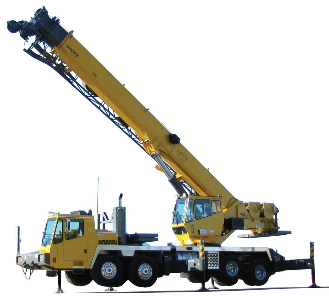
This manual provides important information for the operator of the TMS700E10 Series Grove Manitowoc Crane.
The mobile crane carrier incorporates an all welded steel frame. The 8x4x4 carrier utilizes two drive axles and two steer axles. Axle steering is provided by a power steering pump, gearbox and control valve. The engine is mounted in the front of the carrier and provides power through an 11 speed forward and 3 speed reverse manual transmission.
Hydraulic, single stage double box telescopic beams with inverted stabilizer (jack) cylinder outriggers are integral with the carrier frame. The outriggers are utilized in three positions; fully extended, intermediate (50%) extended, and fully retracted. The carrier is also equipped with a center front stabilizer that has a permanently mounted pad.
The superstructure is capable of 360° rotation in either direction. All crane functions, with the exception of counterweight removal, are controlled from the fullyenclosed cab mounted on the superstructure. The crane is equipped with a four-section boom. Additional reach is obtained by utilizing an optional swingaway boom extension. Lifting is provided by a main hoist and an optional auxiliary hoist. For basic crane component locations, (see Figure 1-1).
New Owner
If you are the new owner of a Manitowoc crane, please register it with Manitowoc Crane Care so we have the ability to contact you if the need arises. Go to: www.manitowoccranes.com/MCG_CARE/Includes/EN/ changeofownership.cfm and complete the form.
Item Description
1Folding Swingaway
2Boom
3Section 4
4Outrigger Stabilizer
5Removable Counterweight
6Auxiliary Hoist
7Main Hoist
8Boom Pivot
9Superstructure Cab
10Lift Cylinder
11Boom Rest
12Boom Nose Sheaves
Item Description
13Auxiliary Boom Nose
14Carrier Cab
15Center Front Stabilizer
16Front Axles
17Outrigger Beam
18Outrigger
19Hydraulic Oil Cooler
20Rear Tandem Axles
21Fuel Tank
22Outrigger Float
23Diesel Exhaust Fluid (DEF) Tank
24Fuel Filter, Primary
Section 2
SAFETY MESSAGES General
The importance of safe operation and maintenance cannot be overemphasized. Carelessness or neglect on the part of operators, job supervisors and planners, rigging personnel, and job site workers can result in their death or injury and costly damage to the crane and property.
To alert personnel to hazardous operating practices and maintenance procedures, safety messages are used throughout the manual. Each safety message contains a safety alert symbol and a signal word to identify the hazard’s degree of seriousness.
Safety Alert Symbol
This safety alert symbol means ATTENTION! Become alert - your safety is involved! Obey all safety messages that follow this symbol to avoid possible death or injury.
Signal Words
Danger
Identifies hazards that will result in death or serious injury if the message is ignored
WARNING
Identifies hazards that may result in death or serious injury if the message is ignored. CAUTION
Identifies hazards that could result in minor or moderate injury if the message is ignored.
Caution
Without the safety alert symbol, identifies hazards that could result in property damage if the message is ignored.
NOTE: Emphasizes operation or maintenance procedures.
General
It is impossible to compile a list of safety precautions covering all situations. However, there are basic principles that must be followed during your daily routine. Safety is your primary responsibility, since any piece of equipment is only as safe as the person at the controls
Read and follow the information located in Model Specific Information near the end of this section.
This information has been provided to assist in promoting a safe working atmosphere for yourself and those around you. It is not meant to cover every conceivable circumstance which could arise. It is intended to present basic safety precautions that should be followed in daily operation.
Because you are the only part of the crane that can think and reason, your responsibility is not lessened by the addition of operational aids or warning devices. Indeed, you must guard against acquiring a false sense of security when using them. They are there to assist, not direct the operation. Operational aids or warning devices can be mechanical, electrical, electronic, or a combination thereof. They are subject to failure or misuse and should not be relied upon in place of good operating practices.
You are the only one who can be relied upon to assure the safety of yourself and those around you. Be a professional and follow the rules of safety
Remember, failure to follow just one safety precaution could cause an accident that results in death or serious injury to personnel or damage to equipment. You are responsible for the safety of yourself and those around you.
Accidents
Following any accident or damage to equipment, the Manitowoc distributor must be immediately advised of the incident and consulted on necessary inspections and repairs. Should the distributor not be immediately available, contact should be made directly with Manitowoc Product Safety at the address below. The crane must not be returned to service until it is thoroughly inspected for any evidence of damage. All damaged parts must be repaired or replaced as authorized by your Manitowoc distributor and/or Manitowoc Crane Care.
If this crane becomes involved in a property damage and/or personal injury accident, immediately contact your Manitowoc distributor. If the distributor is unknown and/or cannot be reached, contact Product Safety at:
The Manitowoc Company, Inc.
1565 East Buchanan Trail Shady Grove, PA 17256-0021
Phone:888-777-3378 (888-PSR.DEPT)
Fax:717-593-5152
E-mail:product.safety@manitowoc.com
OPERATOR’S INFORMATION
You must read and understand this Operator’s Manual and the Load Chart before operating your new crane. You must also view and understand the supplied safety video. This manual and Load Chart must be readily available to the operator at all times and must remain in the cab (if equipped) or operator’s station while the crane is in use.
The Operator’s Manual supplied with and considered part of your crane must be read and completely understood by each person responsible for assembly, disassembly, operation and maintenance of the crane.
No personnel shall be allowed to climb onto the crane or enter the crane cab or operator’s station unless performance of their duties require them to do so, and then only with knowledge of the operator or other qualified person.
Allow No One other than the operator to be on the crane while the crane is operating or moving, unless they are seated in a two-man cab.
Refer to the Parts Manual for this crane for the locations of all safety decals.
You must be familiar with the regulations and standards governing cranes and their operation. Work practice requirements may vary slightly between government regulations, industry standards, and employer policies so a thorough knowledge of all such relevant work rules is necessary.
Do not remove the Load Chart, this Operator’s Manual, or any decal from this crane.
Inspect the crane every day (before the start of each shift). Ensure that routine maintenance and lubrication are being dutifully performed. Don’t operate a damaged or poorly maintained crane. You risk lives when operating faulty machinery - including your own.
If adjustments or repairs are necessary, the operator shall notify the next operator.
OPERATOR’S QUALIFICATIONS
Qualified person is defined as one who by reason of knowledge, training and experience is thoroughly familiar with crane operations and the hazards involved. Such a person shall meet the operator qualifications specified in Occupational Safety and Health Administration (OSHA) Regulations (United States Federal Law), in ASME B30.5 American National Standard, or in any other applicable federal, state or local laws.
Ensure that all personnel working around the crane are thoroughly familiar with safe operating practices. You must be thoroughly familiar with the location and content of all placards and decals on the crane. Decals provide important instructions and warnings and must be read prior to any operational or maintenance function.
An untrained operator subjects himself and others to death or serious injury.
You must not operate this machine unless:
• You have been trained in the safe operation of this machine.
• You read, understand, and follow the safety and operating recommendations contained in the manufacturer’s manuals, your employer’s work rules, and applicable government regulations.
• You are sure the machine has been inspected and maintained in accordance with the manufacturer’s manuals and is operating properly.
• You are sure that all safety signs, guards, and other safety features are in place and in proper condition.
Do not attempt to operate the crane unless you are trained and thoroughly fam iliar with all operati onal functions. Controls and design may vary from crane to crane; therefore, it is important that you have specific training on the particular crane you will be operating.
Training is ESSENTIAL for pro per crane oper ation. Never jeopardize your own well-being or that of others by attempting to operate a crane on which you have not been trained.
You must be mentally and physically fit to operate a crane. Never attempt to operate a crane while under the influence of medication, narcotics, or alcohol. Any type of drug could impair physical, visual and mental reactions, and capabilities.
As operator of this crane, you are granted the authority to stop and refuse to lift loads until safety is assured.
Operational Aids
Operational aids are accessories that provide information to facilitate operation of a crane or that take control of particular functions without action of the operator when a limiting condition is sensed, as stated in the latest revision of the ASME B30.5 standard. Examples of such devices include, but are not limited to, the following: anti-two-block device, rated capacity indicator, rated capacity limiter, boom angle or radius indicator, boom length indicator, crane level indicator, hoist drum rotation indicator, load indicator, and wind speed indicator.
Manitowoc remains committed to providing reliable products that enable users and operators to safely lift and position loads. Manitowoc has been an industry leader in the incorporation of operational aids into the design of its cranes. Federal law requires that cranes be properly maintained and kept in good working condition. The manuals that Manitowoc provides that are specific for each crane and the manufacturer’s manuals for the operational aids shall be followed. If an operational aid should fail to work properly, the crane user or owner must assure that repair or recalibration is accomplished as soon as is reasonably possible. If immediate repair or recalibration of an operational aid is not possible and there are exceptional circumstances which justify continued short-term use of the crane when operational aids are inoperative or malfunctioning, the following requirements shall apply for continued use or shutdown of the crane:
• Steps shall be taken to schedule repairs and recalibration immediately. The operational aids shall be put back into service as soon as replacement parts, if required, are available and the repairs and recalibration can be carried out. Every reasonable effort must be made to expedite repairs and recalibration.
• When a Load Indicator, Rated Capacity Indicator, or Rated Capacity Limiter is inoperative or malfunctioning, the designated person responsible for supervising the lifting operations shall establish procedures for determining load weights and shall ascertain that the weight of the load does not exceed the crane ratings at the radius where the load is to be handled.
• When a Boom Angle or Radius Indicator is inoperative or malfunctioning, the radius or boom angle shall be determined by measurement.
• When an Anti-Two-Blocking Device, Two-Blocking Damage Prevention Device or Two-Block Warning Device is inoperative or malfunctioning, the designated person responsible for supervising the lifting operations shall establish procedures, such as assigning an additional signal person to furnish equivalent protection. This does not apply when lifting personnel in load-line supported personnel platforms. Personnel shall not be lifted when anti-two-block devices are not functioning properly.
• When a Boom Length Indicator is inoperative or malfunctioning, the designated person responsible for supervising the lifting operations shall establish the boom lengths at which the lift will be made by actual measurements or marking on the boom.
• When a Level Indicator is inoperative or malfunctioning, other means shall be used to level the crane.
Rated Capacity Limiter (RCL) Systems (If Equipped)
Your crane may be equipped with an RCL system which is intended to aid the operator. An RCL is a device that automatically monitors radius, load weight, and load rating and prevents movements of the crane, which would result in an overload condition.
Test daily for proper operation. Never interfere with the proper functioning of operational aids or warning devices.
Under no condition should it be relied upon to replace the use of Load Charts and operating instructions. Sole reliance upon these electronic aids in place of good operating practices can cause an accident.
Know the weight of all loads and always check the capacity of the crane as shown on the Load Chart before making any lifts.
NEVER exceed the rated capacity shown on the Load Chart. Always check the Load Chart to ensure the load to be lifted at the desired radius is within the rated capacity of the crane. For detailed information concerning the operation and maintenance of the RCL system installed on the crane, see the RCL manufacturer’s manual supplied with the crane. Manufacturers of rated capacity limiters may refer to them in their manuals as a load moment indicator (LMI), a hydraulic capacity alert system (HCAS), a safe load indicator (SLI), or an EKS5; Manitowoc refers to these systems as a rated capacity limiter (RCL) throughout its Operator’s and Service Manuals.)
Anti-Two-Blocking Device
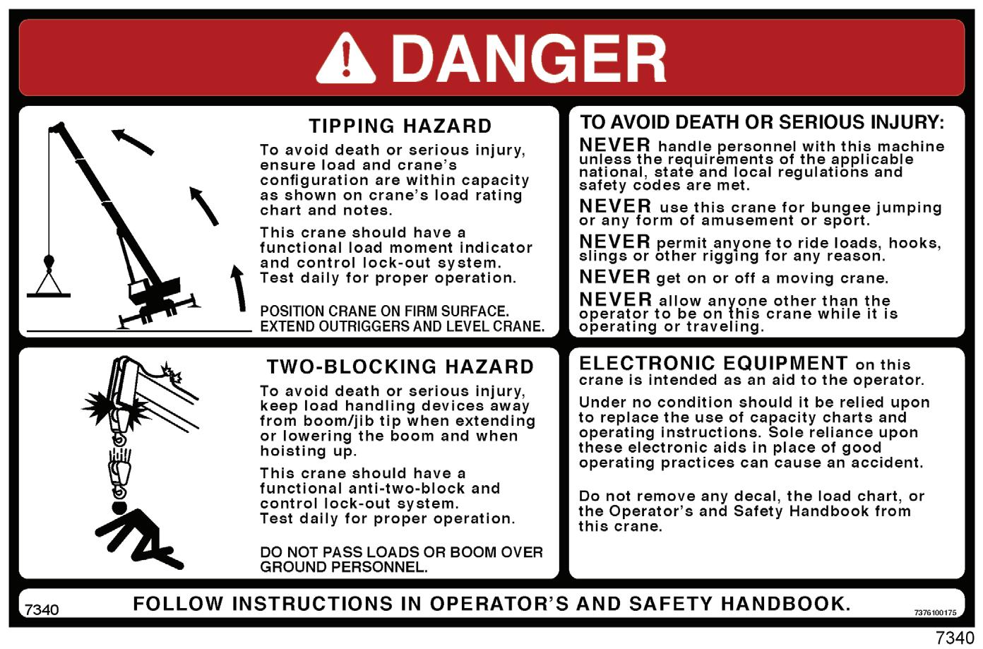
This crane should have a functional Anti-Two-Block and Control Lock-Out System. Test daily for proper operation.
Two-blocking occurs when the load block (hook block, headache ball, rigging, etc.) comes into physical contact with the boom (boom nose, sheaves, boom extension, etc.). Twoblocking can cause hoist lines (wire rope), rigging, reeving, and other components to become highly stressed and overloaded in which case the wire rope may fail allowing the load, block, etc. to free fall.
Two-blocking is more likely to occur when both the main and auxiliary hoist lines are reeved over the main boom nose and boom extension nose respectively. An operator, concentrating on the specific line being used, may telescope or lower the boom allowing the other hoist line attachment to contact the boom or boom extension nose, thus causing damage to the sheaves, or causing the wire rope to fail, dropping the lifting device to the ground and possibly injuring personnel working below.
Caution must be used when lowering the boom, extending the boom or hoisting up. Let out load line(s) simultaneously to prevent two-blocking the boom tip(s) and the hook block, etc. The closer the load is carried to the boom nose the more important it becomes to simultaneously let out wire rope as the boom is lowered. Keep load handling devices a minimum of 107cm (42in) below the boom nose at all times.
Two-blocking can be prevented. Operator awareness of the hazards of two-blocking is the most important factor in preventing this condition. An Anti-Two-Block System is intended to assist the operator in preventing dangerous twoblock conditions. It is not a replacement for operator awareness and competence.
Never interfere with the proper functioning of operational aids or warning devices.
Work Area Definition System (WADS) (If Equipped)
If your crane is equipped with a WADS, you must read and understand the manufacturer’s Operator’s Manual before operating the system. Become familiar with all proper operating procedures and with the identification of symbol usage.
The work area definition system is intended as an aid to the operator. It is not a substitute for safe crane operating practices, experience and good operator judgements.
CRANE STABILITY/STRUCTURAL STRENGTH
To avoid death or serious injury, ensure that the crane is on a firm surface with load and crane’s configuration within capacity as shown on the crane’s Load Chart and notes.
Ensure all pins and floats are properly installed and outrigger beams are properly extended before lifting on outriggers. On models equipped with outriggers that can be pinned at the mid-extend position (vertical stripe, if applicable), the outriggers must also be pinned when operating from the midextend position.
Use adequate cribbing under outrigger floats to distribute weight over a greater area. Check frequently for settling. Read and follow the following safety decal for cranes with center front stabilizers.
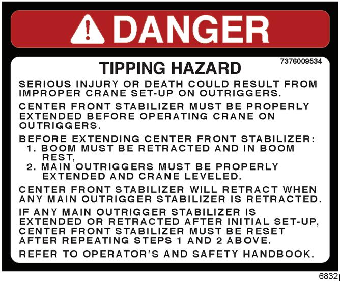
Carefully follow the procedures in this Operator’s Manual when extending or retracting the outriggers. Death or serious injury could result from improper crane setup on outriggers.
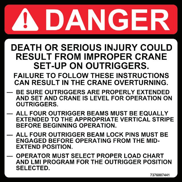
The operator must select the proper Load Chart and Rated Capacity Limiter (RCL) System program for the outrigger position selected.
Before swinging the superstructure over the side when the outriggers are retracted, check the Load Chart for backwards stability.
Long cantilever booms can create a tipping condition when in an extended and lowered position. Retract the boom proportionally with reference to the capacity of the applicable Load Chart
Check crane stability before lifting loads. Ensure the outriggers (or tires if lifting on rubber) are firmly positioned on solid surfaces. Ensure the crane is level, brakes are set, and the load is properly rigged and attached to the hook. Check the Load Chart against the weight of the load. Lift the load slightly off the ground and recheck the stability before proceeding with the lift. Determine the weight of the load before you attempt the lift.
Unless lifting within On Rubber capacities, outrigger beams and jack cylinders (plus center front stabilizer, if equipped) must be properly extended and set to provide precise leveling of the crane. Tires must be clear of the ground before lifting on outriggers.
KEEP THE BOOM SHORT. Swinging loads with a long line can create an unstable condition and possible structural failure of the boom.
Load Charts
Load Charts represent the absolute maximum allowable loads, which are based on either tipping or structural limitations of the crane under specific conditions. Knowing the precise load radius, boom length, and boom angle should be a part of your routine planning and operation. Actual loads, including necessary allowances, should be kept below the capacity shown on the applicable Load Chart Load Chart capacities are based on freely suspended loads. You must use the appropriate Load Chart when determining the capability of the crane in the configuration required to perform the lift.
Maximum lifting capacity is available at the shortest radius, minimum boom length, and highest boom angle.
Do not remove the Load Charts from the crane.
Work Site
Prior to any operation, you must inspect the entire work site, including ground conditions, where the crane will travel and operate. Be sure that the surfaces will support a load greater than the crane’s weight and maximum capacity.
Be aware of all conditions that could adversely affect the stability of the crane.
Wind Forces
Wind can have a significant affect on loads that may be lifted by a crane. Wind forces act differently on a crane depending upon the direction from which the wind is blowing (e.g., wind on the rear of the boom can result in decreased forward stability, wind on the underside of the boom can result in decreased backward stability, wind on the side of the boom can result in structural damages, etc.). To assist you in determining prevailing wind conditions, refer to Table 2-1.
Wind forces can exert extreme dynamic loads. Manitowoc recommends that a lift not be made if the wind can cause
Wind Force
Beaufort
Scale Designation
Wind Velocity km/h (mph) a loss of control in handling the load. Manitowoc recommends that, if the wind speed (velocity) is between 32km/h (20mph) to 48km/h (30mph), the load capacities shall be reduced to account for the size and shape of the load and the wind direction in relation to the machine for all boom and boom extension lengths. Further, operation of the crane in wind velocities over 48km/h (30mph) is not recommended.
Visible Indicator
Effects of wind as observed on land
Zero (0)Calm less than 1 (<1)Calm; smoke rises vertically
1Light Air1.1-5.5 (1-3)
2Light Breeze5.6-11 (4-7)
Smoke drift indicates wind direction. Leaves and wind vanes are stationary.
Wind felt on exposed skin. Leaves rustle. Wind vanes begin to move.
3Gentle Breeze12-19 (8-12)Leaves/small twigs constantly moving. Light flags extended.
4 Moderate Breeze 20-28 (13-17)Dust and loose paper raised. Small branches begin to move.
Reduce crane load ratings and operating parameters at 32 km/h (20 mph)
5Fresh Breeze29-38 (18-24) Branches of a moderate size move. Small trees in leaf begin to sway.
6Strong Breeze39-49 (25-30)
Large branches in motion. Whistling heard in overhead wires. Umbrella use becomes difficult. Empty plastic bins tip over.
Cease all craning operations at 48 km/h (30 mph); lower & retract boom
7Moderate Gale50-61 (31-38)Whole trees in motion. Effort needed to walk against the wind.
Lifting Operations
Before lifting, position the crane on a firm surface, properly extend and set the outriggers, and level the crane. Depending on the nature of the supporting surface, adequate cribbing may be required to obtain a larger bearing surface.
The crane is equipped with a bubble level that should be used to determine whether the crane is level. The load line can also be used to estimate the levelness of the crane by checking to be sure it is in-line with the center of the boom at all points on the swing circle.
If the boom extension, or auxiliary boom nose is to be used, ensure the electrical cable and the weight for the Anti-TwoBlock Switch are properly installed and the Rated Capacity Limiter (RCL) is programmed for the crane configuration. Refer to the RCL operator’s manual supplied with the crane.
Verify the crane’s capacity by checking the Load Chart against the weight of the load. Then, lift the load slightly at first to ensure stability before proceeding with the lift.
Be sure the load is properly rigged and attached. Always determine the weight of the load before you attempt to lift it and remember that all rigging (slings, etc.) and lifting devices (hook block, boom extension, etc.) must be considered part of the load.
Measure the load radius before making a lift and stay within approved lifting areas based on the range diagrams and working area diagrams on the crane’s Load Chart
Always keep the load as near to the crane and as close to the ground as possible.
Do not overload the crane by exceeding the capacities shown on the appropriate Load Chart . Death or serious injury could result from the crane tipping over or failing structurally from overload.
The crane can tip over or fail structurally if:
• The load and crane’s configuration is not within the capacity as shown on the applicable Load Chart and notes.
• The ground is soft and/or the surface conditions are poor.
• Outriggers are not properly extended and set. On models equipped with outriggers that can be pinned at the mid-extend position, the outriggers must also be pinned when operating from the mid-extend position.
• Cribbing under the outrigger pads is inadequate.
• The crane is improperly operated.
Do not rely on the crane’s tipping to determine your lifting capacity.
Be sure the hoist line is vertical before lifting. Do not subject the crane to side loading. A side load can tip the crane or cause it to fail structurally.
Load Chart capacities are based on freely suspended loads. Do not pull posts, pilings, or submerged articles. Be sure the load is not frozen or otherwise attached to the ground before lifting.
If you should encounter a tipping condition, immediately lower the load with the hoist line and retract or elevate the boom to decrease the load radius. Never lower or extend the boom; this will aggravate the condition.
Use tag lines whenever possib le to help control the movement of the load.
When lifting loads, the crane will lean toward the boom and the load will swing out, increasing the load radius. Ensure the crane’s capacity is not exceeded when this occurs.
Do not strike any obstruction with the boom. If the boom should accidentally contact an object, stop immediately. Inspect the boom. Remove the crane from service if the boom is damaged.
Never push or pull with the crane boom. Avoid sudden starts and stops when moving the load. The inertia and an increased load radius could tip the crane over or cause it to fail structurally.
Use only one hoist at a time when lifting loads. Always use enough parts-of-line to accommodate the load to be lifted. Lifting with too few parts-of-line can result in failure of the wire rope.
Counterweight
On cranes equipped with removable counterweights, ensure the appropriate counterweight sections are properly installed for the lift being considered.
Do not add material to the counterweight to increase capacity. United States Federal law prohibits modification or additions which affect the capacity or safe operation of the equipment without the manufacturer’s written approval. [29CFR 1926.1434]
Outrigger Lift Off
Regarding “lifting” of an outrigger pad during craning activities, be advised that the rated loads for these cranes, as indicated on the crane’s Load Chart, do not exceed 85% of the tipping load on outriggers as determined by SAE J765 OCT90 “Cranes Stability Test Code.” An outrigger pad may lift off the ground during operation of the crane within the capacity limits of the Load Chart, yet the crane will not have reached instability. The “balance point” for stability testing according to SAE and Manitowoc criteria is a condition of loading wherein the load moment acting to overturn the crane is equal to the maximum moment of the crane available to resist overturning. This balance point or point of instability for a crane does not depend on “lifting” of an outrigger but rather on comparison of the “opposing” load moments.
The occurrence of an outrigger lifting from the ground is often attributed to the natural flex in the crane’s frame. This may happen when lifting a load in certain configurations within the capacity limits of the Load Chart and is not necessarily an indication of an unstable condition.
Provided the crane is properly set up, the crane is in good working condition, that all operator’s aids are properly programmed, that the qualified crane operator adheres to the instructions found in the applicable Load Chart , Operator’s Manual and decals on the crane, the crane should not be unstable.
Multiple Crane Lifts
Multiple crane lifts are not recommended.
Any lift that requires more than one crane must be precisely planned and coordinated by a designated person. If it is necessary to perform a multi-crane lift, the operator shall be responsible for assuring that the following minimum safety precautions are taken:
• Secure the services of a designated person to direct the operation.
• Use one qualified signal person.
• Coordinate lifting plans with the operators, designated person, and signal person prior to beginning the lift.
• Maintain communication between all parties throughout the entire operation. If possible, provide approved radio equipment for voice communication between all parties engaged in the lift.
• Use outriggers on cranes so equipped.
• Calculate the amount of weight to be lifted by each crane and attach slings at the correct points for proper weight distribution.
• Ensure the load lines are directly over the attach points to avoid side loading and tran sfer of loading from one crane to the other.
• Do not travel. Lift only from a stationary position.
Electrocution Hazard
Thoroughly read, understand, and abide by all applicable federal, state, and local regulations regarding operation of cranes near electric power lines or equipment.
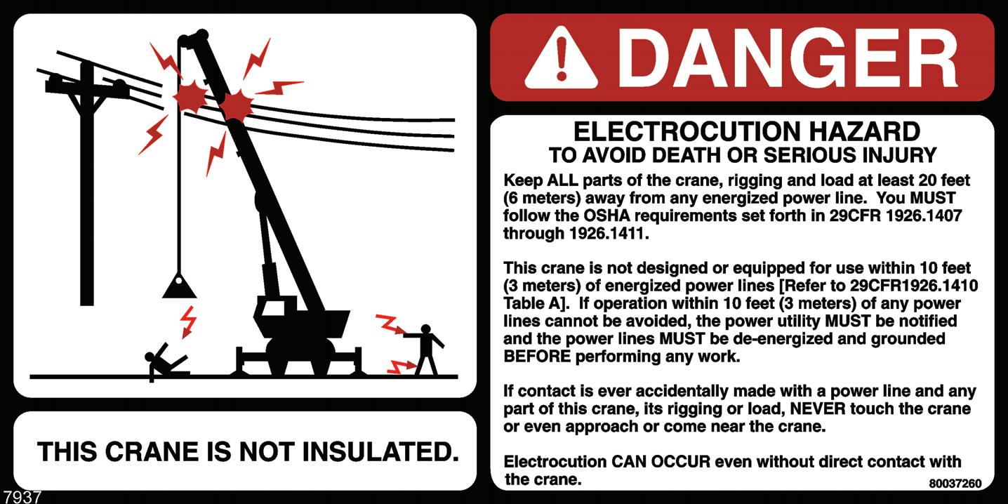
United States federal law prohibits the use of cranes closer than 6m (20ft) to power sources up to 350 kV and greater distances for higher voltages unless the line’s voltage is known [29CFR1910.180 and 29CFR1926.1400].
To avoid death or serious injury, Manitowoc recommends that all parts of crane, boom, and load be kept at least 6m (20ft) away from all electrical power lines and equipment less than 350 kV.
NOTE: For detailed guidelines on operating near power lines, refer to the current edition of OSHA
29CFR1926.1400 and ASME B30.5 American National Standard.
Warning
Electrocution Hazard!
Manitowoc cranes are not equipped with all features required to operate within OSHA 29CFR1926.1408, Table A clearances when the power lines are energized.
If operation within 3 meters (10 feet) of any power lines cannot be avoided, the power utility must be notified and the power lines must be de-energized and grounded before performing any work.
If contact is ever accidentally made with a power line and any part of this crane, its rigging or load, never touch the crane or even approach or come near the crane.
Electrocution can occur even without direct contact with the crane.
Crane operation is dangerous when close to an energized electrical power source. Exercise extreme caution and prudent judgement. Operate slowly and cautiously when in the vicinity of power lines.
Before operating this crane in the vicinity of electrical power lines or equipment, notify the power utility company. Obtain positive and absolute assurance that the power has been turned off.
This crane is not insulated. Always consider all parts of the load and the crane, including the wire rope, hoist cable, pendant cables, and tag lines, as conductors. You, the operator, are responsible for alerting all personnel of dangers associated with electrical power lines and equipment. Do not allow unnecessary personnel in the vicinity of the crane while operating. Permit no one to lean against or touch the crane. Permit no one, including riggers and load handlers, to hold the load, load lines, tag lines, or rigging gear.
If the load, wire rope, boom, or any portion of the crane contacts or comes too close to an electrical power source, everyone in, on, and around the crane can be seriously injured or killed.
Most overhead power lines are not insulated. Treat all overhead power lines as being energized unless you have reliable information to the contrary from the utility company or owner.
The rules in this Operator’s Manual must be followed at all times, even if the electrical power lines or equipment have been de-energized.
The safest way to avoid electrocution is to stay away from electrical power lines and electrical power sources.
It is not always necessary to contact a power line or power source to become electrocuted. Electricity, depending on magnitude, can arc or jump to any part of the load, load line, or crane boom if it comes too close to an electrical power source. Low voltages can also be dangerous.
Set-Up and Operation
During crane use, assume that every line is energized (“hot” or “live”) and take the necessary precautions.
Set up the crane in a position such that the load, boom, or any part of the crane and its attachments cannot be moved to within 6m (20ft) of electrical power lines or equipment. This includes the crane boom (fully extended to maximum height, radius, and length) and all attachments (boom extensions, rigging, loads, etc.). Overhead lines tend to blow in the wind so allow for lines’ moveme nt when determining safe operating distance.
A suitable barricade should be erected to physically restrain the crane and all attachments (including the load) from entering into an unsafe distance from electrical power lines or equipment.
Plan ahead and always plan a safe route before traveling under power lines. Rider poles should be erected on each side of a crossing to assure sufficient clearance is maintained.
United States OSHA regulations require a flagman when operating in close proximity to energized power lines.
Appoint a reliable and qualified signal person, equipped with a loud signal whistle or horn and voice communication equipment, to warn the operator when any part of the crane or load moves near a power source. This person should have no other duties while the crane is working.
Tag lines should always be made of non-conductive materials. Any tag line that is wet or dirty can conduct electricity.
Do not store materials under power lines or close to electrical power sources.
Electrocution Hazard Devices
The use of insulated links, insulated boom cages/guards, proximity warning devices, or mechanical limit stops does not assure that electrical contact will not occur. Even if codes or regulations require the use of such devices, failure to follow the rules listed here ma y result in serious injury or death. You should be aware that such devices have limitations and you should follow the rules and precautions outlined in this manual at all times even if the crane is equipped with these devices.
Insulating links installed into the load line afford limited protection from electrocution hazards. Links are limited in their lifting abilities, insula ting properties , and other properties that affect their performance. Moisture, dust, dirt, oils, and other contaminants can cause a link to conduct electricity. Due to their capacity ratings, some links are not effective for large cranes and/or high voltages/currents.
The only protection that may be afforded by an insulated link is below the link (electrically downstream), provided the link has been kept clean, free of contamination, has not been scratched or damaged, and is periodically tested (just before use) for its dielectric integrity.
Boom cages and boom guards afford limited protection from electrocution hazards. They are designed to cover only the boom nose and a small portion of the boom. Performance of boom cages and boom guards is limited by their physical size, insulating characteristics, and operating environment (e.g. dust, dirt, moisture, etc.). The insulating characteristics of these devices can be compromised if not kept clean, free of contamination, and undamaged.
Proximity sensing and warning devices are available in different types. Some use boom nose (localized) sensors and others use full boom length sensors. No warning may be given for components, cables, loads, and other attachments located outside of the sensing area. Much reliance is placed upon you, the operator, in selecting and properly setting the sensitivity of these devices.
Never rely solely on a device to protect you and your fellow workers from danger.
Some variables you must know and understand are:
• Proximity devices are advertised to detect the existence of electricity and not its quantity or magnitude.
• Some proximity devices may detect only alternating current (AC) and not direct current (DC).
• Some proximity devices detect radio frequency (RF) energy and others do not.
• Most proximity devices simply provide a signal (audible, visual, or both) for the operator; this signal must not be ignored.
• Sometimes the sensing portion of the proximity devices becomes confused by complex or differing arrays of power lines and power sources.
Do not depend on grounding. Grounding of a crane affords little or no protection from electrical hazards. The effectiveness of grounding is limited by the size of the conductor (wire) used, the condition of the ground, the magnitude of the voltage and current present, and numerous other factors.
Electrical Contact
If the crane should come in contact with an energized power source, you must:
1. Stay in the crane cab. Don’t panic
2. Immediately warn personnel in the vicinity to stay away.
3. Attempt to move the crane away from the contacted power source using the crane’s controls which are likely to remain functional.
4. Stay in the crane until the power company has been contacted and the power source has been de-energized. No one must attempt to come close to the crane or load until the power has been turned off.
Only as a last resort should an operator attempt to leave the crane upon contacting a power source. If it is absolutely necessary to leave the operator’s station, jump completely clear of the crane. Do not step off. Hop away with both feet together. Do not walk or run.
Following any contact with an energized electrical source, the Manitowoc distributor must be immediately advised of the incident and consulted on necessary inspections and repairs. Thoroughly inspect the wire rope and all points of contact on the crane. Should the distributor not be immediately available, contact Manitowoc Crane Care. The crane must not be returned to service until it is thoroughly inspected for any evidence of damage and all damaged parts are repaired or replaced as authorized by your Manitowoc distributor or Manitowoc Crane Care.
Special Operating Conditions and Equipment
Never operate the crane during an electrical thunderstorm. When operating near transmitter/communication towers where an electrical charge can be induced into the crane or load:
• The transmitter shall be deenergized OR,
• Tests shall be made to determine if an electrical charge will be induced into the crane or load.
• The crane must be provided an electrical ground.
• If taglines are used, they must be non-conductive.
• Every precaution must be taken to dissipate induced voltages. Consult a qualified RF (radio frequency) Consultant. Also refer to local, state, and federal codes and regulations.
When operating cranes equipped with electromagnets, you must take additional precautions. Permit no one to touch the magnet or load. Alert personnel by sounding a warning signal when moving a load. Do not allow the cover of the electromagnet power supply to be open during operation or at any time the electrical system is activated. Shut down the crane completely and open the magnet controls switch prior to connecting or disconnecting magnet leads. Use only a non-conductive device when positioning a load. Lower the magnet to the stowing area and shut off power before leaving the operator’s cab (if equipped) or operator’s station.
Personnel Handling
The American Society of Mechanical Engineers issued a new American National Standard entitled, Personnel Lifting Systems, ASME B30.23-2011:
This Volume establishes the design criteria, equipment characteristics, and operational procedures that are required when hoisting equipment within the scope of the ASME B30 Standard is used to lift personnel. Hoisting equipment defined by the
ASME 830 Standard is intended for material handling. It is not designed, manufactured, or intended to meet the standards for personnel handling equipment, such as ANSI/SIA A92 (Aerial Platforms). The equipment and implementation requirements listed in this Volume are not the same as that established for using equipment specifically designed and manufactured for lifting personnel. Hoisting equipment complying with the applicable Volumes of the ASME B30 Standard shall not be used to lift or lower personnel unless there are no less hazardous alternatives to providing access to the, area where work is to be performed. The lifting or lowering of personnel using ASME B30-compliant hoisting equipment is prohibited unless all applicable requirements of this volume have been met.
This new standard is consistent with the U.S. Department of Labor, Occupational Safety and Health Administration (OSHA) regulations for Construction that state, in 29CFRI926.1431:
General requirements. The use of a crane or derrick to hoist employees on a personnel platform is prohibited, except when the erection, use, and dismantling of conventional means of reaching the worksite, such as a personnel hoist, ladder, stairway, aerial lift, elevating work platform or scaffold, would be more hazardous or is not possible because of structural design or worksite conditions.
Additional requirements for crane operations are stated in ASME B30.5, Mobile And Locomotive Cranes, and in OSHA regulations 29CFRI910.180 for General Industry and 29CFRI926.1431 for Construction
Use of a Manitowoc crane to handle personnel is acceptable provided:
• The requirements of the applicable national, state and local regulations and safety codes are met.
• A determination has been made that use of a crane to handle personnel is the least hazardous means to perform the work.
• The crane operator shall be qualified to operate the specific type of hoisting equipment used in the personnel lift.
• The crane operator must remain at the crane controls at all times when personnel are off the ground.
• The crane operator and occupants have been instructed in the recognized hazards of personnel platform lifts.
• The crane is in proper working order.
• The crane must be equipped with a boom angle indicator that is visible to the crane operator.
• The crane's Load Chart is affixed at the operator’s station and readily accessible to the operator. The total weight of the loaded personnel platform and related rigging shall not exceed 50 percent of the rated capacity for the radius and configuration of the crane.
• The crane is level within one percent of level grade and located on a firm footing. Cranes with outriggers shall have them all deployed following manufacturer's specifications.
• The crane's Operator's Manual and other operating manuals are at the operator’s station and readily accessible to the operator.
• The platform meets the requirements as prescribed by applicable standards and regulations.
• For wire rope suspended platforms:
- The crane is equipped with a hook that can be closed and locked, eliminating the throat opening.
- The crane is equipped with a functional Anti-TwoBlock Device.
- The platform is properly attached and secured to the load hook.
• For boom mounted platforms:
- The platform is properly attached and secure.
To avoid death or serious injury:
• NEVER use this crane for bungee jumping or any form of amusement or sport.
• NEVER handle personnel on the loadline unless the requirements of applicable national, state and local regulations and safety codes are met.
• NEVER permit anyone to ride loads, hooks, slings or other rigging for any reason.
• NEVER get on or off a moving crane.
• NEVER allow anyone other than the operator to be on this crane while the machine is operating or traveling.
The following standards and regulations regarding personnel handling are available by mail at the following addresses:
• ASME (formerly ANSI) B30 Series American National Safety Standards For Cableways, Cranes, Derricks, Hoists, Hooks, Jacks, and Slings; ASME B30.5, Mobile And Locomotive Cranes, and ASME B30.23, Personnel Lifting Systems, are available by mail from the ASME, 22 Law Drive, Fairfield, New Jersey, 0700-2900
• US DOL/OSHA Rules and Regulations are available by mail from the Superintendent of Documents, PO Box 371954, Pittsburgh, PA, 15250-7954.
Environmental Protection
Dispose of waste properly! Improperly disposing of waste can threaten the environment.
Potentially harmful waste used in Manitowoc cranes includes — but is not limited to — oil, fuel, grease, coolant, air conditioning refrigerant, filters, batteries, and cloths which have come into contact with these environmentally harmful substances.
Handle and dispose of waste according to local, state, and federal environmental regulations.
When filling and draining crane components, observe the following:
• Do not pour waste fluids onto the ground, down any drain, or into any source of water.
• Always drain waste fluids into leak proof containers that are clearly marked with what they contain.
• Always fill or add fluids with a funnel or a filling pump.
• Immediately clean up any spills.
Maintenance
The crane must be inspected prior to use on each work shift. The owner, user, and operator must ensure that routine maintenance and lubrication are being dutifully performed. Never operate a damaged or poorly maintained crane.
Manitowoc continues to recommend that cranes be properly maintained, regularly inspected and repaired as necessary. Manitowoc reminds crane owners to ensure that all safety decals are in place and legible. Manitowoc continues to urge crane owners to upgrade their cranes with rated capacity limiter and control lever lockout systems for all lifting operations.
Shut down the crane while making repairs or adjustments. Always perform a function check after repairs have been made to ensure proper operation. Load tests should be performed when structural or lifting members are involved. Follow all applicable safety precautions in this manual when performing crane maintenance as well as crane operations. Keep the crane free of mud, dirt, and grease at all times. Dirty equipment introduces hazards, wears-out faster, and makes proper maintenance difficult. Cleaning solutions used should be non-flammable, non-toxic and appropriate for the job.
Routine maintenance and inspection of this crane must be performed by a qualified person(s) according to the recommendations in the Manitowoc Crane Care Maintenance and Inspection Manual . Any questions regarding procedures and specifications should be directed to your Manitowoc distributor.
Service and Repairs
Warning
Fall Hazard!
Working at elevated heights without using proper fall protection can result in severe injury or death. Always use proper fall protection as required by local, state or federal regulations.
Service and repairs to the crane must only be performed by a qualified person. All service and repairs must be performed in accordance with manufacturer’s recommendations, this manual, and the service manual for this machine. If there is any question regarding maintenance procedures or specifications, contact your Manitowoc distributor for assistance.
Qualified person is defined as one who by reason of knowledge, training and experience is thoroughly familiar with the crane’s operation and required maintenance as well as the hazards involved in performing these tasks.
Training and qualification of maintenance and repair personnel are crane owner’s responsibility.
Any modification, alteration, or change to a crane which affects its original design and is not authorized and approved by Manitowoc is strictly prohibited. All replacement parts must be Manitowoc approved. Such action invalidates all warranties and makes the owner/user liable for any resultant accidents.
Hydraulic Fluid:
• Do not use your hand or any part of your body to check for hydraulic fluid leaks when the engine is running or the hydraulic system is under pressure. Fluid in the hydraulic system can be under enough pressure that it will penetrate the skin, causing serious injury or death. Use a piece of cardboard, or piece of paper, to search for leaks. Wear gloves to protect your hands from spraying fluid.
• If any hydraulic fluid is injected into the skin, obtain medical attention immediately or gangrene may result.
• Do not attempt to repair or tighten any hydraulic hose or fitting while the engine is running, or when the hydraulic system is under pressure.
• Never disconnect any hydraulic lines unless the boom is fully lowered, the engine is shut off, and the hydraulic pressure is relieved. To relieve hydraulic pressure, stop the engine and move the hydraulic controls in both directions several times.
• Hot hydraulic fluid will cause severe burns. Wait for the fluid to cool before disconnecting any hydraulic lines.
• Hydraulic fluid can cause permanent eye injury. Wear appropriate eye protection.
Moving Parts:
• Do not place limbs near moving parts. Amputation of a body part may result. Turn off the engine and wait until the fan and belts stop moving before servicing crane.
• Pinch points, which result from relative motion between mechanical parts, are areas of the machine that can cause personal injury or death. Do not place limbs or your body in contact with pinch points either on or around the machine. Care must be taken to prevent motion between pinch points when performing maintenance and to avoid such areas when movement is possible.
• Do not allow persons to stand near extending or lowering outriggers. Foot crushing could occur
Before performing any maintenance, service or repairs on the crane:
• The boom should be fully retracted and lowered and the load placed on the ground.
• Do not get under a raised boom unless the boom is blocked up safely. Always block up the boom before doing any servicing that requires the boom to be raised.
• Stop the engine and disconnect the battery.
• Controls should be properly tagged. Never operate the crane if it is tagged-out nor attempt to do so until it is restored to proper operating condition and all tags have been removed by the person(s) who installed them.
After maintenance or repairs:
• Replace all guards and covers that have been removed.
• Remove all tags, connect the battery, and perform a function check of all operating controls.
• Consult with Manitowoc Crane Care to determine if load testing is required after a structural repair is performed.
Lubrication
The crane must be lubricated according to the manufacturer’s recommendations for lubrication points, time intervals, and types. Lubricate at more frequent intervals when working under severe conditions.
Exercise care when servicing the hydraulic system of the crane, as pressurized hydraulic oil can cause serious injury. The following precautions must be taken when servicing the hydraulic system:
• Follow the manufacturer’s recommendations when adding oil to the system. Mixing the wrong fluids could destroy seals, causing component failure.
• Be certain all lines, components, and fittings are tight before resuming operation.
Tires
Warning
Possible equipment damage and/or personal injury!
Driving the crane with a tire and split-rim assembly under inflated at 80% or less of its recommended pressure can cause the wheel and/or tire to fail. Per OSHA Standard 1910.177(f)(2), when a tire has been driven under inflated at 80% or less of its recommended pressure, it must first be completely deflated, removed from the axle, disassembled, and inspected before re-inflation.
Inspect the tires for nicks, cuts, embedded material, and abnormal wear.
Ensure all lug nuts are properly torqued.
Ensure pneumatic tires are inflated to the proper pressure (refer to the Load Chart ). When inflating tires, use a tire gauge, clip-on inflator, and extension hose which will permit standing clear of the tire while inflating.
Wire Rope
Use only the wire rope specified by Manitowoc as indicated on the crane’s Load Chart . Substitution of an alternate wire rope may require the use of a different permissible line pull and, therefore, require different reeving.
NOTE: Wire rope may be purchased by contacting Manitowoc Crane Care.
Always make daily inspections of the wire rope, keeping in mind that all wire rope will eventually deteriorate to a point where it is no longer usable. Refuse to work with worn or damaged wire rope. Wire rope shall be taken out of service when any of the following conditions exist:
• For rotation-resistant running ropes: more than two (2) broken wires in a length of rope equal to six (6) times the rope diameter, or more than four (4) broken wires in a length of rope equal to thirty (30) times the rope diameter.
• For running ropes other than rotation resistant: six (6) broken wires in one rope lay or three (3) broken wires in one strand.
• One valley break where the wire fractures between strands in a running rope is cause for removal.
• Abrasion of the rope resulting in wear of the individual outside wires of 1/3 of the original wire diameter.
• Any kinking, bird caging, crushing, corrosion, or other damage resulting in distortion of the rope structure.
• Rope that has been in contact with a live power line or has been used as a ground in an electric circuit (eg. welding) may have wires that are fused or annealed and must be removed from service.
• In standing ropes, more than three (3) breaks in one rope lay in sections beyond the end connection or more than two (2) broken wires at an end connection.
• Core deterioration, usually observed as a rapid reduction in rope diameter, is cause for immediate removal of the rope.
The following is a brief outlin e of the basic information required to safely use wire rope.
• Wire ropes wear out. The strength of a wire rope begins to decrease when the rope is put to use and continues to decrease with each use. Wire rope will fail if worn-out, overloaded, misused, damaged or improperly maintained.
• The nominal strength, sometimes called catalog strength, of a wire rope applies only to a new, unused rope.
• The nominal strength of a wire rope should be considered the straight line pull which will actually break a new unused rope. The nominal strength of a wire rope should never be used as its working load.
• Each type of fitting attached to a wire rope has a specific efficiency rating which can reduce the working load of the wire rope assembly or rope system.
• Never overload a wire rope. This means never use the wire rope where the load applied to it is greater than the working load determined by the rope manufacturer.
• Never “shock load” a wire rope. A sudden application of force or load can cause both visible external and internal damage. There is no practical way to estimate the force applied by shock loading a rope. The sudden release of a load can also damage a wire rope.
• Lubricant is applied to the wires and strands of a wire rope when it is manufactured. The lubricant is depleted when the rope is in service and should be replaced periodically. Refer to the Service Manual for more information.
• In the U.S.A., regular inspections of the wire rope and keeping of permanent records signed by a qualified person are required by OSHA for almost every wire rope application. The purpose of the inspection is to determine whether or not a wire rope may continue to be safely used on the application. Inspection criteria, including number and location of broken wires, wear and elongation, have been established by OSHA, ANSI,
ASME and similar organizations. See the Service Manual for inspection procedures.
When inspecting wire ropes and attachments, keep all parts of your body and clothing away from rotating hoist drums and all rotating sheaves. Never handle the wire rope with bare hands.
Some conditions that lead to problems in wire rope systems include:
- Sheaves that are too small, worn or corrugated cause damage to a wire rope.
- Broken wires mean a loss in strength.
- Kinks permanently damage a wire rope and must be avoided.
- Wire ropes are damaged by knots. Wire rope with knots must never be used.
- Environmental factors such as corrosive conditions and heat can damage a wire rope.
- Lack of lubrication can significantly shorten the useful life of a wire rope.
- Contact with electrical wires and resulting arcing will damage a wire rope.
• An inspection should include verification that none of the specified removal criteria for this usage are met by checking for such things as:
- Surface wear; nominal and unusual.
- Broken wires; number and location.
- Reduction in diameter.
- Rope stretch (elongation).
- Integrity of end attachments.
- Evidence of abuse or contact with another object.
- Heat damage.
- Corrosion.
NOTE: A more detailed wire rope inspection procedure is given in the Service Manual
• When a wire rope has been removed from service because it is no longer suitable for use, it must not be reused on another application.
When installing a new rope:
• Keep all parts of your body and clothing away from rotating hoist drums and all rotating sheaves.
• Never handle the wire rope with bare hands.
• Follow proper instructions for removing rope from a reel.
• Apply back tension to the storage/payoff reel of the new rope to insure tight, even spooling onto the hoist drum.
• Operate the new rope - first through several cycles at light load and then through several cycles at intermediate load to allow the rope to adjust to operating conditions.
When using a wedge socket:
• Always inspect socket, wedge, and pin for correct size and condition.
• Do not use parts that are damaged, cracked, or modified.
• Assemble the wedge socket with live end of rope aligned with the centerline of pin and assure proper length of tail (dead end) protrudes beyond the socket.
Sheaves
Inspect the boom nose and hook block sheaves for proper operation, excessive wear, and damage every 50 hours or weekly. Inoperable, damaged and/or worn sheaves cause rapid deterioration of wire rope.
Ensure sheaves carrying ropes that can be momentarily unloaded are equipped with close fitting guards or other devices to guide the rope back into the groove when the load is reapplied. Ensure sheaves in the lower load block are equipped with close fitting guards that will prevent the ropes from becoming fouled when the block is lying on the ground with loose ropes.
To attain maximum wire rope life and minimize hook block rotation, it is recommended that even numbers of parts-ofline be used in multiple-part reeving whenever possible.
The use of nylon (polyamide) sheaves, as compared with metallic sheaves, may change the replacement criteria of rotation-resistant wire rope.
NOTE: The use of cast nylon (polyamide) sheaves will substantially increase the service life of wire rope. However, conventional rope retirement criteria based only upon visible wire breaks may prove inadequate in predicting rope failure. The user of cast nylon sheaves is therefore cautioned that a retirement criteria should be established based upon the user’s experience and the demands of his application.
Batteries
Battery electrolyte must not be allowed to contact the skin or eyes. If this occurs, flush the contacted area with water and consult a doctor immediately.
When checking and maintaining batteries, exercise the following procedures and precautions:
• Wear safety glasses when servicing batteries.
• If equipped, disconnect battery with the battery disconnect switch before disconnecting the ground battery cable.
• Do not break a live circuit at the battery terminal. Disconnect the ground battery cable first when removing a battery and connect it last when installing a battery.
• Do not short across the battery posts to check charge. Short circuit, spark, or flame could cause battery explosion.
• Maintain battery electrolyte at the proper level. Check the electrolyte with a flashlight.
• If applicable to your crane, check battery test indicator on maintenance-free batteries.
• Check battery condition only with proper test equipment. Batteries shall not be charged except in an open, wellventilated area that is free of flame, smoking, sparks, and fire.
Engine
Fuel the crane only with the engine turned off. Do not smoke while fueling the crane. Do not store flammable materials on the crane.
Be familiar with the location and use of the nearest fire extinguisher.
Be careful when checking the engine coolant level. The fluid may be hot and under pressure. Shut down the engine and allow the radiator time to cool before removing the radiator cap.
Shut down the engine and disconnect the battery before performing maintenance. If unable to do so for the task required, keep hands clear of the engine fan and other moving parts while performing maintenance.
Be careful of hot surfaces and hot fluids when performing maintenance on or around the engine.
Do not use ether to start the engine on cranes equipped with intake manifold grid heaters.
Transporting The Crane
Before transporting the crane, check the suitability of the proposed route with regard to the crane height, width, length, and weight.
Check load limits of bridges on the travel route and ensure they are greater than the combined weight of the crane and transporting vehicle.
When loading or unloading the crane on a trailer or railroad car, use a ramp capable of supporting the weight of the crane.
Ensure the crane is adequately secured to the transporting vehicle.
Before transporting the crane on a road or highway, first check state and local restrictions and regulations.
When using hookblock tie downs, excessive loading can be applied by pulling the cable too tight, particularly when reeved with multiple part lines. When the cable is hooked into the hookblock tie down, the cable should be merely “snugged-up” with slack provided at the center line of sheave to anchor point. Care must be exercised anytime any crane function is being performed while the cable is hooked into the hookblock tie down. Do not draw cable taut.
Travel Operation
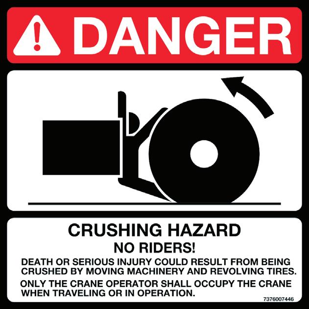
Only the crane operator shall occupy the crane when traveling.
When traveling, the boom should be completely retracted and lowered to the travel position and the turntable pin swing lock, if equipped, should be engaged. If equipped with boom rest, lower the boom into the boom rest and engage the turntable lock.
Strictly adhere to the guidelines and restrictions in the Load Chart for pick and carry operations.
This machine is manufactured with no axle suspension system. Traveling at high speeds, especially on rough ground, may create a bouncing affect that can result in loss of control. If bouncing occurs, reduce travel speed. (RT and Shuttlelift only)
Death or serious injury could result from being crushed by revolving tires.
Stunt driving and horse-play are strictly prohibited. Never allow anyone to hitch a ride or get on or off a moving crane.
Follow the instructions in this manual when preparing the crane for travel.
If using a boom dolly/trailer, thoroughly read and understand all the steps and safety precautions in this manual for setup and travel.
When driving the crane, ensure the cab is level, if equipped with a tilting cab.
Secure the hook block and other items before moving the crane.
Watch clearances when traveling. Do not take a chance of running into overhead or side obstructions.
When moving in tight quarters, post a signal person to help guard against collisions or bumping structures.
Before traveling a crane, check suitability of proposed route with regard to crane height, width, and length.
Never back up without the aid of a signal person to verify the area behind the crane is clear of obstructions and/or personnel.
On cranes equipped with air-operated brakes, do not attempt to move the crane until brake system air pressure is at operating level.
Check load limit of bridges. Before traveling across bridges, ensure they will carry a load greater than the crane’s weight.
If it is necessary to take the crane on a road or highway, check state and local restrictions and regulations.
Keep lights on, use traffic warning flags and signs, and use front and rear flag vehicles when necessary. Check state and local restrictions and regulations.
Always drive the crane carefully obeying speed limits and highway regulations.
Stay alert at the wheel.
If equipped, ensure that the hoist access platform hand rail and step are in the travel configuration.
Slopes:
- Pick and carry on level surfaces only.
- Refer to the Operation Section for more detailed information on traveling on slopes.
- Driving across a slope is dangerous, as unexpected changes in slope can cause tip over. Ascend or descend slopes slowly and with caution.
- When operating on a downhill slope, reduce travel speed and downshift to a low gear to permit compression braking by the engine and aid the application of the service brakes.
Work Practices
Personal Considerations
Always adjust the seat and lock it in position, and fasten the seat belt securely before you start the engine.
Do not wear loose clothing or jewelry that can get caught on controls or moving parts. Wear the protective clothing and personal safety gear issued or called for by the job conditions. Hard hat, safety shoes, ear protectors, reflective clothing, safety goggles, and heavy gloves may be required.
Crane Access
Warning
Fall Hazard!
Working at elevated heights without using proper fall protection can result in severe injury or death.
Always use proper fall protection as required by local, state or federal regulations.
You must take every precaution to ensure you do not slip and/or fall off the crane. Falling from any elevation could result in serious injury or death.
Never exit or enter the crane cab or deck by any other means than the access system(s) provided (i.e., steps and grab handles). Use the recommended hand-holds and steps to maintain a three-point contact when getting on or off the crane.
If necessary, use a ladder or aerial work platform to access the boom nose.
Do not make modifications or additions to the crane’s access system that have not been evaluated and approved by Manitowoc Crane Care.
Do not step on surfaces on the crane that are not approved or suitable for walking and working. All walking and working surfaces on the crane should be clean, dry, slip-resistant, and have adequate supporting capacity. Do not walk on a surface if slip-resistant material is missing or excessively worn.
Do not use the top of the boom as a walkway.
Do not step on the outrigger beams or outrigger pads (floats) to enter or exit the crane.
Use the hoist access platform (if equipped) when working in the hoist area.
Wear shoes with a highly slip-resistant sole material. Clean any mud or debris from shoes before entering the crane cab/ operator’s station or climbing onto the crane superstructure. Excessive dirt and debris on the hand-holds, access steps, or walking/working surfaces could cause a slipping accident. A shoe that is not clean might slip off a control pedal during operation.
Do not allow ground personnel to store their personal belongings (clothing, lunch boxes, water coolers, and the like) on the crane. This practice will prevent ground personnel from being crushed or electrocuted when they attempt to access personal belongings stored on the crane.
Job Preparation
Before crane use:
• Barricade the entire area where the crane is working and keep all unnecessary personnel out of the work area.
• Ensure that the crane is properly equipped including access steps, covers, doors, guards, and controls.
• Conduct a visual inspection for cracked welds, damaged components, loose pins/bolts, and wire connections. Any item or component that is found to be loose or damaged (broken, chipped, cracked, worn-through, etc.) must be repaired or replaced. Inspect for evidence of improper maintenance (consult your Service Manual).
• Check for proper functioning of all controls and operator aids (e.g. RCL).
• Check all braking (e.g. wheel, hoist, and swing brakes) and holding devices before operation.
You must ensure that the outriggers and stabilizers are properly extended and set before performing any lifting operations. On models equipped with outriggers that can be pinned at the mid-extend position, the outriggers must also be pinned when operating from the mid-extend position.
Clear all personnel from the outrigger area before extending or retracting the outriggers. Carefully follow the procedures in this Operator’s Manual when extending or retracting the outriggers. Death or serious injury could result from improper crane set up on outriggers.
Be familiar with surface co nditions and the presence of overhead obstructions and power lines.
Working
Operator shall be responsible for all operations under his/her direct control. When safety of an operation is in doubt, operator shall stop the crane’s functions in a controlled manner. Lift operations shall resume only after safety concerns have been addressed or the continuation of crane operations is directed by the lift supervisor.
Know the location and function of all machine controls.
Make sure all persons are away from the crane and the Travel Select Lever is in the “N” (Neutral) position with the parking brake engaged before starting the engine.
Sparks from the crane’s electrical system and/or engine exhaust can cause an explosion. Do not operate this crane in an area with flammable dust or vapors, unless good ventilation has removed the hazard.
Carbon monoxide fumes from the engine exhaust can cause suffocation in an enclosed area. Good ventilation is very important when operating the crane.
Before actuating swing or any other crane function, sound the horn and verify that all personnel are clear of rotating and moving parts.
Never operate the crane when darkness, fog, or other visibility restrictions make operation unsafe. Never operate a crane in thunderstorms or high winds.
Always be aware of your working environment during operation of the crane. Avoid contacting any part of the crane with external objects.
Clear all personnel from the counterweight and superstructure area before removing the counterweight.
Lifting
Keep unauthorized personnel clear of the working area during operation.
Only the crane operator shall occupy the crane when in operation.
You must always be aware of everything around the crane while lifting or traveling. If you are unable to clearly see in the direction of motion, you must post a look out or signal person before moving the crane or making a lift. Sound the horn to warn personnel
Operate the crane only from the operator’s seat. Do not reach in a window or door to operate any controls.
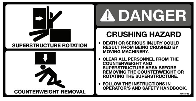
Operate the crane slowly and cautiously, looking carefully in the direction of movement.
A good practice is to make a “dry run” without a load before making the first lift. Become familiar with all factors peculiar to the job site.
Ensure the wire rope is properly routed on the hook block and boom nose and that all rope guards are in place.
Use enough parts of line for all lifts and check all lines, slings, and chains for correct attachment . To obtain maximum lifting capacities, the hook block must be set up with enough parts of line. Too few parts of line can result in failure of the wire rope or hoist. No less than three wraps of wire rope should remain on the hoist drum. When slings, ties, hooks, etc., are used, make certain they are correctly positioned and secured before raising or lowering the loads.
Be sure the rigging is adequate before lifting. Use tag lines when possible to position and restrain loads. Personnel using tag lines should be on the ground.
Be sure good rigging practices are being used. Refuse to use any poorly maintained or damaged equipment. Never wrap the hoist cable around a load.
If using a clam bucket, do not exceed 80% of the crane’s capacity.
Make certain the boom tip is centered directly over the load before lifting.
Ensure that all slings, ties, and hooks are correctly placed and secured before raising or lowering the load.
Be sure the load is well secured and attached to the hook with rigging of proper size and in good condition.
Check the hoist brake by raising the load a few inches, stopping the hoist and holding the load. Be sure the hoist brake is working correctly before continuing the lift.
When lowering a load always slow down the load’s descent before stopping the hoist. Do not attempt to change speeds on multiple-speed hoists while the hoist is in motion.
Watch the path of the boom and load when swinging. Avoid lowering or swinging the boom and load into ground personnel, equipment, or other objects.
Lift one load at a time. Do not lift two or more separately rigged loads at one time, even if the loads are within the crane’s rated capacity.
Never leave the crane with a load suspended. Should it become necessary to leave the crane, lower the load to the ground and stop the engine before leaving the operator’s station.
Remember, all rigging equipment must be considered as part of the load. Lifting capacities vary with working areas. If applicable, permissible working areas are listed in the Load Chart . When swinging from one working area to another, ensure Load Chart capacities are not exceeded. Know your crane!
Stop the hook block from swinging when unhooking a load. Swinging rapidly can cause the load to swing out and increase the load radius. Swing the load slowly. Swing with caution and keep the load lines vertical.
Look before swinging your crane. Even though the original setup may have been checked, situations do change.
Never swing or lower the boom into the carrier cab (if applicable).
Never push or pull loads with the crane’s boom; never drag a load.
Do not subject crane to side loading. A side load can tip the crane or cause it to fail structurally.
If the boom should contact an object, stop immediately and inspect the boom. Remove the crane from service if the boom is damaged.
When lifting a load the boom may deflect causing the load radius to increase—this condition is made worse when the boom is extended. Ensure weight of load is within crane’s capacity on Load Chart
Avoid sudden starts and stops when moving the load. The inertia and an increased load radius could tip the crane over or cause it to fail structurally.
Use tag lines (as appropriate) for positioning and restraining loads. Check the load slings before lifting.
Be sure everyone is clear of the crane and work area before making any lifts.
Never swing over personnel, regardless of whether load is suspended from or attached to the boom.
Hand Signals
A single qualified signal person shall be used at all times when:
• Working in the vicinity of power lines.
• The crane operator cannot clearly see the load at all times.
• Moving the crane in an area or direction in which the operator cannot clearly see the path of travel.
At all times use standardized hand signals - previously agreed upon and completely understood by the operator and signal person.
If communication with the signal person is lost, crane movement must be stopped until communications are restored.
Keep your attention focused on the crane’s operation. If for some reason you must look in another direction, stop all crane movement first.
Obey a signal to stop from anyone.
Boom Extension
To avoid death or serious injury, follow the procedures in this manual during erection, stowage, and use of the boom extension.
Install and secure all pins properly.
Control movement of boom extension at all times. Do not remove right side boom nose pins unless boom extension is properly pinned and secured on front and rear stowage brackets.
Danger
Boom Extension Hazard!
To avoid death or serious injury, follow procedures in Load
Chart , safety, and operation manuals during erection, stowage and use of boom extension. Install and secure all pins properly and control boom extension movement at all times.
Do not remove all the pins from both front and rear stowage brackets unless the boom extension is pinned to the right side of the boom nose.
Properly inspect, maintain, and adjust boom extension and mounting.
When assembling and disassembling boom extension sections, use blocking to adequately support each section and to provide proper alignment.
Stay outside of boom extension sections and lattice work. Watch for falling or flying pins when they are being removed.
Parking And Securing
Warning
Tipping Hazard!
When parking the crane and leaving it unattended follow the instructions in Section 3 of this manual.
Failure to comply with these instructions may cause death or serious injury
When parking on a grade, apply the parking brake and chock the wheels.
Section 3 of this manual provides instructions for parking and securing a crane when it is to be left unattended. These instructions are intended to allow the crane to be placed in the most stable and secure position. However, Manitowoc recognizes that certain jobsite conditions may not permit the boom and boom extension of a crane to be fully lowered to the ground. When a qualified person at a jobsite determines that it is not practical to lower the boom to the ground, we recommend the following additional instructions be followed:
• The crane should be left in the smallest, most stable, valid operational configuration that the job site practically allows.
• The crane can not be left running, with a load on the hook, or in erection mode, or in wind conditions in excess of allowed values.
• The boom should be retracted as far as is practical, the crane configured in as stable a configuration as possible (boom angle, superstructure orientation, boom extension angle, etc.)
• In high winds the boom and boom extensions should be lowered, or secured. Changing weather conditions including but not limited to : wind, ice accumulation, precipitation, flooding, lightning, etc. should be considered when determining the location and configuration of a crane when it is to be left unattended.
SHUT-DOWN
Use the following steps when shutting down the crane:
• Engage the parking brake.
• Fully retract and lower the boom.
• Engage the swing lock pin or 360 degree swing lock (if equipped).
• Place controls in neutral position.
• Shut down the engine and remove the ignition key.
• Chock the wheels, if not on outriggers.
• Lock the operator’s cab (if applicable) and install vandal guards, if used.
Cold Weather Operation
Cold weather operation requires additional caution on the part of the operator.
Check operating procedures in this manual for cold weather starting.
Don’t touch metal surfaces that could freeze you to them.
Clean the crane of all ice and snow.
Allow ample time for hydraulic oil to warm up.
In freezing weather, park the crane in an area where it cannot become frozen to the ground. The drive line can be damaged when attempting to free a frozen crane.
If applicable to your crane, frequently check all air tanks for water in freezing weather.
If applicable to your crane, always handle propane tanks according to the supplier’s instructions.
Never store flammable materials on the crane.
If cold weather starting aids are provided on your crane, use them. The use of aerosol spray or other types of starting fluids containing ether/volatiles can cause explosions or fire.
Temperature Effects On Hook Blocks
The following information applies to Gunnebo Johnston crane hook blocks:
“ Never use a crane block in extreme temperatures...Sudden failure can occur.
Crane blocks shall not be heated above 82°C (180°F). Craneblock Working Load Limit is valid between 82°C (180°F) and service temperature given on the identification tag with normal lifting precautions.
Additional lifting precautions are required below the service temperature given on the identification tag because cold temperature begins to affect the crane block material properties.
Lifting above 75% of the Working Load Limit (WLL), at temperatures between the service temperature given on the identification tag and -40°C (-40°F), must (be) done at a slow and steady rate to avoid stress spikes common in normal hoisting dynamics.
75% of the WLL must not be exceeded, when lifting in temperatures below -40°C (-40°F).”
Temperature Effects On Hydraulic Cylinders
Hydraulic oil expands when heated and contracts when cooled. This is a natural phenomena that happens to all liquids. The coefficient of expansion for API Group 1 hydraulic oil is approximately 0.00043 cubic inches per cubic inch of volume for 1°F of temperature change. Thermal contraction will allow a cylinder to retract as the hydraulic fluid which is trapped in the cylinder cools.
The change in the length of a cylinder is proportional to the extended length of the cylinder and to the change in temperature of the oil in the cylinder. For example, a cylinder extended 25ft in which the oil cools 60°F would retract approximately 7 3/4in (see Table 2-2). A cylinder extended 5 feet in which the oil cools 60°F would only retract approximately 1 1/2in. The rate at which the oil cools depends on many factors and will be more noticeable with a larger difference in oil temperature verses the ambient temperature.
Thermal contraction coupled with improper lubrication or improper wear pad adjustments may, under certain conditions, cause a “stick-slip” condition in the boom. This “stick-slip” condition could result in the load not moving smoothly. Proper boom lubrication and wear pad adjustment is important to permit the boom sections to slide freely. Slow movement of the boom may be undetected by the operator unless a load is suspended for a long period of time. To minimize the effects of thermal contraction or “Stick-slip” it is recommended that the telescope control lever is activated periodically in the extend posi tion to mitigate the effects of cooling oil.
If a load and the boom is allowed to remain stationary for a period of time and the ambient temperature is cooler than the trapped oil temperature, the trapped oil in the cylinders will cool. The load will lower as the telescope cylinder(s) retracts allowing the boom to come in. Also, the boom angle will decrease as the lift cylinder(s) retracts causing an increase in radius and a decrease in load height.
This situation will also occur in reverse. If a crane is set up in the morning with cool oil and the daytime ambient temperature heats the oil, the cylinders will extend in similar proportions.
Table 2-2 and Table 2-3 have been prepared to assist you in determining the approximate amount of retraction/extension that may be expected from a hydraulic cylinder as a result of change in the temperature of the hydraulic oil inside the cylinder. The chart is for dry rod cylinders. If the cylinder rod is filled with hydraulic oil, the contraction rate is somewhat greater.
NOTE: Operators and service personnel must be aware that load movement, as a result of this phenomena, can be easily mistaken as leaking cylinder seals or faulty holding valves. If leaking seals or faulty holding valves are suspected to be the problem, refer to Service Bulletin dealing with testing telescope cylinders. ( Service Bulletin 98-036 applies to TMS700 and Service Bulletin G06-005A applies to RT890 and RT9130.
Overload Inspection
This information supplements the Rated Capacity Limiter (RCL) manual supplied with each Grove crane. When the RCL system has acknowledged an overload on your crane, you must carry out specified inspections on the crane.
These inspections apply only to overloads up to 50%. For overloads of 50% or higher, crane operation must be stopped immediately and Crane Care must be contacted for corrective action.
Warning
Overload Hazard!
To avoid an accident caused by overload damage to your crane:
•Perform the inspections outlined in this publication for overloads up to 50%.
•Stop operating the crane and contact Manitowoc Crane Care immediately for overloads of 50% and higher.
NOTE:If your crane is equipped with CraneSTAR, an overload warning will be posted to the web site for review by the crane owner.
Overload warnings do NOT indicate real time events! Warnings could be sent 24 hours (or more) after the actual event.
Overload less than 25%
1 SheavesInspect all for damage.
2 Luffing Mechanism/ Cylinder Inspect for damage/leaks.
3 Collar-wear pads Inspect all for damage.
Overload from 25% to 49%
1 SheavesInspect all for damage.
2 Luffing Mechanism/ Cylinder Inspect for damage/leaks.
3 Collar-wear pads Inspect all for damage.
4 Collar-weldsInspect all for cracks.
5 Telescopic Sections Inspect for bent or twisted sections. Check the boom for straightness.
6 Lift Cylinder Head Area Inspect for bends or cracked welds.
7 Turret-Base Section Inspect for cracked welds.
8 Locking Area (Pin Booms) Inspect for elongated holes.
9 WeldsInspect for cracks.
10 Paint Inspect for cracked paint which could indicate twisted, stretched, or compressed members.
Overload less than 25%
1 Lift CylinderInspect for leaking.
2 Turntable Bearing Check bolts for proper torque.
3 Wire RopeInspect all for damage.
Overload from 25% to 49%
1 Lift CylinderInspect for leaking.
2 Turntable Bearing Check bolts for proper torque.
3 Wire RopeInspect all for damage.
4 Hoist/DrumsInspect each for damage.
5 Hoist BrakesBrakes must hold rated line pull.
6 Bearing Main Boom Pivot Pin Inspect for deformation, cracked welds.
7 Lift Cylinderlower mount Inspect pin and welds.
8 TurntableInspect for deformation, cracked welds.
9 WeldsInspect for cracks.
10 Paint Inspect for cracked paint which could indicate twisted, stretched, or compressed members.
See topic in Swing section of Service Manual.
See topic in Introduction section of Service Manual.
See topic in Swing section of Service Manual.
See topic in Introduction section of Service Manual.
Overload less than 25%
1 Stabilizer Cylinders Inspect for leaking.
2 Outrigger Pads Inspect for deformation and cracked welds.
Overload from 25% to 49%
1 Stabilizer Cylinders Inspect for leaking.
2 Outrigger Pads Inspect for deformation and cracked welds.
3 Outrigger Beams Inspect for deformation and cracked welds.
4 Outrigger Boxes Inspect for deformation and cracked welds.
5 WeldsInspect for cracks.
6 Paint Inspect for cracked paint which could indicate twisted, stretched, or compressed members.
Section 3
Operating Controls And Procedures
The crane is equipped with two cabs, a carrier cab and a superstructure cab. The carrier cab Figure3-1 contains all controls and indicators necessary for crane traveling and parking. The superstructure cab Figure3-3 contains all controls and indicators necessary to perform all craning operations. Both cabs utilize international symbols and English text to label the various controls. For detailed information on either cab, refer to either CARRIER CAB or SUPERSTRUCTURE CAB in this Section.
NOTE: The following paragraphs describe all the available (standard and optional—some machines may not be equipped with the optional controls shown) controls and indicators located in the cab. The numbers in () represent the index number from Figure3-1 through Figure3-3.
All rocker switches, except the engine diagnostics switches, contain one or two LED lighted slots in the switch for illumination. In addition, all but the hydraulic pump disconnect switch contains a LED lighted square to indicate when the switch/function is activated.
CARRIER CAB Engine Controls and Indicators Gauge Cluster
The gauge cluster (5) is located in the center of the front console assembly and contains a voltmeter, oil pressure gauge, water temperature gauge, and a fuel quantity gauge.
Voltmeter
The voltmeter (VOLTS) is located on the lower right of the gauge cluster. With the ignition switch in the RUN (1) position and before starting the engine, the voltmeter indicates the condition of the batteries. With the engine running, the voltmeter indicates output voltage of the alternator. The voltmeter scale is from 10 to 16 volts.
Engine Oil Pressure Gauge
The engine oil pressure (OIL) gauge is located on the upper right of the gauge cluster. The gauge indicates the engine oil pressure on a scale calibrated from zero (0) to 80 psi. It receives a signal from an oil pressure sending unit on the engine.
Water Temperature Gauge
The engine coolant temperature (TEMP) gauge is located on the lower left of the gauge cluster. The gauge indicates the engine coolant temperature on a scale calibrated from 100 to
240 ° F. The gauge receives a signal from a temperature sending unit in the engine cooling system.
Fuel Quantity Gauge
The fuel quantity (FUEL) gauge is located on the upper left of the gauge cluster. The gauge indicates the quantity of fuel in the tank and has a scale calibrated from empty (E) to full (F). The fuel quantity gauge receives a signal from a sending unit in the fuel tank.
Engine Stop Indicator
The engine stop indicator (23) is located at the top middle left of the front console. It lights red when energized by a signal from the engine ECM that signifies a serious engine problem that requires the vehicle and the engine to be stopped as soon as safely possible. Also a warning buzzer will sound. Besides alerting the operator of system faults, the engine stop light, along with the engine warning light, is used in the diagnostic work of the engine control system.
The diagnostic mode begins when the ignition switch and engine diagnostics test switch are on and the engine is not running. The amber light flashes at the beginning of a fault code sequence, the red light flashes the three-digit or fourdigit code for the active fault and the amber light flashes again to separate the previous red light sequence from the next one. Each code will be flashed twice before moving to the next code. When all codes have been flashed, the sequence will begin again. If no codes are present, both the engine warning and engine stop lights will remain on.
Engine Warning Indicator
The engine warning indicator (24) is located at the top middle left of the front console. It lights amber when energized by a signal from the engine ECM that gives the operator a signal that there is an engine problem which must be corrected. Besides alerting the operator of system faults, the engine warning light, along with the engine stop light, is used in diagnostic work of the engine control system.
The diagnostic mode begins when the ignition switch and engine diagnostics test switch are on and the engine is not running. The amber light flashes at the beginning of a fault code sequence, the red light flashes the three-digit or fourdigit code for the active fault and the amber light flashes again to separate the previous red light sequence from the next one. Each code will be flashed twice before moving to the next code. When all codes have been flashed, the sequence will begin again. If no codes are present, both the engine warning and engine stop lights will remain on.
Tachometer
The tachometer (2) is located on the left side of the front console. The tachometer is calibrated in RPM x 100 with a range of zero (0) to 35 and receives a signal from the sender unit on the engine.
Engine Brake Switches
The engine brake switches are located at the top of the right hand console. The two position (ON/OFF) switch (22) energizes the engine brake. When the switch is in the ON position, the amber LED in t he switch will be lit. The two position (HIGH/LOW) switch (20) controls the amount of engine braking. When the switch is in the HIGH position, the amber LED in the switch will be lit.
Ignition Switch
The ignition switch (14) is located on the right side of the front console. The switch is key operated with four positions: accessory (ACC) (3), OFF (0), RUN (1), and START (2). With ignition switches in both cabs in the OFF position, all electrical power is off except for the headlights, marker lights, gauge lights, turn and stop light, backup lights and alarm, carrier and superstructure cab dome lights, carrier and superstructure cab 12v accessory outlets, boom work lights, superstructure cab work lights, and superstructure horn. The ACC position energizes all electrical components except the engine ECM and starter circuit components. The RUN position is the same as ACC except the engine ECM is energized. The START position energizes the starter relay which in turn energizes the cranking motor solenoid and cranks the engine for starting. The switch will return to RUN when the switch is released after the engine is started. Turn the switch to OFF to shut down the engine.
Throttle Pedal
The throttle pedal (38) is the right most pedal on the cab floor. It is used to control engine RPM. The foot pedal is electronically connected to the engine and modulates engine speed proportionately to the foot pressure applied. The pedal is angled for increased operator comfort.
Engine Diagnostics Switches
Two engine diagnostics (35, 36) switches are located on the right side panel.
Engine Diagnostics/ Idle +/– Switch
This switch (35) is a three position (+/-) momentary rocker switch that provides idle-contr ol inputs that increase and decrease the engine idle speed (when test mode switch is in the OFF position) or diagnostic mode fault codes (when the test mode switch is in the ON position and engine is not running).
Engine Diagnostics Test Switch
This switch (36) is located on the right side console in the carrier cab. It enables the operator to turn on or off the engine diagnostic testing mode.
High Exhaust Temp Indicator
The high exhaust temp indicator (63) lights when an active exhaust regeneration has been initiated and the exhaust temperatures will be elevated above normal levels for the vehicle operating conditions This can occur while driving or during a manually initiated “stationary regeneration”.
Warning
While regenerating, ensure the exhaust is not aimed at any surface or material that will melt, burn, or explode.
Diesel Exhaust Fluid (DEF) Level Gauge
This gauge (10), located on the right center of the front control panel indicates the amount of fluid in the DEF tank. Engine performance will be derated per the following conditions:
• 3% derated during inducement
• 5% derated during the warning level of the fluid
• 10% derated when the fluid level is low.
Regen Needed/Inhibit Indicator
This dual lamp indicator (42) is located on the right side of the front console in the carrier cab.The upper lamp is used to indicate when the first level of exhaust regeneration is needed. The inhibit indicator is illuminated when regen inhibit switch has been activated.
Regen Initiate/Inhibit Switch
This switch (41), located on the right side of the front console in the carrier cab, is used to initiate or inhibit a stationary exhaust regeneration. The switch must be cycled on and off to initiate regeneration. The regen inhibit switch is a maintained ON switch, when selected to manually override the regen process.
The clutch and brake pedals must also be released. The engine will automatically change speed as needed. The cycle will take approximately 20 minutes.
If regeneration (active or stationary) is not desired, press the inhibit side (bottom) of the switch. The regeneration inhibit indicator should illuminate. When the switch is in the center position, the engine will perform an active regeneration as it requires and is able.
Travel Controls and Indicators
Dual Air Pressure Gauge
The dual air pressure gauge (1) is located on the left side of the front console. The gauge is a direct reading pressure gauge with two indicating pointers, red for the primary system and green for the secondary system. The gauge has a dual scale calibrated from 100 to 1000 kPa and 0 to 150psi. The gauge is connected to each air system separately through tubing.
Low Air Pressure Indicator
The low air pressure (AIR PRESSURE LOW) indicator (27) is located on the upper center of the front console above the steering wheel. The indicator is a red light that lights when the pressure in either or both air systems is below 72-84 psi (5-5.8 bar). The indicator is controlled by two pressure switches electrically connected in parallel. To determine which system pressure is low, observe the dual air pressure gauge. In addition to illuminating the air pressure low indicator, the pressure switches also energize a warning buzzer.
Speedometer
The speedometer (4) is located on the upper left side of the front console above the steering wheel. The speedometer indicates road speed in both km/h (kilometers per hour) and mph (miles per hour). There is an odometer located at the bottom of the speedometer that shows total distance traveled.
Parking Brake Control
NOTE: The park brake must be set before the outrigger controls will operate.
The parking brake control (12) is located on the right side of the front console. The control is a push-pull type air valve used to apply and release the parking brakes on all four rear wheels.
Park Brake On Indicator
The park brake on indicator (29) is located at the top of the front console on the right side above the steering wheel. The indicator is a red light that lights when the crane parking brakes are applied. It is energized by a pressure switch on the parking brake valve. The pressure switch also controls the outrigger enable relay that permits operation of the outriggers.
Cross-Axle Differential Locked Indicator
The cross-axle differential locked (CROSS AXLE LOCKED) indicator (26) is located at the top of the front console above the steering column. The amber indicator lights to show that the cross axle differential is locked.
Caution
Do not operate the cross axle differential lock or the interaxle differential lock on dry roads.
Cross-Axle Differential Lock Control
The cross-axle differential lock control (17) is located on the lower left side of the front console and is used to lock the right and left wheels in a tandem set. The cross-axle differential lock increases tracti on on slippery roads. It is a two position lock/unlock lever actuated air valve.
Caution
Do not operate cross-axle differential lock while crane wheels are spinning or at speeds over approximately 16 km/h (10 mph). Release the throttle when locking or unlocking.
Inter-Axle Differential Lock Control
The inter-axle differential control (15) is located on the lower right side of the front console. In the LOCK position, both rear axles are locked together and turning at the same speed. In the UNLOCKED position, the axles operate independently of each other. The control is a lever actuated air valve.
Caution
Do not operate inter-axle differential lock while crane wheels are spinning or at speeds over approximately 16 km/h (10 mph). Release the throttle when locking or unlocking.
Inter-Axle DIfferential Lock Control Indicator
The inter-axle differential locked control indicator (inter- axle locked) (32) is located on the right side of the front console panel at the top. The amber indicator lights when the interaxle differential lock is engaged.
Brake Pedal
The brake pedal (37) is located on the cab floor, to the left of the foot throttle and is used to apply the service brakes.
Clutch Pedal
The clutch pedal (52) is located on the left side of the cab floor. It is used to engage or disengage the clutch for starting and stopping the vehicle.
Transmission Shift Lever
The transmission shift lever (40) is located on the right side of the cab. It is used to select the transmission gears.
Transmission Range Control Switch
The transmission range control switch (39) is located on the shift lever knob. It provides for high and low range shifting.
Transmission Deep Reduction Switch
The transmission deep reduction switch (59) is an air solenoid valve which can position the transmission for deep reduction. Pushing switch forward engages deep reduction, pulling switch backward disengages deep reduction. Operate only when machine is standing still.
Trailing Boom Trailer Emergency Brake Control (Optional)
The trailing boom (TRAILER EMERGENCY) brake control (11) is a push-pull type air valve located on the right side of the front console. The control is used to set and release the brakes on the trailing boom trailer.
Suspension Control
The suspension control (34) is a lever operated air valve located on the right side console. When positioned to INFLATE, the suspension air bags are inflated. When positioned to DEFLATE, the suspension air bags are deflated.
NOTE: The suspension air bags should be inflated at all times except when on outriggers or in a pick and carry mode.
Suspension Deflated Indicator
The suspension deflated indicator (33) is located on the right side console above the suspension control lever. The amber indicator lights when the air is removed from the suspension air bags. It is controlled by four pressure switches connected in series.
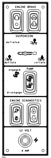
ItemDescription
1Dual Air Pressure Gauge
2Tachometer
3Left Turn Signal Indicator
4Speedometer
5Gauge Cluster (Fuel, Temperature, Oil, Volts)
6Right Turn Signal Indicator
7Heater Air Temperature Control
8Heater Fan Switch
912 Volt Accessory Outlet
10DEF Fluid Level Gauge
11Trailing Boom Trailer Emergency Brake Control
12Parking Brake Control
13Windshield Wiper/Washer Switch
14Ignition Switch
15Inter-Axle Differential Lock Control
16High Exhaust Temperature Indicator
17Cross-Axle Differential Lock Control
18Tire Inflator Control Switch
19Beacon Light Switch
20Engine Brake High/Low Switch
21Headlights Switch
22Engine Brake On/Off Switch
23Engine Stop Indicator
24Engine Warning Indicator
25Not Used
26Cross-Axle Differential Locked Indicator
27Air Pressure Low Indicator
28High Beam Indicator
29Park Brake On Indicator
30Swing Brake On Indicator
31Tire Inflator On Indicator
32Inter-Axle Differential Locked Indicator
33Suspension Deflated Indicator
34Suspension Control
35Engine Diagnostics/Idle Switch
36Engine Diagnostics Test
37Brake Pedal
Item Description
38Throttle Pedal
39Transmission Range Control Switch
40Transmission Shift Lever
41Regen Initiate/Inhibit Switch
42Regen Needed/Inhibit Indicator
43Fire Extinguisher
44Cab Dome Light
45Steering Wheel
46Horn Button
47Headlight Dimmer/Turn Signal Lever
48Windshield Wiper
49Air Conditioner Switch
50Cab Circulating Fan
51Not Used
52Clutch Pedal
53Not Used
54Circuit Breaker and Relay Panel
55Hazard Light Switch
56Steering Column Tilt/Telescope Lever
57Hydraulic Pump Engaged Indicator
58Hydraulic Pump Switch
59Transmission Deep Reduction Switch
60Seat Adjustment Lever
61Seat Tilt Lever
Swing Brake On Indicator (Optional)
The swing brake on indicator (30) is located at the top of the front console. The red indicator lights to warn the operator that the swing brake release pressure is not enough to hold the swing brake disengaged during trailing boom operation. In addition to illuminating the swing brake on indicator, the pressure switch also energizes a warning buzzer.
Hydraulic Pump Engaged Indicator
The pump engaged indicator (57) is located on the right side console. The amber indicator lights when the hydraulic pumps are engaged.
Hydraulic Pump Switch
The hydraulic pump switch (58) is located on the right side console. Putting the switch at ENGAGE energizes the PTO clutch solenoid to engage the transmission PTO that drives the main hydraulic pumps. A pressure switch senses when the pump is engaged and sends a signal to the engine ECM to limit engine speed to 1800 RPM on QSM machines and 1600 RPM on ISX machines.
Accessory Controls and Indicators
High Beam Indicator
The headlight high beam indicator (28) is located at the top of the center front console. The indicator is a blue light that lights when the headlights are on high beam.
Heater Air Temperature Control
The heater air temperature control (7) is located on the right side of the front console. The control is a rotary thermostat that opens and closes the valve in the hot water supply line to the heater.
Fan Switch
The fan switch (8) is located on the right side of the front console. This rotary switch controls the speed of the fan (LOW, MED, and HI) which in turn regulates the volume of air output. The far left position is OFF. The next two positions at 90° increments are LOW and medium (MED). The far right position is high (HI).
Air Conditioner Switch
The air conditioner switch (49) turns on the air conditioner when the fan switch is in an on position.
Windshield Wiper/Washer Switch
The windshield wiper/washer switch (13) is located on the right side of the front console. The switch has three positions; off, low, and high range. Rotating the switch energizes the wiper motor on the windshield washer pump assembly. Rotating the switch to the first detent energizes the wiper motor at low speed and rotating it to the second detent energizes the motor at high speed. Rotating the switch counterclockwise to off stops the motor and returns the wiper blade to the parked position. Push in on the switch to spray washing fluid on the windshield.
Headlights Switch
The headlights switch (21) is located on the left side of the front console. The switch is a push-pull type switch with a rheostat control. Pull the switch to the first detent to light the marker and gauge lights. Pull the switch to the second detent to light the headlights, marker lights and the gauge lights. Rotating the switch knob controls the brightness of the gauge lights.
Beacon Light Switch (Optional)
The beacon light switch (BEACON) (19) is a two position, ON-OFF rocker switch located on the left side of the front console that controls the beacon light on the top of the carrier cab. When the switch is in the ON position, the amber LED in the switch will be lit.
Headlights Dimmer Switch
The headlight dimmer switch (47) is incorporated in the turn signal switch. It is located on the left side of the steering column. The switch is activated by pulling or pushing the turn signal lever(s) toward you or away from you.
Turn Signal Lever
The turn signal lever (47) is located on the steering column. Positioning the lever down causes the indicator light on the column and the left front and left rear signals to flash. Positioning the lever up causes the indicator light on the column and the right front and right rear signals to flash.
Hazard Light Switch
The hazard light switch (55) is located on the steering column. Pushing forward on the switch (in the direction of the arrow) causes all the turn signals and the turn signal indicator lights on the column to flash.
Left Turn Signal Indicator
The left turn signal indicator (3) is located on the top left side of the front console. It is a green indicator light that flashes when the turn signal lever is pulled down or the hazard light switch is on.
Right Turn SIgnal Indicator
The right turn signal indicator (6) is located on the top right side of the front console. It is a green indicator light that flashes when the turn signal lever is pushed up or the hazard light switch is on.
Steering Column Tilt/Telescope Lever
The steering column tilt/telescope lever (56) is located on the steering column behind the turn signal lever. Pulling back on the lever allows the steering column to be tilted, and pushing forward on the lever allows the steering column to be telescoped in and out.
Horn Button
The horn button (46) is located in the center of the steering wheel (45). Depressing the horn button energizes the circuit sounding the horn.
Published3-13-2013, Control # 433-01
Fire Extinguisher
The fire extinguisher (43) is mounted on the inside rear of the cab.
Cab Circulating Fan
The cab circulating fan (50) is mounted on the left front of the cab and is controlled by a two speed switch on the base of the fan.
Seat Adjustment Lever
The seat adjustment lever (60) works by lifting on the bar at the front center of the seat.
Seat Tilt Lever
The seat tilt lever (61) operates by lifting the handle to tilt the backrest forward or backward.
Tire Inflator Switch
The tire inflation (TIRE INFLATOR) switch (18) is located on the left side of the front console. It is a guarded two position toggle air valve that activates the tire inflation system.
Tire Inflator On Indicator
The tire inflator on indicator (31) is located at the top of the front console. It is an amber light that is lit when the pressure switch in the tire inflation system is activated. In addition to illuminating the tire inflator on indicator, the pressure switch also energizes a warning buzzer.
12 VDC Accessory Outlet
The 12 vdc accessory outlet (9) is located on the right side console. It provides an outlet for the operator to plug in a 12 vdc accessory. It is protected by a 10 amp fuse.
Cab Dome Light
The cab dome light (44) is located in the center of the cab roof directly over the seat. It is controlled by a switch on the light and by a door switch that powers the light when the cab door is opened.
Air Horn (Not Shown)
A set of air horns are mounted on top of the cab and are controlled by a valve manually actuated by a cable inside the cab.
Fuse and Relay Panel
The fuse and relay panel (54) is located on the rear of the cab under a removable cover. It contains fuses and relays that protect and control the various electrical components of the carrier.
Additional Carrier Controls and Indicators
NOTE: The following paragraphs describe the additional controls and indicators located on the carrier to operate the outriggers. The numbers in parentheses () represent the index number from Figure3-2.
Outrigger Control Summary
There is an outrigger control box located on each side of the crane carrier. Each box contains an outrigger control panel with switches for extending and retracting the outrigger beams and for raising and lowering the outrigger stabilizer (jack) cylinders on that side of the crane. Each control panel also contains a control switch for raising and lowering the center front stabilizer. A level is installed at the bottom of the outrigger box. The following paragraphs explain these controls.
Item Description
1Outrigger Control Panel
2Outrigger Beam Selector Switch
3Extend/Retract Switch
4Center Front Stabilizer Switch
5Stabilizer Selector Switch
6Level Indicator
Outrigger Control Panel
There is one outrigger control panel (1) on each side of the unit’s frame. The panel on the right side operates the outrigger beams for that side only. The panel on the left side operates the outrigger beams for that side only. The stabilizers may be operated from the left or right side of the crane.
Outrigger Beam Selector Switch
The outrigger beam selector switch (2) is used to indicate desired operation of the front or rear outrigger beam for the side of the crane the control panel is on.
Extend/Retract Switch
The extend/retract switch (3) will operate both the outrigger beams or the stabilizers. After positioning the desired selector switch, positionin g the extend/retract switch energizes the control solenoid to allow hydraulic fluid to flow through the control solenoid valve and the individual solenoid valve and move the selected component in the desired direction. In addition , when the switch is positioned to either position, a signal is sent to the engine ECM to increase engine speed above idle for operation of the outriggers.
Center Front Stabilizer Switch
The center front stabilizer switch (4) is located in the center of the outrigger control panel. It must be used in conjunction with the extend/retract switch to control the operation of the center front stabilizer. The center front stabilizer will retract automatically when any of the other four stabilizers are retracted, therefore it must be reset if lifting is to be continued.
Stabilizer Selector Switch
The stabilizer selector switch (5) is used to choose which stabilizer to operate.
Level Indicator
The level indicator (6) is used to indicate when the crane is level during the positioning of the stabilizers.
Published3-13-2013, Control # 433-01
Daytime Running Lights
The daytime running lights are powered by the carrier ignition switch (14) accessory circuit Figure3-1. When the park brake control (29) is pulled to apply the park brake, the daytime running lights lose power and turn off. This feature allows the low beam of the headlights to automatically be on any time the crane is roading.
Superstructure Cab
The front console is laid out vertically and is located in the right front of the superstructure cab. This location provides the operator with a clear view out of the front of the cab. Additional indicators and switches are on the overhead console above the right side cab window. The outrigger controls are located on a hand held control box that is stored in a pocket on the left front of the superstructure cab.
NOTE: The following paragraphs describe all the available (standard and optional; some cranes may not be equipped with the optional controls shown) controls and indicators located in the cab. The numbers in () represent the index number from Figure3-3.
All rocker switches contain one or two LED lighted slots in the switch for illumination. In addition, all but the throttle mode switch contains a LED lighted square to indicate when the switch/function is activated.
Engine Controls and Indicators Hand Throttle Switch (Engine Increment/Decrement Switch)
This switch (31), located on the front console, is used to set the engine operating speed. It is a two position (+/-) momentary switch.
Pushing the top of the switch quickly increases (+) engine RPM to the maximum allowed operating speed. Pushing the bottom of the switch quickly decreases (-) engine RPM to idle speed (ISX engine only). Pushing and holding either side of the switch will increase or decrease engine speed. Releasing the switch will hold the engine at the current speed. Pressing the foot pedal will increase engine speed above the “hold” speed. Releasing the foot pedal causes the engine to return to the “hold” speed.
Gauge Cluster
The gauge cluster (29) is located in the center of the front console above the RCL panel and contains a voltmeter, oil pressure gauge, water temperature gauge, and a fuel quantity gauge.
Voltmeter
The voltmeter (VOLTS) is located on the lower right of the gauge cluster. With the ignition switch in the RUN (1) position and before starting the engine, the voltmeter indicates the condition of the batteries. With the engine running, the voltmeter indicates output voltage of the alternator. The voltmeter scale is from 10 to 16 volts.
Engine Oil Pressure Gauge
The engine oil pressure (OIL) gauge is located on the upper right of the gauge cluster. The gauge indicates the engine oil pressure on a scale calibrated from zero (0) to 80 psi. It receives a signal from an oil pressure sending unit on the engine.
Water Temperature Gauge
The engine coolant temperature (TEMP) gauge is located on the lower left of the gauge cluster. The gauge indicates the engine coolant temperature on a scale calibrated from 100 to 240 ° F. The gauge receives a signal from a temperature sending unit in the engine cooling system.
Fuel Quantity Gauge
The fuel quantity (FUEL) gauge is located on the upper left of the gauge cluster. The gauge indicates the quantity of fuel in the tank and has a scale calibrated from empty (E) to full (F). The fuel quantity gauge receives a signal from a sending unit in the fuel tank.
Ignition Switch
The ignition switch (32) is located on the front console. It is a key operated switch with four positions; 3 (accessory), 0 (off), 1 (run), and 2 (start). The switch is spring returned from the 2 position to the 1 position. In the 0 position, all electrical power in the superstructure is off except for the boom work lights, cab work lights, panel lights, dome light, swing horn, and accessory outlet. In the 3 position, all electrical components are energized except the starter circuit components. Placing the switch in the 2 position energizes the starter motor relay and solenoid for starting the engine. Releasing the switch will allow it to spring return to the 1 position. To shut down the engine, turn the switch to the 0 position.
Tachometer
The tachometer (TACH) (27) is located at the top of the front console and registers engine RPM. The tachometer is calibrated in rpm x 100 with a range of zero (0) to 35. The tachometer receives an electrical signal from a sending unit on the engine that does not use the machine’s electrical system.
Hourmeter
The hourmeter (28) is located at the bottom of the tachometer and registers the total hours that the engine has run. The hourmeter receives an electrical signal from the tachometer.