37 minute read
OPERATING CONTROLS AND PROCEDURESTMS500E OPERATOR’S MANUAL


Beacon Light (Optional)
The beacon light (13) is located on the left rear corner of the cab roof. It is operational anytime the ignition switch is in the ACC or RUN position.
12 VDC Accessory Outlet
The 12 VOLT accessory outlet (35) is located at the bottom of the front console. It provides an outlet for the operator to plug in a 12 vdc accessory. It is protected by a 10 amp fuse.
Fuse Panel
The fuse panel (12) is located under the cover panel on the back wall of the cab behind the seat. It contains 20 fuses that protect the various electrical components of the superstructure.
Published 07-05-07, Control # 098-03
Operational Procedures
Breaking-In A New Carrier
Your new Grove Manitowoc carrier has been thoroughly tested, adjusted, lubricated, and inspected prior to delivery. However, as road shock and crane operation occur, moving parts wear in, or gasket and hose connections take seat, an occasional oil, air, or coolant leak may develop. Immediate corrective action should be taken to avoid major repairs later. For detailed engine break-in, refer to the applicable engine manual.
The guidelines below will aid in getting a long service life out of the crane.
1. Operate as much as possible in the half to threequarters throttle or load range.
2. Avoid long periods of operation with the engine at idle or continuous maximum horsepower levels.
3. Observe instruments often and shut down at the first indication of an abnormal reading.
4. Operate to a power requirement that allows acceleration to governed speed when conditions require more power.
5. Check all components frequently for proper operation, unusual noises, and excessive heating.
6. Check the engine oil and coolant levels frequently. These guidelines should not be considered limitations but rather as a guide for familiarization of the machine and development of good operating habits.
Pre-Starting Checks
A complete walk-around visual inspection of the crane should always be made with special attention to structural damage, loose equipment, leaks, or other conditions that would require immediate correction for safe operation (refer to Section 6 - Maintenance Checklist). The following checklist items are suggested to ensure the crane is prepared for starting the day’s work.
Fuel Supply
Fill the fuel tank and ensure the cap is on tight.
Engine Oil
Check the oil level in the crankcase and fill to the FULL mark on the dipstick. Do not overfill.
Engine Coolant
Check the coolant level in the radiator and fill to the proper level. Do not overfill and ensure the radiator cap is secure.
Danger
Do not loosen radiator cap on a hot engine. Steam or hot coolant will cause severe burns.
Batteries
For standard or low maintenance batteries, check each cell for the correct fluid level. Add only clean distilled water and do not overfill. For maintenance free batteries, check the state-of-charge indicator if applicable. On all batteries ensure the cables and clamps are tight and not corroded.
Hydraulic Reservoir and Filter
Check the hydraulic level sigh t gauge and filter condition indicator on the hydraulic tank. Check breather for cleanliness and security.
Wire Rope
Inspect the wire rope in accordance with applicable Federal Regulations. Sheaves, guards, guides, drums, flanges, and any other surfaces that come in contact with the rope should be inspected for any condition that could cause possible damage to the rope.
Hookblock and Headache Ball
Inspect for nicks, gouges, cracks, and evidence of any other damage. Replace a hook that has cracks or shows evidence of excessive deformation of the hook opening (including twist). Be sure the safety latch is free and aligned.
Swingaway Extension
Danger
Ensure the rear stowage bracket is pinned in the ‘in’ position to keep swingaway and boom nose attach fittings from hitting each other when boom is retracted. Failure to do so can result in damage to the boom and possible injury or death to personnel.
The rear stowage bracket must be pinned in the ‘IN’ position to keep the swingaway and boom nose attach fittings from hitting each other, when the boom is fully retracted and the swingaway is properly stowed.
Seats And Mirrors
Adjust seat and mirrors for clear vision and safe driving.
Seat Belts
Seat Belt Maintenance
Seat belt assemblies are maintenance-free; however, they should be periodically inspected to ensure that they are not damaged and are in proper operating condition, especially if they have been subjected to severe stress.
Cleaning Seat Belt Webbing
Wash the seat belt webbing with any mild soap or detergent. Do not use commercial solvents. Also, bleaching or redyeing the webbing is not recommended because of possible loss of webbing strength.
Signal And Running Lights
Check all signal and running lights for proper operation. Replace burned out lamps with those of the same number, or equivalent.
Service And Parking Brakes
Check for proper operation.
Tires
Check the pressure and condition of all tires before traveling.
NOTE: For tire inflation pressures, refer to the Tire Inflation Decal on the crane.
Wheels
Maintain proper torque on wheel lugs and check for proper wheel mounting. The wheels should be retorqued 80 to 160 km (50 to 100 miles) after initial installation or after any time the tires and wheels are removed. Doing this will reseat the lug nuts. Recheck the lug nuts for proper torque every (800km) 500 miles thereafter.
Safety Equipment
Check all lights, windshield wipers, washers, washer liquid supply, horn, instruments, signaling devices, etc.
Daily Lubrication
Ensure all components requiring daily lubrication have been serviced. (Refer to Section 5, Lubrication).
Cold Weather Operation
The following recommendations are for operating Grove Manitowoc cranes in very low (i.e. freezing) temperatures.
Use particular care to ensure that cranes being operated in very cold temperatures are operated and maintained in accordance with the procedures as provided by Manitowoc. Crane Group should have appropriate hydraulic oil, lubricants, and other auxiliary items required for operation in sub-zero temperatures. Individual crane functions should be operated to ensure they are sufficiently warmed prior to performing a lift.
Operation of cranes at full rated capacities in temperatures between 0°C and -40 °C (+32 °F and -40 °F) or lower shall be accomplished only by competent operators who possess the skill, experience, and dexterity to ensure smooth operation. Shock loading shall be avoided. For crane operation below -40 °C (-40 °F), capacities shall be derated 3.6% for each °C below -40 °C and 2% for each °F below40°F of the rated load shown on the capacity charts.
Operation Below -40 °C
For crane operation below -40 °C, capacities shall be derated 3.67% of the capacities shown on the load chart for each degree (1°C) below -40 °C.
Operation Below -40 °F
For crane operation below -40 °F, capacities shall be derated 2.0% of the capacities shown on the load chart for each degree (1 °F) below -40 °F.
Engine Operation
Start-up and shutdown procedures for most diesel engines are generally the same. Therefore, the following procedures can be applied, except where specific differences are noted. (Refer to the applicable engine manufacturer’s manual for detailed procedures).
Start-Up Procedure
Make an under-the-hood inspection for fuel, oil, and coolant leaks, worn drive belts, and trash build-up.
Danger
Diesel engine exhaust can be harmful to your health. Only operate the engine in a well ventilated area or vent exhaust outside.
Caution
Never crank engine for more than 30 seconds during an attempted start. If engine does not start after 30 seconds, allow starter motor to cool for about two minutes before attempting another start.
Caution
If engine does not start after four attempts, correct malfunction before attempting another start.
Use the correct grade of oil for the prevailing temperature in the crankcase to prevent hard cranking. Diesel fuel should have a pour point of 5 °C (10 °F) less than the lowest expected temperature. In case of an emergency, white kerosene can be added to the fuel to bring the pour point down to the required temperature. This will prevent clogging of filters and small passages by wax crystals. The addition of kerosene is NOT recommended for general use.
Warm Engine
The ENGINE WARNING indicato r will illuminate for five seconds (as a lamp check) when the key is first turned on. The lamp will blink at five second intervals if the ECM detects a problem. If the light comes on and continues to blink after initial start-up, there is a problem that needs to be corrected. Press the engine diagnostic switch to ON for code retrieval and check the crane service manual or engine manufacture’s service manual for code identification.
1. Place the hydraulic PUMP disconnect switch in the DISENGAGED position.
2. Ensure the parking brake is set and position the transmission in neutral.
NOTE: The engine will not crank unless the transmission is in neutral.
3. Turn the IGNITION switch to START (2) and release immediately when the engine starts. Do not push or hold the throttle down. The ECM will automatically provide the proper amount of fuel to start the engine.
4. Immediately check the engine instruments for proper indication after starting. Shut down the engine if the oil pressure gauge does not reach the proper reading within 15 seconds.
Danger
Both air system pressures must be in the normal operating range prior to disengaging the park brake.
Caution
If oil pressure and/or temperature indicator(s) do not display the proper readings, shut down engine and correct malfunction.
5. Allow the engine to warm up for about five minutes before applying a load. Do not race the engine for a faster warm up.
Cold Engine
Caution
Always start a cold engine from the carrier cab (with clutch disengaged) because there is no means of disconnecting the hydraulic pumps from the superstructure.
Danger
Do not spray starting fluid into the air inlet. The spray will contact the heater elements and could explode causing personal injury.
The ENGINE WARNING indicator will illuminate for five seconds (as a lamp check) when the key is first turned on. The lamp will blink at five second intervals if the ECM detects a problem. If the light comes on and continues to blink after initial start-up, there is a problem that needs to be corrected. Press the engine diagnostic switch to ON for code retrieval and check the crane service manual or engine manufacture’s service manual for code identification.
NOTE: The engine ECM monitors the engine and, under certain conditions, cycles the air heater on and off at start-up and during operation.
The engine is equipped with an electric air heater grid at the air inlet elbow to aid in cold starting and reduce white smoke at start-up. In the preheat mode with the carrier cab ignition switch in run (1), the ECM will turn the heater ON for 30 seconds as a preheat cycle, then OFF. The preheat mode will be activated when the sum of the coolant and air inlet temperatures are less than 25°C (77 °F). During the preheat cycle, the Wait To Start amber indicator will be illuminated on the front console in the cab. DO NOT start the engine while indicator is illuminated.
1. Place the hydraulic PUMP disconnect switch in the DISENGAGED position.
2. Ensure the parking brake is set and position the transmission in neutral.
NOTE: The engine will not crank unless the transmission is in neutral.
3. Disengage the clutch.
4. Turn the ignition key to run (1) and wait until the Wait To Start amber indicator is not illuminated.
5. Turn the IGNITION switch to START (2) and release immediately when the engine starts. Do not push or hold the throttle down. The ECM will automatically provide the proper amount of fuel to start the engine.
6. Immediately check the engine instruments for proper indication after starting. Shut down the engine if the oil pressure gauge does not reach the proper reading within 15 seconds.
Danger
Both air system pressures must be in the normal operating range prior to disengaging the park brake.
Caution
If oil pressure and/or temperature indicator(s) do not display the proper readings, shut down engine and correct malfunction.
7. Allow the engine to warm up before applying a load. Do not race the engine for a faster warm up.
Idling The Engine
Idling the engine unnecessarily for long periods of time wastes fuel and fouls injector nozzles. Unburned fuel causes carbon formation; oil dilution; formation of lacquer or gummy deposits on the valves, pistons and rings; and rapid accumulation of sludge in the engine.
NOTE: When prolonged engine idling is necessary, maintain at least 800 rpm.
Racing The Engine
DO NOT race the engine du ring the warm-up period or operate the engine beyond governed speed (as might occur in downhill operation or dow nshifting). Engine bearings, pistons, and valves may be damaged if these precautions are not taken.
Shutdown Procedure
1. Allow the engine to run at fast idle speed for about five minutes to avoid high internal heat rise and allow for heat dissipation.
NOTE: Make sure the transmission is in neutral.
2. Position the ignition switch to OFF.
3. Drain the fuel filter-water separator.
Exhaust Regeneration
The engine utilizes a particulate filter in the exhaust system for the reduction of emissions. Under normal operation, the engine runs hot enough to turn soot into carbon dioxide and the particulates do not clog the filter. If theexhaust is not hot enough, the filter begins to clog and the exhaust filter light illuminates. If possible, the crane can be run on a road duty at normal highway speeds to increase engine temperature and engage the automatic regeneration process. If regeneration does not occur, the exhaust regeneration light will begin to flash. Eventually, if regeneration does not occur, the Check Engine light will also illuminate and regeneration will occur.
Warning
During regeneration, exhaust temperatures may reach 800° C (1500° F) which is hot enough to ignite or melt common materials. Do not park the vehicle over combustible materials and keep all materials at least 0.6m (2 ft.) away from the exhaust outlet.
Exhaust regeneration is automatic and can occur while parked or driving. Engine speed will increase and possibly reach between 1000 and 1500rpm. Also, a reduction in power might be noticed.
General Crane Operation Pump Drive
Hydraulic pumps #1 and 3 are driven by the transmission through clutched PTO’s. Hydraulic pump #1 PTO is provided with a disconnect.
Control Lever Operation
The control lever operation for crane functions is standard, i.e., the closer the lever is to neutral (center), the slower the system responds. Return the control lever to neutral to hold the load. Do not feather the hoist control to hold the load.
NOTE: Always operate the control levers with slow, even pressure.
Preload Check
After the crane has been readied for service, an operational check of all crane functions (with no load applied) should be performed. Preload check is as follows:
• Extend and set the outriggers and level the crane.
• Raise, lower, and swing the boom right and left at least 45 degrees.
• Telescope the boom out and back in, ensuring all sections extend and retract properly.
• Raise and lower the cable a few times at various boom lengths. Make sure there are no kinks and that the cable is spooling on the hoist properly.
Caution
Run the engine at or near the governed RPM during operation of all crane functions.
NOTE: Carefully read and become familiar with all crane operating instructions before operating the crane.
Using Your Load Chart
NOTE: One of the most important tools of every Grove crane is the load chart found in the crane operator's cab.
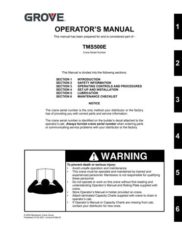
NOTE: Refer to (Figure3-4) for terms to know in determining lifting capacities.
The load chart contains the lifting capacities of the crane in all allowable lifting configurations, and must be thoroughly understood by the operator.
The load chart is divided into capabilities limited by crane structural strength and stability which is shown by a bold line across the chart. Structural strength limits are above the line and stability limits are below the line.
The left column is the load radius, which is the distance from the axis of the crane rotation to the load center of gravity. The top row lists various boom lengths from fully retracted to fully extended with swingaway extension. The number at the intersection of the left column and top row is the total load limit for that load radius and boom length. The number in parentheses below the total load limit is the required boom angle (in degrees) for that load. Boom lengths between increments should always be treated as if it were the next longer length. For example, if the actual boom length is 15.2m (50 ft) and the chart shows boom lengths of 14.616.4 m (48 - 54 ft), use the load capacity shown in the 16.4 m (54 ft) column.
Another important section is the range diagram. The range diagram shows the operating radius and tip height that can be achieved at a given boom length and angle. If the operator knows the radius and tip height required for a specific lift, the angle and boom length can quickly be determined from the range diagram. Or if he knows the boom length and angle, he can quickly determine the tip height and operating radius.
A lifting diagram is included for over-side, over-rear, and over-front lifting areas. The lifting area diagram shows that the locations of the outrigger stabilizer cylinders in the full extended position are used to mark the boundaries of the lifting areas.
Another section contains notes for lifting capacities. Be sure to read and understand all notes concerning lifting capacities.
The load chart also gives weight reductions for Grove Manitowoc load handling devices such as hookblocks, headache balls, boom extension sections, etc, which must be considered as part of the load. The weight of any other load handling devices such as chains, slings, or spreader bars must also be added to the weight of the load.
NOTE: The information in the following paragraph is an example of how to compute a lift. The numbers used in the example may not coincide with the load chart in the crane cab.
Problem: A concrete beam weighing 2268kg (5000lbs) needs to be lifted to a height of 9.1m (30ft) at a radius of 15.2m (50ft) (maximum). The range diagram indicates the boom must be extended to 18.9m (62ft) in order to reach a height of 9.1m (30ft) at a radius of 15.2m (50ft).
First we need to check the crane for load handling devices. In our example, the crane is equipped with a auxiliary boom nose (rooster sheave) and a five ton headache ball. The rooster sheave is 50kg (110lbs), and the headache ball is 78kg (172lbs) for a total of 128kg (282lbs). The lift requires slings and spreader bars weighing 159kg (350lbs) which makes the total weight for the load handling devices 286kg (632lbs).
A check of the load chart for a 15.2 m (50 ft) radius and 19.5m (64ft) of boom length shows a capacity of 3601 kg (7940lbs) on outriggers over-front and 4970lbs on outriggers 360degrees. We subtract the load handling weight of 632lbs from the load capacity of 3601kg (7940lbs) and 2254kg (4970 lbs). The result is a weight capacity of 3315kg (7308lbs) over-the-front and 1968kg (4338lbs) for 360degrees. We are constricted in making the lift over-front only and the boom angle will be about 29degrees.
Crane Functions
Danger
Crushing Hazard
•Death or serious injury could result from being crushed by moving machinery or by improper set-up on outriggers.
•Ensure all pins and floats are properly installed and the outrigger beams are properly extended before lifting on outriggers.
•Stand clear while outriggers are being extended or retracted.
Danger
Tipping Hazard
Serious injury or death could result from improper crane set-up on outriggers.
Center front stabilizer must be properly extended before operating crane on outriggers.
Before extending center front stabilizer:
•Boom must be retracted and in boom rest.
•Main outriggers must be properly extended and crane leveled.
Center front stabilizer will retract when any main outrigger stabilizer is retracted.
If any main outrigger stabilizer is extended or retracted after initial set-up, center front stabilizer must be reset after repeating bulleted steps above.
Setting The Outriggers
NOTE: The park brake must be set and the HYDRAULIC BOOST switch must be in the LOW position before the outriggers will operate.
Caution
Air Suspension Damage
Failure to follow this instruction may result in air suspension damage.
Before raising crane on outriggers, position air suspension control valve lever to DEFLATE.
The outrigger control switches are located on the outrigger control box located in a pocket at the front of the superstructure cab.
The remote mounted outrigger control panels located on each side of the carrier can be used to control the outrigger beams for that side only. All stabilizer cylinders can be operated from either remote outrigger panel.
The center front stabilizer can be controlled from either panel. Carrier mounted controls should only be used for preliminary set-up. Use the superstructure cab controls for final set-up and leveling.
NOTE: The extend/retract switch will operate both the outrigger beams and stabilizer cylinders.
1. Position extend/retract switch to extend position.
2. Position outrigger beam selector switch in direction of beam being extended. The outrigger beam should begin to extend. Refer to Engaging the Mid-Extend Lock Pin if the crane is to be operated at the mid-extend position.
Danger
All four outrigger beams must be equally positioned (fully retracted, to the mid position vertical stripe, or fully extended) before beginning operation.
3. Activate the desired stabilizer switch.
4. Extend each stabilizer, until the floats touch the ground. NOTE: More than one stabilizer may be extended at one time.
5. After all floats are on the ground, extend the front stabilizers about 8 to 10 cm (3 to 4 inches) and then extend the back stabilizers the same distance. Repeat until all tires are off the ground.
Danger
All four outrigger beam lock pins must be engaged before operating from the mid-extend position.
Danger
Operator must select proper load chart and LMI program for the outrigger position selected.
6. Repeat step 5 until all wheels are clear of the ground and the crane is level as indicated by the sight level bubble located on the right side of the cab. If it is suspected that the bubble level indicator is out of adjustment, verify and adjust the bubble level as follows: a. Locate the crane on a firm level surface. b. Extend and set the outriggers. Level the crane, as indicated by the bubble level indicator. c. Place a miracle pointer, carpenter level, or similar type device on a machined surface such as the turntable bearing or bearing mounting surfaces. d. Level the crane with the outriggers as indicated on the device used in step (c). e. Adjust the bubble level indicator with the mounting screws to show level.
Engaging the Mid Extension Lock Pin
1. Turn the locking pin 90° from its stowed position and allow the pin to rest on top of the outrigger beam.
NOTE: It may be necessary to jog the outrigger extension/ retraction switch slightly to ensure proper pin engagement.
2. Slowly extend or retract the outrigger beam, allowing the locking pin to drop into the hole in the top of the outrigger beam, engaging the outrigger beam at the desired length.
Stowing the Outriggers
1. Position the extend/retract switch to the retract position.
2. Activate the desired stabilizer cylinder switch.
3. Repeat steps 1 and 2 until the crane is resting on all four wheels and the stabilizer floats are several inches off the ground.
Warning
To prevent serious injury keep feet and hands clear of floats when unlocking the floats from the stabilizers.
4. Release the locking levers and allow the floats to drop to the ground.
5. Continue to retract the stabilizers until they are fully retracted.
6. Position outrigger selector switch in directions of beam being retracted. The appropriate outrigger beam should begin to retract.
NOTE: More than one outrigger beam may be retracted at one time.
7. After all outriggers have been fully retracted, stow the outrigger floats.
8. Ensure the stabilizer floats are properly stowed in their holding racks. If stowing the optional aluminum floats, they must be positioned in the rack with the handle positioned as shown in (Figure3-5).
Stowing the Mid-Extend Lock Pin
1. Retract the outrigger extension/retraction cylinder.
NOTE: If the lock pin is wedged in the hole in the outrigger beam, it may be necessary to jog the outrigger extension/retraction switch slightly while pulling upward on the pin.
2. Lift the lock pin and turn it 90° to its stowed position.
Setting the Center Front Stabilizer
Danger
Tipping Hazard
Serious injury or death could result from improper crane set-up on outriggers.
Center front stabilizer must be properly extended before operating crane on outriggers.
Before extending center front stabilizer:
•Boom must be retracted and in boom rest.
•Main outriggers must be properly extended and crane leveled.
Center front stabilizer will retract when any main outrigger stabilizer is retracted.
If any main outrigger stabilizer is extended or retracted after initial set-up, center front stabilizer must be reset after repeating bulleted steps above.
1. Activate the center front stabilizer switch.
2. Position the extend/retract switch to extend position.
Caution
Do not try to lift or level the crane with the center front stabilizer.
3. Continue to extend the stabilizer until the float is firmly set on the ground.
Stowing the Center Front Stabilizer
1. Activate the center front stabilizer switch.
2. Position the extend/retract switch to the retract position.
3. Fully retract the center front stabilizer.
Swinging the Boom
Danger
Crushing Hazard
Death or serious injury could result from being crushed by moving machinery.
Before actuating swing or any other function, sound horn and verify that all personnel are clear of rotating and moving parts
DANGER
Tipping Hazard
To avoid death or serious injury; Do not elevate or swing boom over side unless outriggers are properly extended and crane is level.
DANGER
When swinging from over-the-front to over-the-side, refer to over-the side load chart and make certain the capacity is not exceeded. Traveling with any load over-the-side is prohibited.
Caution
Disengage 360° swing lock, pin swing lock, and swing brake before swinging.
Extending the Boom
Caution
Never push or pull swing control lever through neutral to the opposite direction to stop swing motion.
To swing the boom, push the SWING control lever forward for right swing or pull back for left swing. Always operate the control lever with a slow, even pressure. Rotation is stopped utilizing the swing brake foot pedal. When rotation is stopped, position the swing brake switch in the ON position to prevent further rotation.
Elevating and Lowering the Boom
Danger
Clear area above and beneath boom of obstructions and personnel before elevating or lowering boom.
Elevating the Boom
To elevate the boom, pull the boom control lever back, and hold until the boom rises to the desired elevation.
Lowering the Boom
To lower the boom, push the BOOM control lever forward and hold until the boom is lowered to the desired position.
Warning
Long cantilever booms can create a tipping condition even when unloaded and in an extended and lowered position.
Danger
Lower boom and let out cable simultaneously to prevent two-blocking.
Caution
The closer the load is to the boom nose, the more important it becomes to let out cable as the boom is lowered.
Telescoping the Boom
NOTE: When the crane is equipped with an auxiliary hoist the telescope function is controlled by a foot pedal.
Warning
When extending the boom, simultaneously let out the cable to prevent two-blocking the boom nose and hook block.
Danger
Check the load chart for maximum load at given radius, boom angle, and length before extending boom with a load.
Push the TELESCOPE control lever forward away from the operator and hold until the boom extends to the desired length.
Retracting the Boom
Warning
When retracting the boom, the load will lower unless the cable is taken in at the same time.
To retract the boom, pull the TELESCOPE control lever back, toward the operator, and hold until the boom retracts to the desired length.
Telescope Control Pedal
The telescope control pedal is used on cranes equipped with an auxiliary hoist. Push on the top of the pedal to extend the boom and push on the bottom of the pedal to retract the boom.
Lowering and Raising the Hoist Cable
Warning
Keep the area beneath the load clear of all obstructions and personnel when lowering or raising the cable (load).
Warning
Do not jerk control lever when starting or stopping hoist. Jerking causes load to bounce, which could result in possible damage to the crane.
NOTE: When the load is stopped at the desired height, the automatic brake will engage and hold the load as long as the control lever remains in neutral.
Lowering the Cable
Push the MAIN or AUX hoist control lever forward, away from the operator, and hold until the hook or load is lowered to the desired height.
Raising the Cable
Pull the MAIN or AUX hoist control lever back, toward the operator, and hold until the hook or load is raised to the desired height.
Hoist Speed Range Selection
Caution
Do not change the hoist speed range with the hoist rotating.
Operational Aids
Danger
Electronic equipment on this crane is intended as an aid to the operator. Under no condition should it be relied upon to replace the use of capacity charts and operating instructions. Sole reliance upon these electronic aids in place of good operating practices can cause an accident.
Load Moment Indicator (LMI) System
The Load Moment Indicator (LMI) is an electro-mechanical sensing system designed to alert the crane operator of impending capacity when the system has been properly preset by the operator. The control panel is mounted in the front console of the operator’s cab. When an overload condition is sensed, the system provides the operator with a visual and audible warning, and locks out the control levers to prevent lowering the boom, extending the boom, or raising the main or auxiliary hoist cables.
Three additional features are included within the LMI system:
• Swing Angle Set Limitation
• Work Area Definition
• Anti-two Block Device
Swing Angle Set Limitation allows left and right swing angle to be preset. When the preset angle is reached, the system will provide an audible warning.
Work Area Definition allows the crane operator to describe the crane’s working area by setting up “virtual walls”. They are referred to as virtual walls because they exist in the system and are not real walls. The virtual walls represent obstacles (i.e. buildings, towers, poles, etc.) in the crane’s working range. They are set by defining points along the outer limits of the working area with the tip of the boom. Once the working area has been defined, the system will provide a visual and an audible warning if the boom approaches a virtual wall.
Caution
When defining virtual walls (s). always allow a safe working distance to any obstacles. Never work outside a safe working area as defined by common practice, standards, and manuals.
Warning
There are no cut-outs associated with the swing angle set limitation or the work area definition features.
An Anti-two Block Device is also incorporated into the system to prevent the hook block or headache ball from coming into contact with the boom nose or boom extension. This condition will also cause a lockout of hoist up, boom down, and telescope out, and also provide a visual and an audible alarm.
Refer to the LMI Operator’s Handbook for more detailed information on the function of the LMI system.
Control Lever Lockout System
The control lever lockout system consists of hydraulic solenoid valves (located in the directional control valves) which are in series between the hydraulic remote control valves in the cab and the pilot-operated directional control valves. When the valves are actuated, they prevent pilot flow between the hydraulic remote control valve in the cab and the appropriate directional control valve. The valves are activated in such a manner as to prevent worsening the condition, i.e. boom down, telescope out, or hoist up. The control lever lockout system is used with the anti-two-block system or the load moment indicator (LMI) system.
Crane Travel Operation
Active Restraints
Seat Belts
1. Before fastening a seat belt, always adjust the driver’s seat to the position in which you will drive.
Danger
Keep any shoulder belt slack to a minimum, no more than 25 mm (1 inch). Belt slack beyond the specified amount could significantly reduce the amount of protection in an accident because the belt is too loose to restrain you as intended.
6. To unfasten the belt, push in on the button in the center of the buckle. To store the belt, pull out about 180 mm (5 in) and let go. The belt should retract when the buckle is unlatched. To help prevent damage to the seat belt and interior, before closing the door be sure the belt is fully retracted and the latch plate is out of the way.
Traveling - General
Caution
Disengage the hydraulic pumps for extended traveling, cold weather starting, or engine checks.
2. Pull the belt across your lap and push the latch plate into the buckle until it clicks.
3. To reduce the risk of sliding under the belt during a collision, position the belt across your lap as low on your hips as possible and pull it toward the door to a snug fit so the retractor can take up the slack.
NOTE: The lap/shoulder belt is designed to lock only during a sudden stop or impact. At other times is should move freely.
4. If the shoulder belt is too snug, do the following: a. Pull the shoulder belt out (A) at least 130 mm (5 in) so that when it is left go, it returns to your chest. b. Then pull down on the shoulder belt (B) the least amount needed to ease pressure but no more than 25 mm (1 inch) and let go.
5. To reduce slack in the belt, pull the belt out as you did in step 3.a.
Caution
Check cold tire pressure prior to extended travel. Refer to tire inflation decal on crane.
Caution
Job site travel with deflated suspension must be limited to 8 kM/H (5 MPH).
Attempting to travel at higher speeds may cause drive train component failure.
Do not move the crane until the superstructure has been secured as outlined below.
1. To ensure the axles and/or suspension are not overloaded, adhere to the following.
a. Check that front axle load does not exceed 9526 kg (21,000 lb) and rear axle load does not exceed 18,598 kg (41,000 lb).
b. Refer to certification label on inside of cab door for Gross Axle Weight Rating (GAWR).
2. Ensure all boom sections are fully retracted or set to whatever extension is necessary for balance load on the axles.
3. Ensure the boom is fully lowered into the boom rest.
4. Engage the swing brake.
5. Engage the swing lock.
6. Ensure the swingaway, if so equipped, is properly stowed and secured with mast in stowed position.
7. Ensure the hook block and/or headache ball are stowed securely in the stowage trays provided. They may be stowed reeved or unreeved.
8. Ensure the outrigger stabilizers and outrigger beams are fully retracted and the floats are removed.
9. Ensure the center front stabilizer is fully retracted. Float remains installed
10. Ensure the stabilizer floats are properly stowed in their holding racks (Figure 3-5). If stowing the optional aluminum floats, they must be positioned in the rack with the handle positioned as shown in the figure titled Outrigger Float Stowage.
11. Ensure the cover doors on the battery box and sling box are closed.
12. Close and/or install all superstructure cab windows and door.
Traveling With Boom Extension Erected
Travel with boom extension erected is permissible under the following conditions.
1. Boom extension shall be erected at minimum offset with stinger section (if applicable) pinned in fully retracted position.
2. Jobsite travel only on firm, level surface.
3. Main boom shall be fully retracted.
4. Maximum travel speed: 4 km/h (2.5 mph).
5. Swing lock pin shall be engaged.
6. Suspension air bags shall be inflated.
7. Tires shall be properly inflated.
8. Hookblock may be reeved over main boom nose, hanging 0.9 m (3 feet) below nose sheaves.
9. Headache ball may be reeved over boom extension, hanging 0.9 m (3 feet) below sheave.
10. When traveling with the boom over the front: a. Boom angle shall be greater than 15 degrees and less than 40 degrees. b. Any counterweight configuration may be used (Heavy, Standard, or Light).
Automatic Transmission
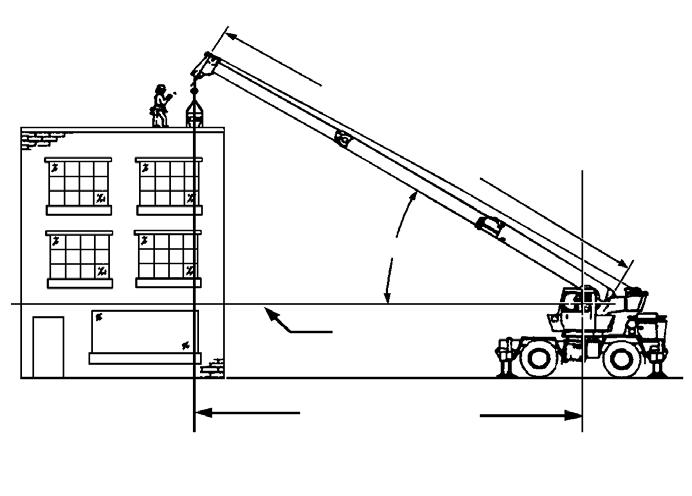
Push-button Shift Selector
The transmission push-button shift selector is located on the right side console. When the engine is first started, the ECU will automatically initialize the transmission to neutral.
NOTE: If fault codes cannot be retrieved, contact your local distributor or Manitowoc CraneCARE for fault code diagnostics procedures.
NOTE: Visually check the display window whenever a button is pushed to ensure the range is selected. A flashing display indicates the selection is inhibited
(D) Push-button
Caution
(D) drive may not be attained due to an active inhibitor. Always apply the service brakes when selecting (D) drive to prevent unexpected vehicle movement and because a service inhibit may be present. When the (D) is flashing, it indicates the shift to D drive is inhibited. Check for active diagnostic codes if drive is not attained.
Caution
Do not idle in (D) drive for more than five minutes. Extended idling in (D) drive can cause transmission overheating and damage. Always select (N) neutral whenever time at idle exceeds five minutes.
Press the (D) push-button to select drive. The highest forward range available will appear as the first digit in the display window. The transmission will start out in the lowest available forward range and advance automatically to the highest range. The second digit in the display window indicates the range the transmission is currently operating in. As travel speed is decreased, the transmission will automatically select lower ranges.
If the engine speed is too high, the shift to (D) will not occur. When (D) is flashing, it indicates the shift to (D) drive is inhibited. Check for active diagnostic codes if (D) drive is not attained.
Up and Down Arrow Buttons
When a lower range is desired after (D) drive has been pressed, press the ( ) down arrow button until the desired range is shown as the second digit in the display window. Likewise, if the transmission is held in a low range by the ( ) down arrow, press ( ) up arrow button to request the next higher range. Continuous pressing of either the ( ) up or ( ) down arrow buttons will request the highest or lowest range available.
NOTE: If engine speed is too high, pressing the ( ) down arrow button may not result in a lower range until the engine speed is reduced.
Mode Button
During normal operation, the MODE button selects a preprogrammed shifting schedule. The default mode uses provides a schedule programmed for economy. Pressing the MODE button selects a schedule programmed for performance. When operating in the secondary mode, the LED in the upper right corner of the push pad illuminates and the schedule name appears in the Mode ID display.
The MODE button is also used while troubleshooting to retrieve diagnostic codes. Simultaneously pressing the ( ) up and ( ) down arrow buttons twice displays the error codes.
NOTE: Fluid level information is displayed after pressing both the ( ) up or ( ) down arrow buttons simultaneously. Press both buttons again simultaneously to obtain diagnostic data.
To advance to the next code in the list, press the MODE button. The Mode LED illuminates to indicate active codes.
To clear active and inactive codes from memory, press and hold the MODE button for approximately 10 seconds. To exit the diagnostic mode, press the ( ) up or ( ) down arrow buttons or wait until the unit automatically exits the diagnostic mode.
(R) Push-button
Caution
(R) reverse may not be attained due to an active inhibitor. Always apply the service brakes when selecting (R) reverse to prevent unexpected vehicle movement and because a service brake inhibit may be present. When the (R) is flashing, it indicates the shift to R reverse is inhibited. Check for active diagnostic codes if R reverse is not attained.
Caution
Do not idle in (R) reverse for more than five minutes. Extended idling in (R) reverse can cause transmission overheating and damage. Always select (N) neutral whenever time at idle exceeds five minutes.
Completely stop the vehicle and let the engine return to idle before shifting from a forward range to (R) reverse or from (R) reverse to a forward range. The digital display will display (R) when reverse is selected.
Push the (R) push-button for reverse travel.
(N) Neutral Push-button
Use (N) neutral when starting the engine, checking accessories and for extended periods of engine idle operation (longer than five minutes). (N) neutral is selected by the ECU during start-up. The digital display will show (N) when neutral is selected. Always select (N) neutral before turning off the engine.
Oil Level Sensor
The transmission shift selector can display the transmission fluid level. By pressing both the ( ) up or ( ) down arrow buttons simultaneously, the shifter display indicates if the transmission fluid level is OK. To obtain an accurate reading:
1. Park the vehicle on a level surface, shift to neutral (N) and set the park brake. Allow 2 minutes for the fluid to settle.
2. Press the ( ) up and ( ) down arrow buttons on the shift selector panel simultaneously. The following conditions must be met before a valid level check is displayed:
- Engine is at idle.
- Transmission fluid temperature is between 60 and 104° C (140 and 220° F).
- Transmission output shaft must be stopped.
- Transmission must be in neutral (N).
3. The shift selector display will indicate the status of the oil level. The alternately displays “oL” to indicate oil level check mode and a code. An example code is “oL HI 02” indicating a the fluid level is 2 quarts above recommended. The possible codes are displayed as follows (Table 3-1):
Table 3-1: Transmission Fluid Fill Codes
DisplayDescription
The fluid level check is delayed where n indicates a countdown number between 8 and 1. Possible reasons for delay:
•Temperature is below 60° C (140° F).
•Temperature is above 104° C (220° C).
Accelerator Control
Caution
Do not make shifts from (N) neutral to (D) drive or (R) reverse when the throttle pedal is depressed. If you shift while the throttle pedal is depressed too far, the transmission will only engage if the throttle pedal is released in the next three seconds. This may cause a sudden movement of the vehicle. Leaving the throttle pedal depressed longer than three seconds causes the transmission to remain in (N) neutral. Avoid this condition by making shifts from (N) neutral to (D) drive or (R) reverse only when the throttle is closed.
Downshift and Direction Change Inhibitor Feature
oL, –n oL, oKFluid Level is OK. oL, Lo, 02 Fluid Level is Low by x number of quarts. In this case, 2 quarts. oL, HI, 01 Fluid Level is High by x number of quarts. In this case, 1quart. oL, – –, nn
•Engine speed is too high (above idle).
•Transmission is not in neutral (N).
•Transmission output shaft is not stopped.
•Fluid is not settled. Crane has not been stationary for 2 minutes.
A fault code exists preventing the fluid level check and n n indicates a fault code. Refer to Fluid Level Fault Codes.
Check Transmission Indicator
When the CHECK TR ANSMISSION indicator on the right hand console in the carrier cab is illuminated and the ignition switch is turned off, the tr ansmission will remain in (N) neutral until the condition causing the indicator to illuminate is corrected.
Generally while the CHECK TRANSMISSION indicator is illuminated, upshifts and downshifts will be restricted and direction changes will not occur. Push-button shift selectors do not respond to any operator shift requests while the CHECK TRANSMISSION indicator is illuminated.
There is no speed limitation on upshifting, but there is a limitation on downshifting and for shifts which cause a direction change such as (D) drive to (R) reverse or (R) reverse to (D) drive.
Manual range downshifts will not occur until a calibration output speed (preset) is reached. When a range downshift is manually selected and the transmission output speed is above the calibration speed, the transmission will stay in the range it was in even though a lower range was requested. Apply the vehicle service brakes or a retarding device to reduce the transmission output speed to the calibration speed and then the shift to the lower range will occur.
Rear Tandem Inter-Axle/Cross-Axle Locks
Caution
Do not operate differential locks on dry roads.
To engage the inter-axle or cross axle differential locks for maximum pulling power when approaching slippery or poor road conditions, do the following:
Caution
Do not engage or disengage differential locks while wheels are turning.
1. Stop the crane and position the control lever to the LOCK position.
2. Proceed over the poor road conditions cautiously. When adverse conditions have passed, do the following:
1. Stop the crane and position the control lever to the UNLOCK position.
2. Resume driving at a safe speed.
Service/Parking Brakes
For the most effective braking and maximum life from the brake system components, the following suggestions are made.
1. Air brakes have light pedal operation and the driver is cautioned to use extreme care in application until a good feel is achieved.
2. Use the engine as a brake when approaching a stop or going down a long grade. On a downgrade, use the same transmission gear as would be needed to go up the same grade.
3. When necessary to use brakes to reduce crane speed on downgrades, use a on-and-off application to minimize heat and wear. Do not hold a continuous brake application or slide the wheels.
4. When driving on slippery pavement or under icy conditions, alternately and smoothly apply and release the brakes to prevent skidding.
5. Keep the tires properly inflated. Improperly inflated tires can reduce the efficiency of the brakes.
6. After driving through water, dry the brakes by applying them lightly while maintaining a slow forward speed with an assured clear distance ahead until brake performance returns to normal.
Danger
Stop immediately if low air pressure warning sounds and determine cause of air loss. Stop by downshifting and use engine as a brake. Make final stop using a single brake pedal movement to avoid excessive loss of air and sudden engagement of parking brakes.
NOTE: If the pressure drops over 14 kPa (2psi) per minute with the engine stopped, have the air system checked for leaks.
7. Regularly check the air pressure gauge. System air pressure should never drop below 310 kPa (45 psi). If both systems drop below 310 kPa (45 psi), the automatic spring brakes will actuate. Normal operating pressure is 724 to 862 kPa (105 to 125 psi).
Caution
Do not use parking brake for stopping crane except in case of an emergency, as a severe sudden stop will occur.
Caution
Release brakes before moving crane, or drive train damage will result.
NOTE: Park brake must be set before outrigger controls can be operated.
8. The parking brakes are controlled by a push-pull knob on the front console. Pull the knob out to apply and push the knob in to release the parking brake.
Engine Braking
NOTE: Do not keep a foot lightly on the throttle pedal. This will cause the engine brake not to come on.
By energizing the engine brake, the power producing diesel engine, in effect, becomes a power absorbing air compressor. To retard a crane on a downgrade using the engine brake, the operator selects a gear which will provide a balance between engine speed and road speed, then engages the engine brake. If the engine speed exceeds maximum rated rpm for a desired speed, a lower gear can be selected or intermittent use of the service brakes can be made. This selection of a lowe r gear will generally allow complete control of the crane by the engine brake leaving the service brakes in reserve to be used for emergency stops. With the engine brake turned on, the engine brake will not be energized until the momentum is driving the engine.
1. Position the ENGINE BRAKE On/Off switch to ON.
2. Position the ENGINE BRAKE High/Low switch to either position, depending on the amount of braking desired.
3. Leave off the throttle to activate the engine braking system and slow the crane.
NOTE: The engine braking system will automatically deactivate when the throttle is depressed.
Caution
Before engaging engine brake on slippery roads, be sure crane is maintaining traction.
Stowing And Parking
Danger
Never park crane near holes, on rocky surfaces, or on soft spots. This may cause crane to overturn, resulting in injury or death to personnel.
When parking the crane, do the following.
Published 07-05-07, Control # 098-03
1. Remove the load from the hook.
2. Remove or stow boom extensions if so equipped.
3. Fully retract all boom sections.
4. Lower the boom to normal travel position.
5. Engage the swing brake, swing lock pin, and 360 degree house lock.
6. Retract all stabilizer cylinders and outrigger beams.
7. Turn off CRANE FUNCTION power switch.
8. Park the crane on a stable surface.
9. Apply the parking brakes and if necessary, chock wheels.
10. Ensure all operating controls are in neutral position.
11. Shut down engine following proper procedures specified in this handbook and the applicable engine manual.
12. Remove the keys.
13. Close and lock, if applicable, all windows, covers, and doors.
Crane Shutdown Procedures
The following procedures will extend serviceable life of various crane components, reduce vandalism, and accidents during crane shutdown periods or anytime the crane is left unattended.
1. Perform the procedures found under Recommended Crane Shutdown Procedures.
Danger
Never park crane near holes, or on rocky or extremely soft surfaces. This may cause the crane to overturn, resulting in injury to personnel.
2. Park the crane on a proper surface with the outrigger stabilizers and beams fully retracted. Do not park in a location where it may become frozen to the ground or settle unevenly and overturn.
3. Apply parking brakes and if necessary, chock the wheels.
4. Position all controls to neutral or off.
5. Shut down the engine using the proper procedures as specified by this Handbook and the engine manual.
6. Perform any other specified procedures required at the end of the workday, i.e., drain water from the fuel filterwater separator, refueling, etc.
7. Close all windows.
8. Remove the keys from the crane.
9. Lock up the crane. Install vandal guards, if used.
Danger
Step 10 does not take the place of the prestarting checks which must be performed just prior to using the crane at the next working day.
10. Make a thorough walk around inspection to ensure that all cylinders that can be retracted are retracted. The only exceptions are those cylinders which cannot be fully retracted, i.e., steer cylinders. Also, look for anything that could hinder or prevent starting the next day’s work.
Section 4
Section 4
SET-UP AND INSTALLATION
General
This section provides procedures for installing the hoist cable on the hoist drum, cable reeving, and erecting and stowing the boom extension.
Installing Cable On The Hoist
Caution
If cable is wound from the storage drum, the reel should be rotated in the same direction as the hoist.
NOTE: The cable should preferably be straightened before installation on the hoist drum.
Install cable on the hoist drum in accordance with the following procedure.
1. Position the cable over the boom nose sheave and route to the hoist drum.
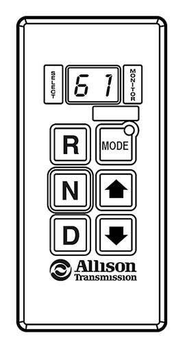
2. Position the hoist drum with the cable anchor slot on top.
3. Insert the cable through the slot and position around the anchor wedge (Figure4-1).
NOTE: The end of the cable should be even with the bottom of the anchor wedge.
4. Position the anchor wedge (Figure4-1) in the drum slot; pull firmly on the free end of the cable to secure the wedge.
NOTE: If the wedge does not seat securely in the slot, carefully tap the top of the wedge with a mallet.
5. Slowly rotate the drum, ensuring the first layer of cable is evenly wound onto the drum.
6. Install the remainder of the cable, as applicable.
Cable Reeving
NOTE: There are two types of cable (wire rope) available on this crane; 6x37WS and 35x7 (non-rotating).
Caution
Using a non-swivel hook ball in conjunction with a tagline or other device to control load spin is preferred when the crane is equipped with rotation resistance wire rope such as 35 X 7 wire rope.
Within the limits of the load and range charts and permissible line pull, multi-part lines allow the operator to raise a greater load than can be raised with a single part line. Various cable reeving (part line) is possible with the boom nose and hook block. This reeving should be accomplished by a qualified rigger using standard rigging procedures (Figure4-3).
In order to quick reeve the hook block without removing the wedge socket on the end of the cable, (Figure4-2).
3155a
Published 07-05-07, Control # 098-03
SINGLE PART LINE
SINGLE PART LINE USING BOOM EXTENSION