9 minute read
CHAPTER 6 SERVICE

from Gehl V4200 V420 (EU) V420 X-Series Skid-Steer Loaders Operator’s Manual 50950233 - PDF DOWNLOAD

Before servicing the machine, unless expressly instructed to the contrary, exercise the MANDATORY SAFETY SHUTDOWN PROCEDURE (page6).
Warning
After service has been performed, be sure to restore all guards, shields and covers to their original positions before resuming operation.
This Service chapter details procedures for performing routine maintenance checks, adjustments and replacements. Most procedures are referred to in the Troubleshooting and Maintenance chapters of this manual. Refer to the Maintenance Interval Chart (page115) for service intervals. Refer to the separate engine manual for engine-related adjustments, lubrication and service procedures.
Note: All service procedures, except those described under the Dealer Services topic are owner-operator responsibilities.
Important: Always dispose of waste lubricating oils and hydraulic fluids according to local regulations or take to a recycling center for disposal. Do not pour onto the ground or down the drain.
Dealer Services
The following areas of component service, replacement and adjustments require special tools and knowledge for proper servicing and should be performed only by your authorized machine dealer: hydrostatic drive components, hydraulic system pumps, valves, hydraulic cylinders, electrical components (other than battery, fuses or relays).
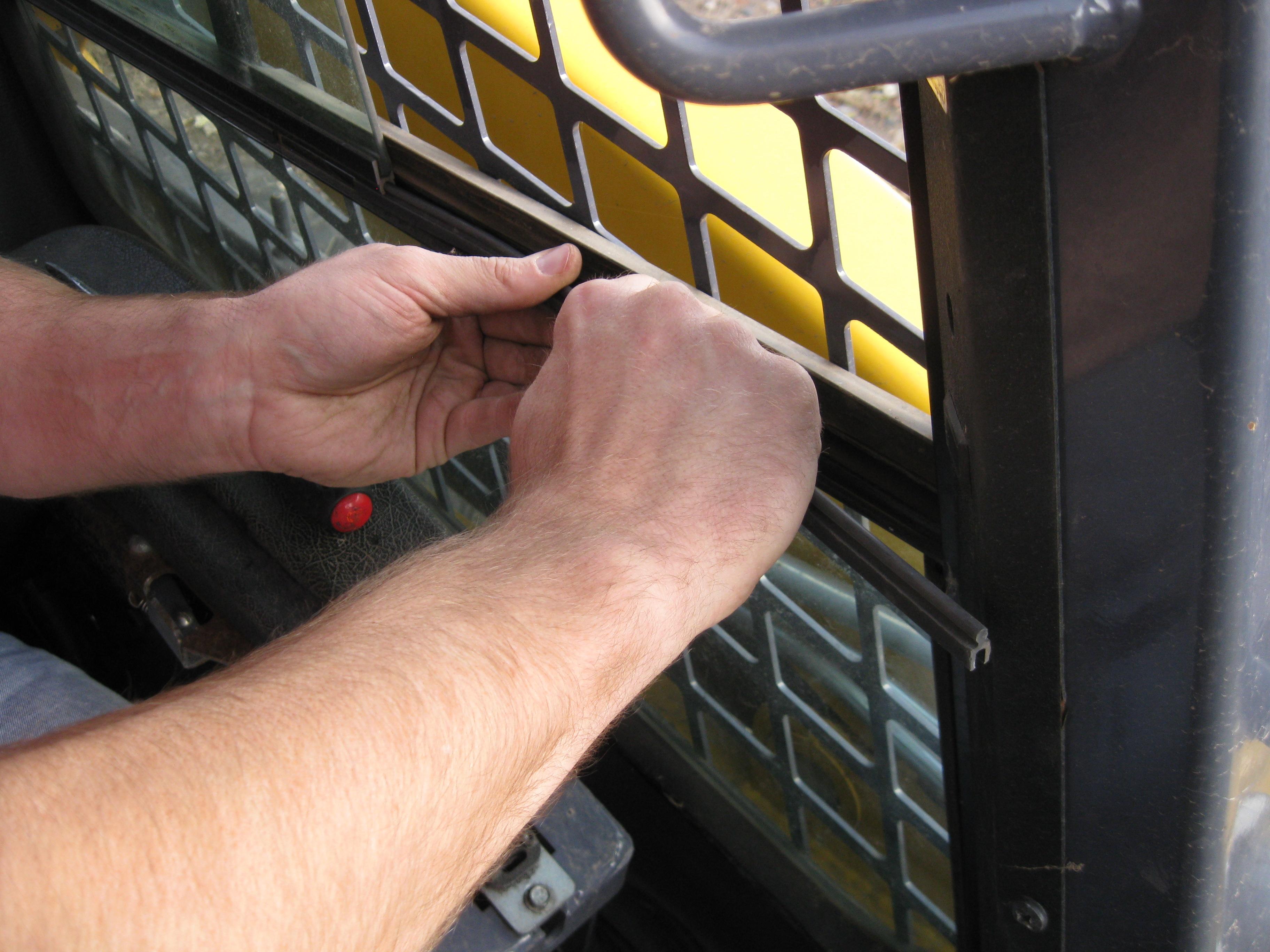
Sliding Side Window Removal Procedure
The sliding side windows inside the ROPS/FOPS can be removed for cleaning. To begin, open the cab door and slide one of the side windows to the rear. Using a non-marring tool, separate the front plastic rail underneath the sliding window from the window frame. Pull the plastic rail forward until it releases from the window frame. Then slide the side window to the front and separate the rear plastic rail from the window frame in the same manner, pulling the rail rearward to release it from the window frame. The sliding side window may now be removed from the ROPS/FOPS. To reinstall the window, reverse the removal steps.
50950233/G0221
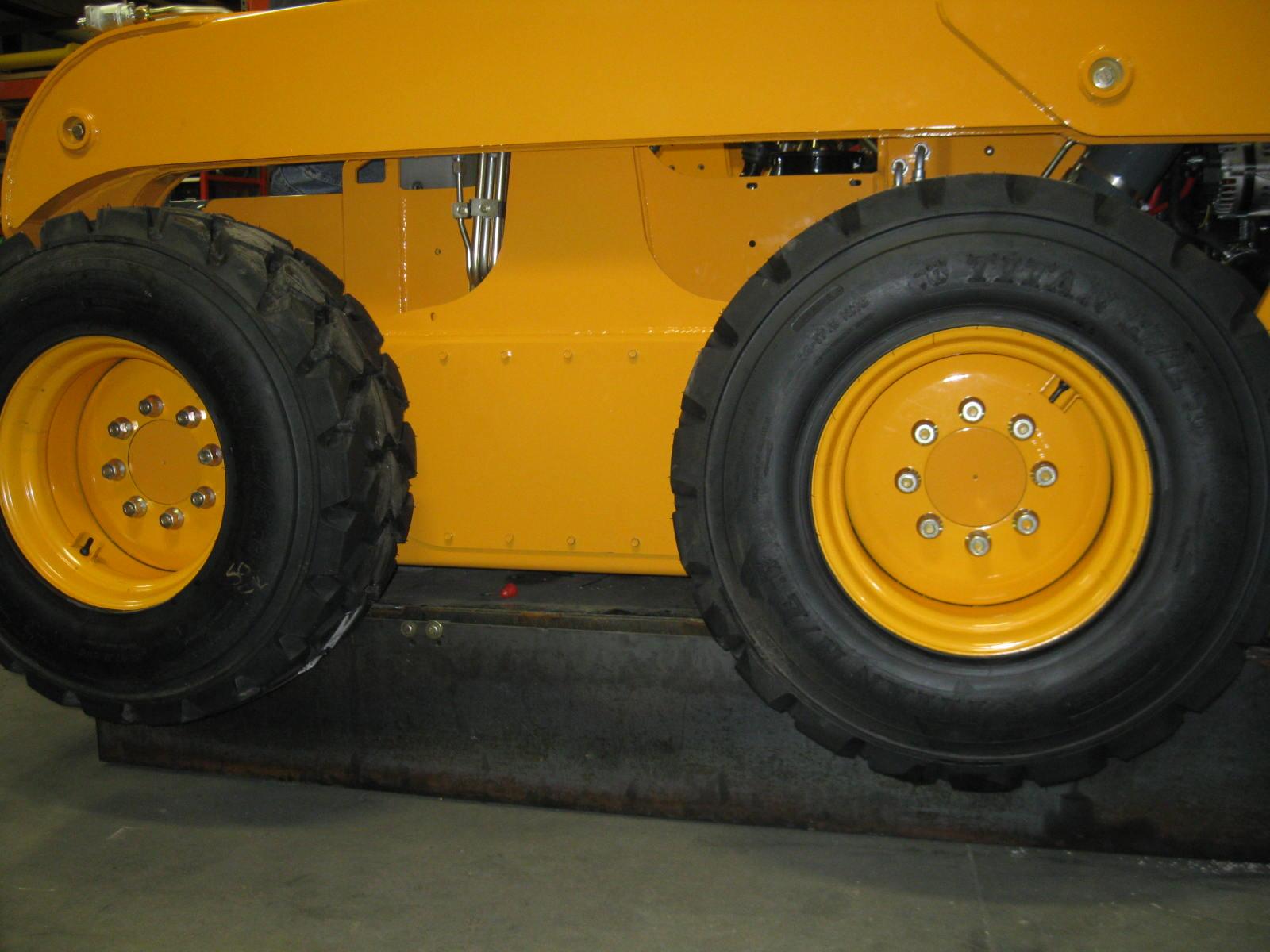
Machine Raising Procedure
To raise the skid-steer machine so all four tires are off the ground, use the procedure below:
Warning
Do not rely on a jack or hoist to maintain the raised position without additional blocking and supports. Serious personal injury could result from improperly raising or blocking the machine.
1.To block the machine, obtain enough suitable blocks (solid wood, hard plastic or metal) so all of the tires are raised off the ground.
2.Using a jack or hoist capable of lifting the fully-equipped weight of the machine (with all attached options), lift the rear of the machine until the rear tires are off the ground.
3.Stack wooden, hard plastic or metal blocks under the flat part of the machine chassis. They should run parallel with, but not touch, the rear tires.
4.Slowly lower the machine until its weight rests on the blocks. If the tires still touch the ground, raise the machine again, add more blocks and lower again.
5.Repeat steps 2 through 4 for the front end. When the procedure is finished, all four tires are off the ground, so they could be removed.
Machine Lowering Procedure
When service or adjustment procedures are complete, the machine can be lowered from the raised position. To lower the machine onto its tires:
1.Using a jack or hoist, raise the front of the machine until its weight no longer rests on the front blocks.
2.Carefully remove the blocking under the front of the machine.
3.Slowly lower the machine until the front tires are resting on the ground.
4.Repeat steps 1 through 3 for the rear of the machine. When the procedure is finished, all four tires will be on the ground and the blocks removed from under the machine.
Engine Compartment Access
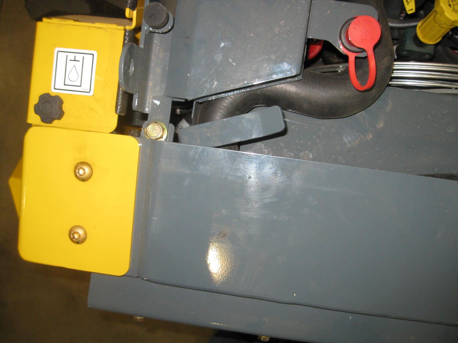
To open the engine compartment, lift the engine cover. Then push the rear door latch down (Fig. 3) and carefully swing open the rear door. There is another rear door latch near the top hinge pin of the door to secure the door open.
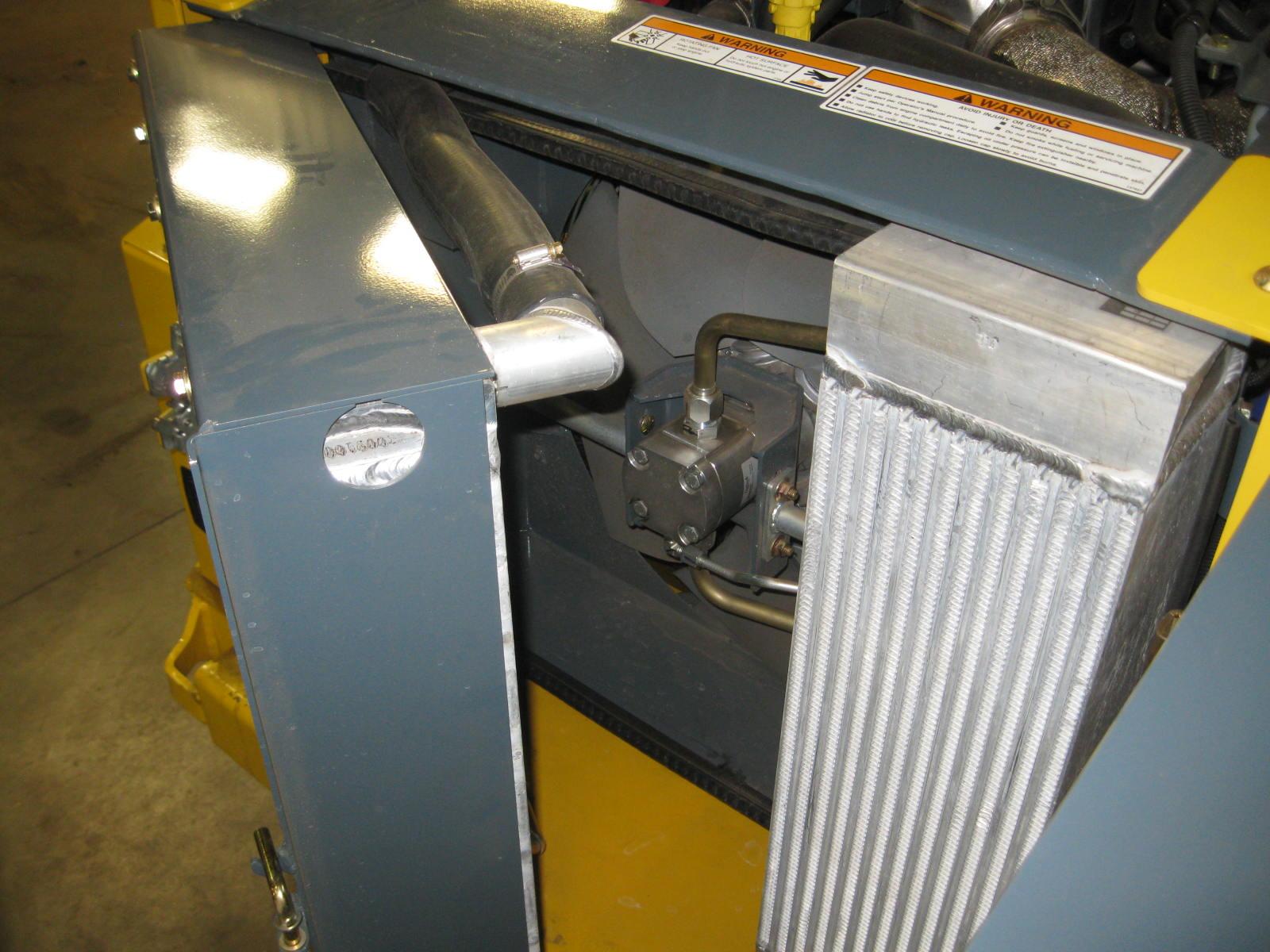
Additionally, the radiator swings out for service (Fig. 4). Pull up the spring-loaded latch that secures the radiator to the chassis bumper and place the latch grip in its welded tab placeholder, then pull the radiator outward.
A pin located at the lower left area of the radiator can be used to secure the cooler open.
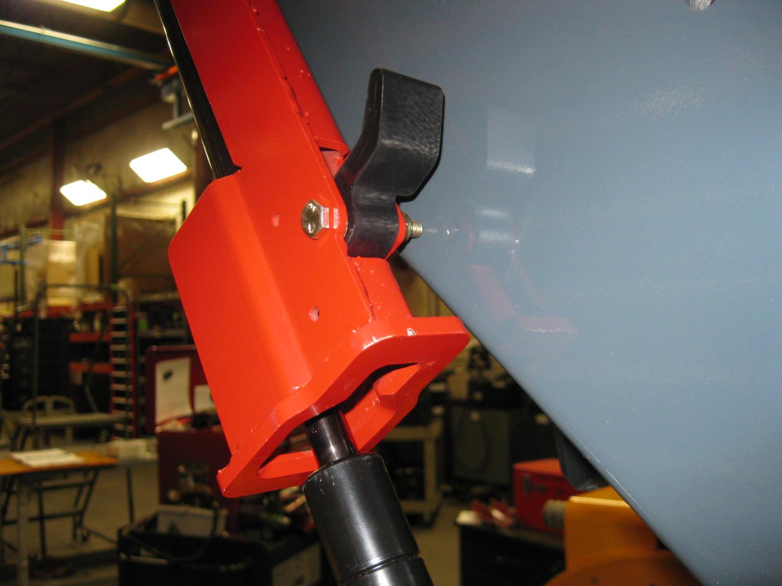
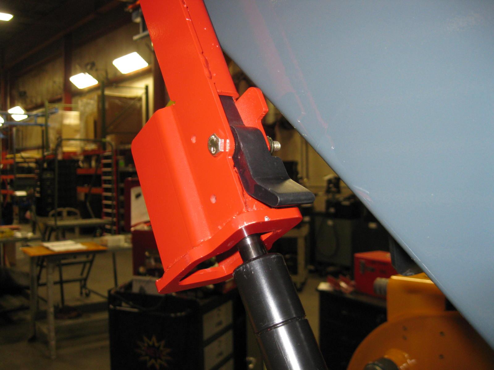
Tilting Back the ROPS/FOPS
A manual lock mechanism is used as a gas spring lock to prevent the raised ROPS/ FOPS from lowering unexpectedly. The manual lock mechanism engages to lock the ROPS/FOPS in a tilted-back position.
To tilt back the ROPS/FOPS, remove two hex nuts on two anchor bolts at the front of the ROPS/FOPS. Tilt it back slowly, moving the control handles out of the way. Two gas-charged springs help tilt it back. A self-actuating lock mechanism will engage to lock when the ROPS/FOPS is in a rolled-back position. To lower the ROPS/ FOPS, return the lock mechanism to the unlocked position (flipper up). Lower the ROPS/FOPS slowly onto the chassis. Reinstall the anchor bolts, washers and locknuts. Refer to the Torque Specifica tions chart (page127) for torque informa tion.
Never operate the machine with the ROPS/ FOPS removed or tilted back. Be sure the lock mechanism is securely engaged when the ROPS/FOPS is tilted back. Be sure to reinstall the anchor bolts, washers and locknuts before resuming operation. Additionally, DO NOT raise or lower the lift arm with the ROPS/FOPS rolled back.
Adjustments
Control Handles
The control handles do not require routine adjustment. Refer to the Service Manual for the initial setup procedure.
Removing Foreign Material
The machine should be cleared daily of dirt and other foreign materials in the following areas:
•around the lift cylinders
•at the front of the machine
•on the hitch, especially around tilt cylinder
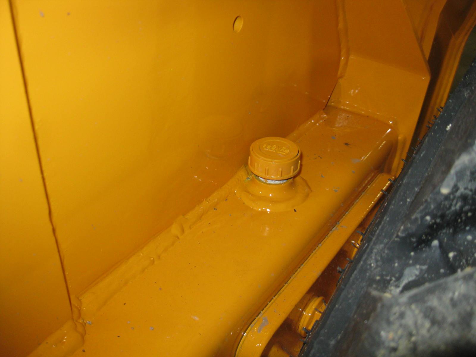
•around the hydraulic oil reservoir breather
•in the engine compartment
•in the operator’s compartment
Important: Build-up of foreign materials in these areas can interfere with the operation of the machine, cause component damage or become a fire hazard.
Lubrication
Listed below are the temperature ranges and types of lubricants for this machine. Refer to the separate engine manual for more information regarding engine lubricants, quantities and grades required.
Note: Refer to the specific service sections for detailed information on periodic checking and replenishing of lubricants.
Refer to Fig.7 for grease fitting locations. Wipe dirt from the fittings before greasing them to prevent contamination. Replace any missing or damaged fittings. To minimize dirt build-up, avoid excessive greasing.
Important: Always dispose of waste lubricating oils and hydraulic fluids according to local regulations or take to a recycling center for disposal. Do not pour onto the ground or down the drain.
System Lubricant

Hydraulic System Oil
Chaincase Oil
Use Petro Canada HVI60, Mobil DTE 15M or equivalent, which contain anti-rust, anti-foam and anti-oxidation additives, and conforms to ISO VG46.
Entire System Capacity: 92,7 L (24.50 U.S. gallons)
Bare Reservoir Capacity: 59,8 L (15.8 U.S. gallons)
Use SAE grade 15W-40 or 10W-30 motor oil. Capacity (each side): 14,2 L (15 U.S. quarts)
Grease Fittings Use lithium-based grease.
Engine Oil
For 250 Hour Change Interval: Use SAE Grade* 5W-30 synthetic, *Service Classification: API certified CK-4 For 500 Hour Change Interval: Must meet one of these Deutz Certifications: DQC III-18 LA, or DQC IV-18 LA Capacity: 9,5 L (10.0 U.S. quarts)
Check Engine Oil Level (page83)
Check Hydraulic Oil Level (page103)
Grease Hitch, Hitch-related Cylinder Pivots and Latch Pins (page77)
Grease Lift Arm Pins (page77)
Check Oil Level in Chaincases (page78)
Change Engine Oil and Filter (page83)
Change Hydraulic Oil Filter (page104)
Change Hydraulic Oil (page104)
Change Chaincase Oil (page78)
Check & Drain Water Separator (page84)
Reservoir Breather
Change DEF Filter
1 - 250 hour engine oil change interval when using API certified CK-4 oil.
2 - 500 hour engine oil change interval when using oil meeting of these Deutz certifications: DQC III-18 LA, or DQC IV-18 LA.
50950233/G0221
Chaincases
There is a chaincase on each side of the machine. Refer to the Maintenance Interval Chart (page115) for change intervals. Refer to the Lubrication chart (page77) for the type of lubricant.
Checking and Adding Oil
1.Park the machine on a level surface and raise the lift arm, refer to the Lift Arm Support Device Engagement Procedure (page28). Shut off the engine and remove the key.
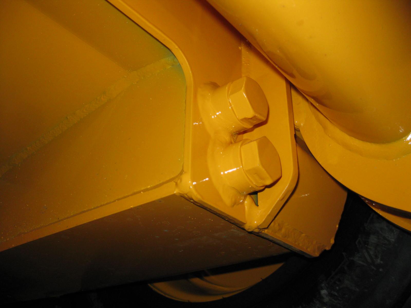
2.At the front of each chaincase and on top of the chaincase there is a fill location underneath a bolt-in cover. Unbolt the cover to access the fill location (Fig.8).

3.Prior to checking, the chaincase must be made level from front to back. At the front of the machine are two plugs in the chassis (Fig.10). The top plug is the oil level check plug, while the lower plug is the chaincase drain plug.
4.Remove the oil level check plug on the front side of the chaincase to be serviced. The oil level should be no more than 3/4 in. (19 mm) below it.
5.If the oil level is low, add oil through the fill plug until the oil level is no more than 3/4 in. (19 mm) below the check plug hole. Reinstall the plugs.
Draining Oil
1.Park the machine on a level surface, or on a sloping surface with the machine facing downhill and the tires blocked.
2.Remove the chaincase drain plug on each chaincase and drain the oil into a suitable container.
3.Reinstall and tighten the drain plugs.
4.Refill the chaincases at the fill plugs per the procedure above.
Drive Chains
Drive chains are located in the chaincase on each side of the machine. Refer to the Maintenance Interval Chart (page115) for tension check interval.
Checking Chain Tension
1.Raise the machine following the Machine Raising Procedure (page72).
2.Rotate each tire by hand. The proper amount of chain defection should be 1/8 inch to 1 inch (3 to 25 mm) forward and rearward tire movement. If the chain defection is more than 1inch (25 mm) or less than 1/8 inch (3 mm) in either direction, the chains should be adjusted.
Adjusting Chain Tension
1.Raise the machine following the Machine Raising Procedure (page72).
2.Remove the tire from the axle to be adjusted.
3.Loosen (but DO NOT remove) the bolts holding the axle to the chaincase.
4. Front Chain Tension – To tighten the front chain, move the front axle assembly toward the front of the machine. To loosen the chain, move the front axle assembly toward the rear of the machine.
Rear Chain Tension – To tighten the rear chain, move the rear axle assembly rearward. To loosen the chain, move the rear axle assembly toward the front of the machine.
5.Proper tension is set when both axles can move by a distance of one rubber tire lug width only.
6.After proper tension is achieved, retighten the bolts.
Important: Be careful not to over-tighten the drive chains. Over-tightening will cause premature drive chain and axle sprocket wear.
7.Reinstall the tire.
8.Repeat steps 2 through 6 for any other axle requiring adjustment.
9.Lower the machine following the Machine Lowering Procedure (page73).
Engine Air Cleaner
Important: Failure to follow proper filter servicing instructions could result in catastrophic engine damage.
The air cleaner assembly consists of an outer (primary) filter element and an inner (secondary) filter element. There is an electrical air filter restriction indicator for monitoring the condition of the elements. If the air filter becomes restricted, this indicator will trigger a lamp light in the right indicator panel to warn the operator that the air cleaner requires service.
The outer element should be replaced only when the restriction indicator lamp lights. The inner element should be replaced every third time the outer element is replaced, unless the outer element is damaged or the inner element is visibly dirty.
Along with a daily check of the restriction indicator, check that the air cleaner intake hose and clamps, and the mounting bracket hardware are properly secured.
Access
Outer Element
1.Carefully pull the outer element out of the housing. Never remove the inner element unless it is to be replaced.
2.Clean out any dirt built up in the housing. Leave the inner element installed during this step to prevent debris from entering the engine intake manifold.
3.Use a trouble light inside the outer element to inspect for bad spots, pinholes or ruptures. Replace the outer element if any damage is noted. The outer element must be replaced if it is oil- or soot-laden.
Note: Cleaning the outer element is not recommended.
Inner Element
Note: Replace the inner element only if it is visibly dirty or if the outer element has been replaced three times.
1.Before removing the inner element from the housing, clean out any dirt built up in the housing. Leave the inner element installed during this step to prevent debris from entering the engine intake manifold.
2.Remove the inner element.
Reinstallation
1.Check the inside of the housing for any damage that may interfere with the elements.
2.Be sure that the element sealing surfaces are clean.
3.Insert the element(s), making sure that they are seated properly.
4.Secure the cover to the housing with the four clamps.
5.Check the hose connections and make sure they are all fitted and tightened properly.
Note: Periodically inspect intake system tubes, rubber elbows and connections. Inspect for cracks, loose fits and loose clamps. Tighten or replace as needed. Intake system must be air tight.
Note: Refer to the Maintenance Interval chart (page115) for change intervals.