13 minute read
Changing Attachments

from Gehl V4200 V420 (EU) V420 X-Series Skid-Steer Loaders Operator’s Manual 50950233 - PDF DOWNLOAD

To prevent unexpected release of the attachment from the hitch, be sure to properly secure the hitch latch pins by verifying that the pin flags moved fully to the outside of the hitch. (Power-A-Tach ® hitch.) Locking pins must be fully engaged through the holes in the attachment frame before using the attachment. The attachment could fall off if it is not locked on the hitch and cause serious injury or death.
Connecting Attachments
1.Activate the switch to unlock the hitch and fully retract the latch pins. (See page34 for a detailed description of this procedure.).
2.Start the machine engine and be sure the lift arm is lowered and in contact with the machine frame.
3.Align the machine squarely with the back of the attachment.
4.Tilt the hitch forward until the top edge of the hitch is below the flange on the back side of the attachment and centered between the vertical plates.
5.Slowly drive the machine forward and, at the same time, tilt the hitch back to engage the flange on the back side of the attachment.
6.Stop forward travel when the flange is engaged, but continue to tilt the hitch back to lift the attachment off the ground.
7.Press the locking Power-A-Tach button on the right instrument panel to extend the hitch pins and to lock the hitch and fully engage the latch pins.
Important: To check that the attachment is properly installed tilt the attachment forward slightly, apply downward pressure to the attachment prior to operating.
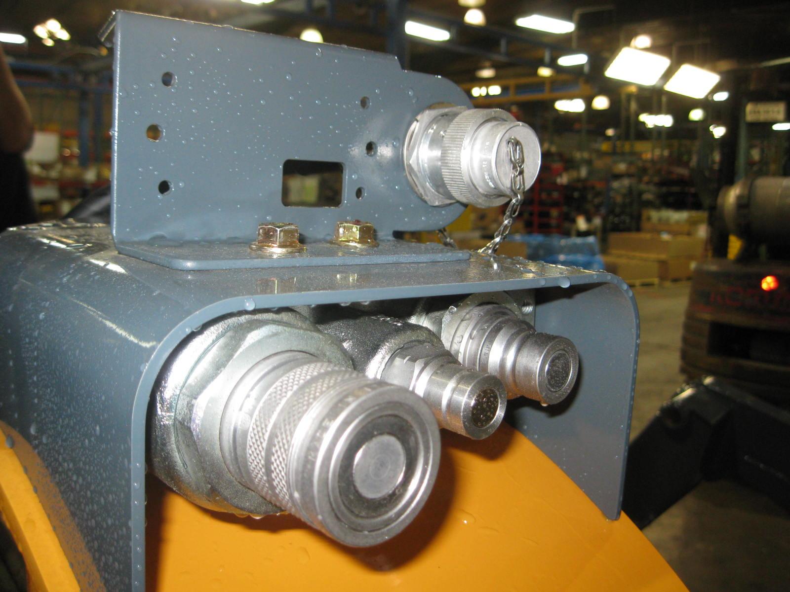
Connecting Auxiliary Hydraulic Couplings
Note: The machine is equipped with quick couplers designed to release trapped pressure. The pressure is automatically released by pushing the coupler inward, returning the oil through the case drain line back to the machine.
Standard-Flow Auxiliary Hydraulics
Couplers are located on the left lift arm. When the auxiliary control switch is activated in either direction, the inside and outside couplers can be “pressure,” or “return” depending on which direction the switch is activated. The smaller center coupler is for the case drain.
High-Flow Auxiliary Hydraulics
Couplers are located on the right lift arm. When the auxiliary control button is activated in either direction, the inside and outside couplers can be “pressure,” or “return” depending on which directional button is activated. The smaller center coupler is for the case drain.
Only connect high-flow attachment couplers to the high-flow auxiliary couplers.
Removing Attachments
1.Tilt the hitch back until the attachment is off the ground.
2.Exercise the MANDATORY SAFETY SHUTDOWN PROCEDURE (page6).
3.With the engine off, leave the operator’s compartment and disconnect the auxiliary hydraulic hoses.
4.Start the engine, press the unlock Power-A-Tach button on the right keypad to retract the hitch pins to unlock the hitch and fully retract the latch pins.
5.Start the engine (if it is not already on) and be sure that the lift arm is fully lowered and in contact with the machine frame.
6.Tilt the hitch forward and slowly back the machine away until the attachment is free from the machine.
Self-Leveling
The selectable feature is intended to automatically keep the attachment level while the lift arm is being raised. The LED button above the self-leveling keypad button illuminates when self-leveling is off.
Self-Leveling Cancel
The self-leveling cancel option allows for deactivation of the self-leveling feature. To deactivate self-leveling, press the self-level cancel button on the keypad. To restore self-leveling, press the button a second time.
Note: Self-leveling defaults to the activated condition is the engine is shutoff.
Using a Bucket
Always maintain a safe distance from electric power lines and avoid contact with any electrically charged conductor or gas line. Accidental contact or rupture can result in electrocution or an explosion. Contact the “Call Before You Dig” referral system at 8-1-1 in the U.S., or 888-2580808 in the U.S. and Canada or proper local authorities for utility line locations before starting to dig.
Driving over Rough Terrain
When traveling over rough terrain, activate the ride control system and drive slowly with the bucket lowered.
Driving on an Incline
When traveling on an incline, travel with the heavy end pointing uphill.
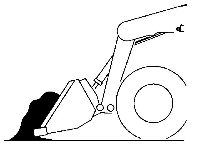
Digging with a Bucket
Approach the digging site with the lift arm slightly raised and the bucket tilted forward until the edge contacts the ground. Dig into the ground by driving forward and gradually lowering the lift arm (Fig.4).

When the bucket is filled, tilt the bucket back and back the machine away from the material. Rest the lift arm against the machine frame before proceeding to the dumping area.
Always carry the loaded bucket with the lift arm resting on the machine frame. For additional stability when operating on inclines, always travel with the heavier end of the machine toward the top of the incline.
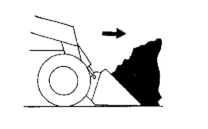
Loading a Bucket
Approach the pile with the lift arm fully lowered and the bucket tilted slightly forward until the edge contacts the ground. Drive forward into the pile, lifting the lift arm and tilting back the bucket to fill it. Back away from the pile (Fig. 5).
Dumping the Load onto a Pile
Carry a loaded bucket as low as possible until the pile is reached. Gradually stop forward motion and raise the lift arm high enough so that the bucket clears the top of the pile. Then, slowly move the machine ahead to position the bucket to dump the material on top of the pile. Dump the material and then back the machine away while tilting the bucket back and lowering the lift arm.
Warning
Never push the “float” button with the bucket or attachment raised, because this will cause the lift arm to lower rapidly.
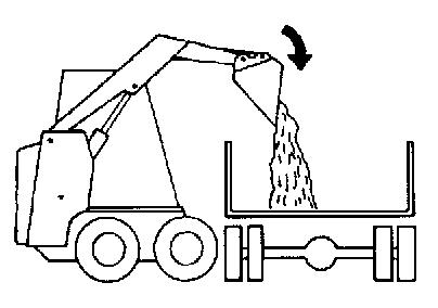
Dumping the Load into a Truck (or Hopper)
Carry the loaded bucket low and approach the vehicle (or hopper.) Stop as close to the side of the truck (or hopper) as possible while allowing for clearance to raise the lift arm and loaded bucket. Next, raise the lift arm until the bucket clears the top of the truck (or hopper) and move the machine ahead to position the bucket over the inside of the truck (or hopper.) Dump the material and then back away while tilting the bucket back and lowering the lift arm (Fig.6).
Dumping the Load over an Embankment
Warning
Do not drive too close to an excavation or ditch. Be sure the surrounding ground has adequate strength to support the weight of the machine and the load.
Carry the loaded bucket as low as possible while traveling to the dumping area. Stop the machine where the bucket extends half-way over the edge of the embankment. Tilt the bucket forward and raise the lift arm to dump the material. Dump the material, and then back away from the embankment while tilting the bucket back and lowering the lift arm.
Scraping with a Bucket
For scraping, the machine should be operated in the forward direction. Position the lift arm down against the machine frame. Tilt the bucket cutting edge forward at a slight angle to the surface being scraped. While traveling slowly forward with the bucket in this position, material can flow over the cutting edge and collect inside the bucket (Fig.7).
Leveling the Ground
Drive the machine to the far edge of the area to be leveled. Tilt the bucket forward to position the bucket cutting edge at a 30 to 45degree angle to the surface being leveled. Then place the lift arm into “float” position and drive the machine rearward, dragging the dirt and, at the same time, leveling it (Fig.8).

Note: The “float” detent is activated by pressing the top middle button on the right control handle.
Warning
Check that the work area is clear of people and obstacles. Always look in the direction of travel.
Vibration Information
Compact construction equipment is generally used in harsh environments. This type of usage can expose an operator to uncomfortable levels of vibration. It is useful to understand exposure to vibration levels when operating compact equipment and what can be done to reduce vibration exposure. As a result, equipment operation can be more efficient, productive and safe.
An operator’s exposure to vibration occurs in two ways:
Whole-Body Vibration (WBV)
Hand-Arm Vibration (HAV)
This section will cover primarily WBV issues, because evaluations have shown that operation of mobile compact construction equipment on jobsites typically results in HAV levels less than the allowed exposure limit of 2.5 m/s2.
Employers in Member States of the European Union must comply with the Physical Agents (vibration) Directive, 2002/44/EC.
Effective control of vibration exposure for an operator involves more than just vibration levels on the machine. The job site, how the machine is used, and proper training all play important roles in reducing vibration exposure.
Vibration exposure results from:
worksite conditions
how the machine is operated
the machine characteristics
Common causes of high WBV vibration levels:
Using a machine that is improper for the task
Work site with potholes, ruts and debris
Improper operating techniques, such as driving too fast
Incorrect adjustment of the seat and controls
Other physical activities while using the machine
Vibration Measurement and Actions
The vibration directive places the responsibility for compliance on employers. Actions that should be followed by employers include:
Assess the levels of vibration exposure.
Determine from this assessment if operators will be exposed to vibration levels above the limits stated in the directive.
Take appropriate actions to reduce operator’s exposure to vibration.
Provide operators with information and training to reduce their exposure to vibration.
Keep good records and update operations and training on a regular basis. If the assessment concludes that vibration level exposure is too high, one or more of the following actions may be necessary:
1.Train operators
Perform operations (accelerating, steering, braking, etc.) in a smooth manner.
Adjust machine speed appropriately.
Adjust the controls, mirrors and seat suspension for comfortable operation.
Travel across the smoothest parts of the work site and avoid ruts and potholes.
2.Choose proper equipment for the job
Use machines with the proper power and capacity.
Select machines with good suspension seats.
Look for controls that are easy to use.
Ensure good visibility from the operator’s position.
3.Maintain the work site
Smooth ruts and fill potholes in traffic areas whenever possible.
Clean up debris frequently.
Vary traffic patterns to avoid exposure to rough terrain.
4.Maintain the equipment
Ensure correct tire pressures.
Check that seat suspension and all controls work smoothly and properly.
Vibration Levels
The following table shows typical Whole-Body and Hand-Arm Vibration levels for Gehl V420 machines.
Whole-Body and Hand-Arm Vibration Levels*
*Whole-Body Vibration levels in accordance with ISO 2631-1. Hand-Arm Vibration levels in accordance with ISO 5349-1.
Highway Travel
If it becomes necessary to move the machine a long distance, use a properly rated trailer. (See Transporting/Towing the Machine on page62.) For short distance highway travel, attach an SMV (Slow-Moving Vehicle) emblem (purchased locally) to the back of the machine. For highway operation, install the optional amber strobe light. Check state and local laws and regulations.
Storing the Machine
If the machine is to be stored for a period in excess of two months, the following procedures are suggested:
1.Fully inflate the tires.
2.Lubricate all grease zerks.
3.Check all fluid levels and replenish as necessary. (Review and follow the engine manufacturers recommendations from the Engine Operator’s Manual.)
4.Add stabilizer to the fuel per the fuel supplier’s recommendations. If the fuel has a mixture of BioDiesel, empty the fuel tank before storing.
5.Turn the electrical disconnect switch to its OFF position and remove the batteries, charge them fully and store in a cool, dry location.
6.Protect against extreme weather conditions such as moisture, sunlight and temperature.
7.Diesel Exhaust Fluid (DEF) quality may be affected after long-term storage. Monitor the fluid and verify the time it has been in storage.
Removing Machine from Storage
1.Check the tire air pressure and inflate the tires if they are low.
2.Connect the batteries and check that the electrical disconnect switch is turned to its ON position.
3.Check all fluid levels (engine oil, transmission/hydraulic oil, engine coolant and any attached implements). (Review and follow the engine manufacturers recommendations from the Engine Operator’s Manual.)
4.Start the engine. Observe all gauges. If all gauges are functioning properly and reading normal, move the machine outside.
5.Once outside, park the machine and let the engine idle for at least five minutes.
6.Shut the engine off and walk around machine. Make a visual inspection looking for evidence of leaks.
Transporting/Towing the Machine
Park the truck or trailer on a level surface. Be sure the vehicle and its ramps have the weight capacity to support the machine. Make sure the vehicle surface and its ramps are clear of debris and slippery material that may reduce traction. Move the machine on and off the vehicle ramp slowly and carefully. Failure to follow these instructions could result in an overturn accident. Towing the machine is not recommended as a means of transportation.
Observe all local regulations governing the loading and transporting of equipment (Reference: U.S. Federal Motor Carrier Safety Regulations, Section 392). Ensure that the hauling vehicle meets all safety requirements before loading the machine. Use the tie down/retrieval points in situations where lifting the machine is not possible and the overall distance by which the machine is to be moved is less than 100 feet (30.5 m) at 6 mph (10 km/hr) or less. The optional brake release package (page53) facilitates machine retrieval in such situations. When transporting a machine:
1.Block the front and rear of the hauling vehicle’s tires.
2.If the machine has an attachment, lift it slightly off the ground.
3.Back the machine slowly and carefully up the ramp onto the vehicle.
4.Lower the machine attachment to the vehicle deck, turn off the engine and remove the key.
5.Fasten the machine to the hauling vehicle at the points indicated by the tie-down decals (Fig.9 and Fig.10).
6.Measure the clearance height of the machine and hauling vehicle. Post the clearance height in the cab of the vehicle.
When towing a machine:
1.Connect the towline to both tie down/ retrieval points at the front or the rear of the machine. Use of only a single retrieval point or connecting the towline to any point on the machine other than the designated retrieval locations could result in machine damage.
2.The towline strength is at least 1.5 times the gross weight of the machine. The towline length is such that the maximum towing angle does not exceed 20°.
Lifting the Machine
The machine can be lifted using a single-point or four-point lift kit, which are available from your authorized dealer.
Warning
•Before lifting, check the lift kit for proper installation.
•Never allow riders in the operator’s compartment while the machine is lifted.
•Keep everyone a safe distance away from the machine while it is lifted.
•Machine may only be lifted with an empty bucket or empty pallet forks, or with no attachment. Never lift the machine with attachments other than those stated.
Lift equipment used and its installation is the responsibility of the party conducting the lift. All rigging MUST comply with applicable regulations and guidelines.
1.Using suitable lift equipment, hook into the lift eyes. Adjust the length of the slings or chains to lift the machine level. Note: The machine may be slightly off level (10 degrees max.) when lifted.
2.Center the hoist over the ROPS/FOPS. To prevent shock loading of the equipment and excessive swinging, slowly lift the machine off the ground. Perform all movements slowly and gradually. As needed, use a tag line to help position the machine and keep it from swinging.
Camera Observation System
A camera observation system is optionally available on all models. The camera observation system utilizes a rear-facing camera mounted within the rear door of the machine to provide full visibility to the region behind the machine of which portions of that region may otherwise be masked by the machine’s structure.
The camera system is configured to turn on automatically when the machine’s ignition switch is moved to the “ON” position. The camera image is displayed on the monitor which is centered above the front door opening of the operator’s compartment.
The vertical viewing angle of the monitor is adjustable by loosening the knobs positioned on either side of the monitor. Prior to operating the machine the operator should check the monitor to verify that the monitor is positioned at the optimum viewing angle for them.
As an integral safety feature of the machine it is important for the operator to verify that the camera system is operating properly prior to moving the machine.
A camera system that is operating properly will display a sharp image that is free of any obstructions when the key is switched on. The displayed image should be centered on the area directly behind the machine. If the displayed image does not meet this criteria the following system checks can be made:
While the system is configured to power up automatically upon key on, depress the system power button at the display to see if the system powers up.
Verify that the electrical connections to the monitor and camera are intact. This includes checking the A/V cable connection into the rear of the monitor and the camera connection to the camera extension cable located in the engine compartment in close proximity to the rear door hinges.
Roll back the ROPS\FOPS and check the camera system harness connections forward of the engine flywheel housing. The connection of the camera system power harness to the accessory power connections in the chassis harness are located in this region. Verify that these connections are intact.
Locate the fuse holder in the camera system power harness near the cable’s interface with the chassis harness. Verify that the two Amp fuse within is intact and fully inserted into the fuse holder terminals. Also, verify that the 20A chassis accessory fuse in the uppermost power distribution module is functional.
If the monitor displays a picture but that picture is not bright and clear, verify that the camera lens is clean and that the camera is properly aligned with the aperture in the rear door. The mounting brackets allow for left/right, up/down, and fore/aft adjustment. When making adjustments, ensure that the resulting pictures displayed on the monitor squarely shows the area behind the machine. Additional troubleshooting measures are detailed in the camera observation system manual for instructions on how to correct any issues.
If the camera system is not able to be made functional after these initial checks, contact your dealer for service. A camera system that is unable to provide a clear image of the rear of the machine should be considered disabled and the machine should not be operated until the camera is made to function properly again.
Back-Up Alarm
A back-up alarm system is standard which serves to warn people working in the area around the machine of the machine’s rearward movement. The back-up alarm is installed within the engine compartment on the inside surface of the rear door. The alarm emits a tone whenever the machine begins to move in the rearward direction.
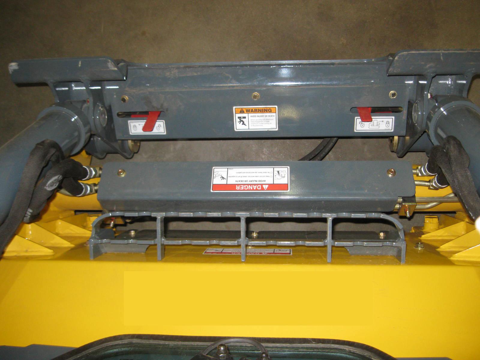
14-Pin Auxiliary Connector

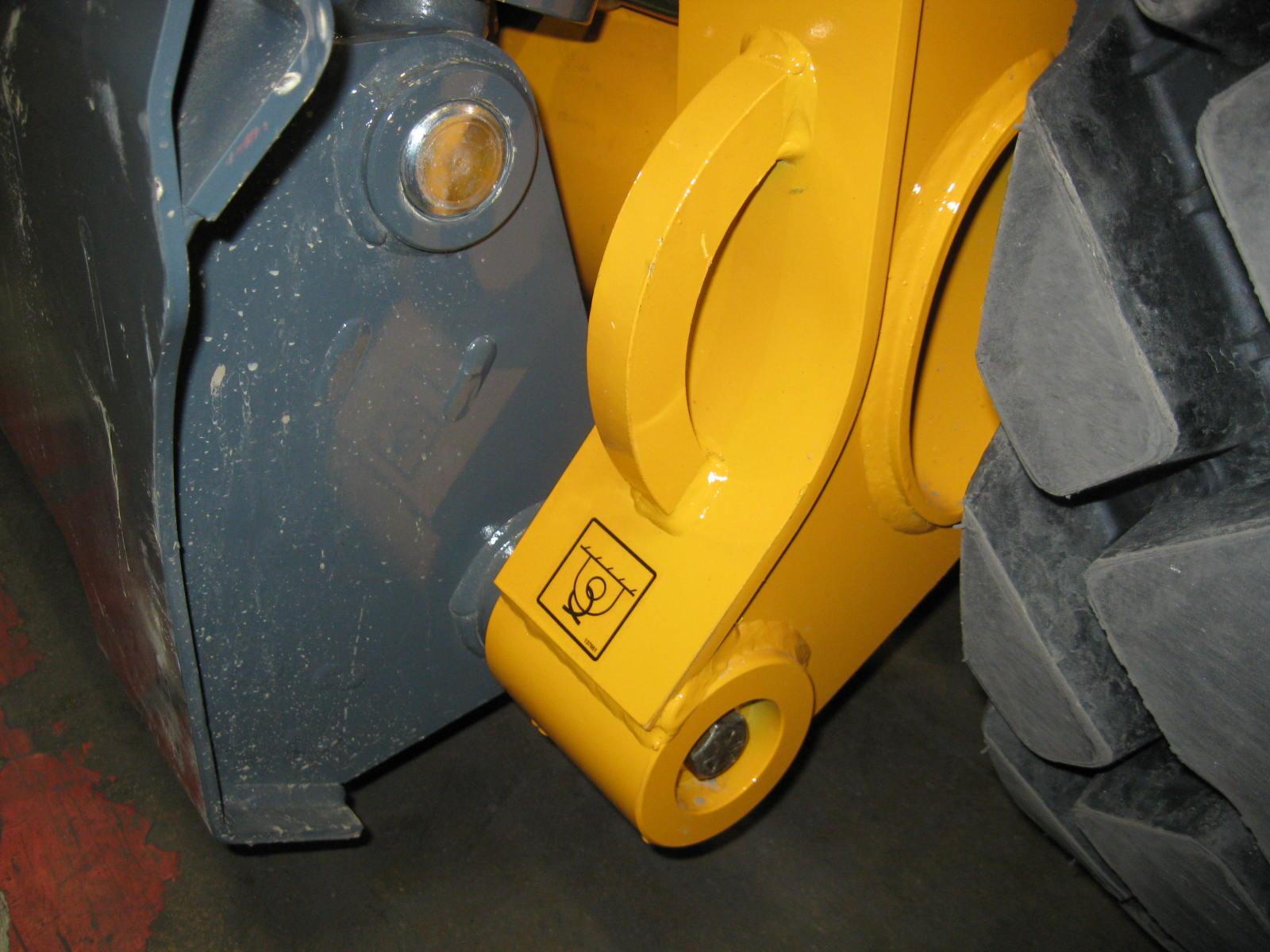
A 14-pin auxiliary connector is optionally available on all models. It is located at the knee joint of the lift arm (Fig.11) and is intended for attachments equipped with 14-pin compliant connections using direct 12 volt actuation control.
Note: Contact your dealer for information about approved 14-pin-equipped attachments.
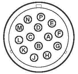
Switch / Pin Assignments
Refer to Fig.12 and Fig.13 and the following table (Table1) for details about the 14-pin control switches and the associated pins in the 14-pin connector.