11 minute read
CONTROLS AND SAFETY EQUIPMENT

from Gehl V4200 V420 (EU) V420 X-Series Skid-Steer Loaders Operator’s Manual 50950233 - PDF DOWNLOAD

Become familiar with and know how to use all safety devices and controls on the machine before operating it. Know how to stop machine operation before starting it. This machine is designed and intended to be used only with Manitou attachments or Manitou Group-approved referral attachments or accessories. Manitou Group cannot be responsible for operator safety if the machine is used with non-approved attachments.
Guards and Shields
Whenever possible and without affecting machine operation, guards and shields are provided to protect against potentially hazardous areas. In many places, safety decals are also provided to warn of potential hazards and/or to display special operating procedures.
Read and thoroughly understand all safety decals on the machine before operating it. Do not operate the machine unless all factory-installed guards and shields are properly secured in place.
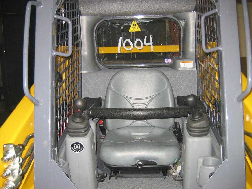
Operator Restraint Bar
Lower the operator restraint bar after entering the operator’s compartment and sitting in the seat. The restraint bar is securely anchored to the ROPS/FOPS. The operator must be seated with the restraint bar in its lowered position to start or operate the machine. Refer to Safety Interlock System on page26 for more information.
The dual joystick restraint bar provides fore-aft adjustment that allows the operator to determine the most comfortable position of the restraint bar. The right and left portions of the restraint bar system can be adjusted independent of one another by pushing the lever on the lower inside of either pad. The restraint pad can then be used to adjust to the desired position. The restraint pad locks in place when it is released.
Warning Warning Warning
Never defeat the operator restraint bar or seat switch electrically or mechanically. Always wear the seatbelt.
Operator’s Seat
The seat is mounted on rails for rearward and forward repositioning. A springloaded lever unlocks the seat position adjustment mechanism.
Air Suspension Seat: Adjust the air sus pension seat by pushing in the knob on the air seat to increase the amount of sus pension. Pull knob out to release air and decrease the suspension level.
Upper-Torso Restraint
1.Restraint Bar
2.Seatbelt
3.Seat Position Adjustment Lever
4.Suspension Seat Weight Adjustment Knob
Fig. 1 Operator’s Seat
Always wear the upper-torso restraint when operating in High speed.
The seatbelt should always be fastened during operation.
Important: Inspect the seatbelt(s) for damage before use, and replace if damaged. Keep seatbelt(s) clean. Use only soap and water to wash seatbelt(s). Cleaning solvents can cause damage to seatbelt(s).
Safety Interlock System
Hydraloc™
NEVER defeat the safety interlock system by mechanically or electrically bypassing any switches, relays or solenoid valves.
An interlock system is provided on the machine for operator safety. Together with solenoid valves, switches and relays, the interlock system:
Prevents the engine from starting unless the operator is sitting on the seat and the operator restraint bar is lowered.
Disables the lift arm, auxiliary hydraulics, attachment tilt and wheel drives whenever the operator leaves the seat, turns the keyswitch to OFF or raises the restraint bar.
Note: The auxiliary hydraulic circuit can be detented in the “on” position for continuous operation with the restraint bar raised and operator out of the seat. (See Auxiliary Hydraulic Controls, page48.)
Testing the Safety Interlock System
Before exiting the machine, check the safety interlock system for proper operation:
Restraint Bar
With the engine running, raise the restraint bar. Test each of the controls. There should be no more than a slight movement of the lift arm, hitch and machine. If there is any significant movement, troubleshoot and correct the problem immediately. Contact your dealer if necessary.
Seat Switch
With the engine off and the restraint bar lowered, unfasten the seatbelt, and lift your weight off the seat. Try to start the engine. If the engine starts, turn off the engine, troubleshoot and correct the problem. Contact your dealer if necessary.
ROPS/FOPS
The Roll-Over/Falling Object Protective Structure (ROPS/FOPS) is designed to provide protection for the operator from falling objects and in a tip over accident, if the operator is secured inside the operator’s compartment by the seatbelt and restraint bar.
Warning
Parking Brake
This machine is equipped applied, hydraulic-released
The parking brake engages when the oper ator lifts or lowers the seat or shuts off the engine. The brake can also be applied manually by using the button located on brake’s default setting button on the keypad machine. A red indicator lights when the parking brake is applied.
Horn
Pressing the right button on the left control handle sounds the horn.
Rear Window Emergency Exit
The ROPS/FOPS rear window has three functions: noise reduction, flying objects protection and emergency exit.
To use the emergency exit, pull on the yellow warning tag at the top of the window and remove the seal. Push or kick out the window and then exit.
See your local automotive glass specialist to reinstall the window.
Lift Arm Support Device
The lift arm support device is used as a cylinder lock to prevent the raised lift arm from lowering unexpectedly. Be sure to install the support device when the lift arm is raised for service. When the support device is not being used, return it to its storage position. The support device is a safety device which must be kept in proper operating condition at all times. The following steps ensure correct usage:
Warning
With the key switch OFF and the solenoid valve working properly, the lift arm will stay raised when the lift control is moved to lower the lift arm. If the valve does not hold the lift am and it begins to lower do not leave the operator’s compartment. Instead, lower the lift arm and exit the machine. Then, contact your authorized dealer immediately to determine why the lift arm lowers while the key switch is OFF.
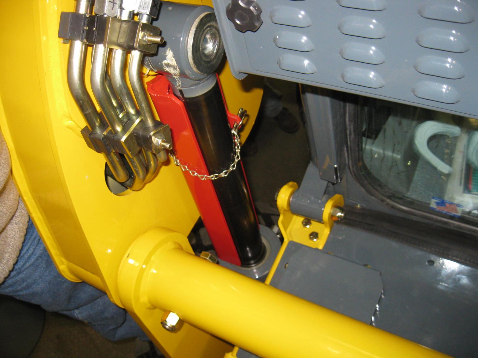
Installation
To install the lift arm support device:
1.Raise the lift arm to full height.
2.Stop the engine.
3.Move the lift arm control to “lower” to verify that the lift arm is being held in the raised position by the safety interlock system.
4.Have an assistant remove the lift arm support device from its storage loca tion (Fig.4) on the left side of the machine and install the lift arm sup port device on the left lift cylinder (Fig.3).
5.Secure the support device to the lift cylinder rod with the attached lock pin and chain.
6.Restart the engine.
7.Slowly lower the lift arm until it engages and locks against the lift arm support device.
8.Stop the engine and exit the machine.
Removal
The safest method of installing and removing the lift arm support device requires two people – one person inside the machine and another person outside the machine to install the support device.
Warning
To return the lift arm support device to its storage position:
1.Start the engine-
2.Raise the lift arm fully-
3.Stop the engine-
4.Verify that the lift arm is being held in the raised position by the safety interlock system.

Warning
With the key switch OFF and the solenoid valve for the safety interlock system func tioning properly, the lift arm will stay raised when the lift control is moved to “lower”. If the lift arm moves, do NOT leave the oper ator’s compartment. Instead, have an assistant remove the support device for you. Then, contact your authorized dealer to determine the reason why the lift arm lowers while the key switch is in the OFF position.
5.Have an assistant remove the lift arm support device.
6.Lower the lift arm and secure the lift arm support device with the lynch pin in the storage location (Fig.4).
Accessory Plug
Dome Light
The dome light is located on the right side of the ROPS/FOPS headliner. Push the dome light to switch it on.
Beacon/Position/Work Lights
Machines have two sets of work lights. The front work lights are located at the top of the ROPS/FOPS. The rear work lights are located at the top of the rear door.
The optional beacon and front/rear work lights are all operated using the beacon/ lights button on the right keypad (Fig.5).
• Beacon: Press the button once to activate the beacon. The LED is lit when the beacon and front work lights are on.
• Beacon and Front Work Lights Press the button twice to activate the beacon, rear marker lights, and the front work lights. The LED is lit when the beacon, rear marker lights, and front work lights are on.
• Beacon and Front/Rear and Work Lights front/rear work lights. Both LEDs are lit when the beacon and the front/ rear work lights are on.
• Off: Pres the button a fourth time to turn off the beacon and the work lights. Both LEDs are off when the beacon and work lights are off.
Switch off the front work lights when traveling on public roads. Work lights can dazzle motorists and cause accidents.
Warning
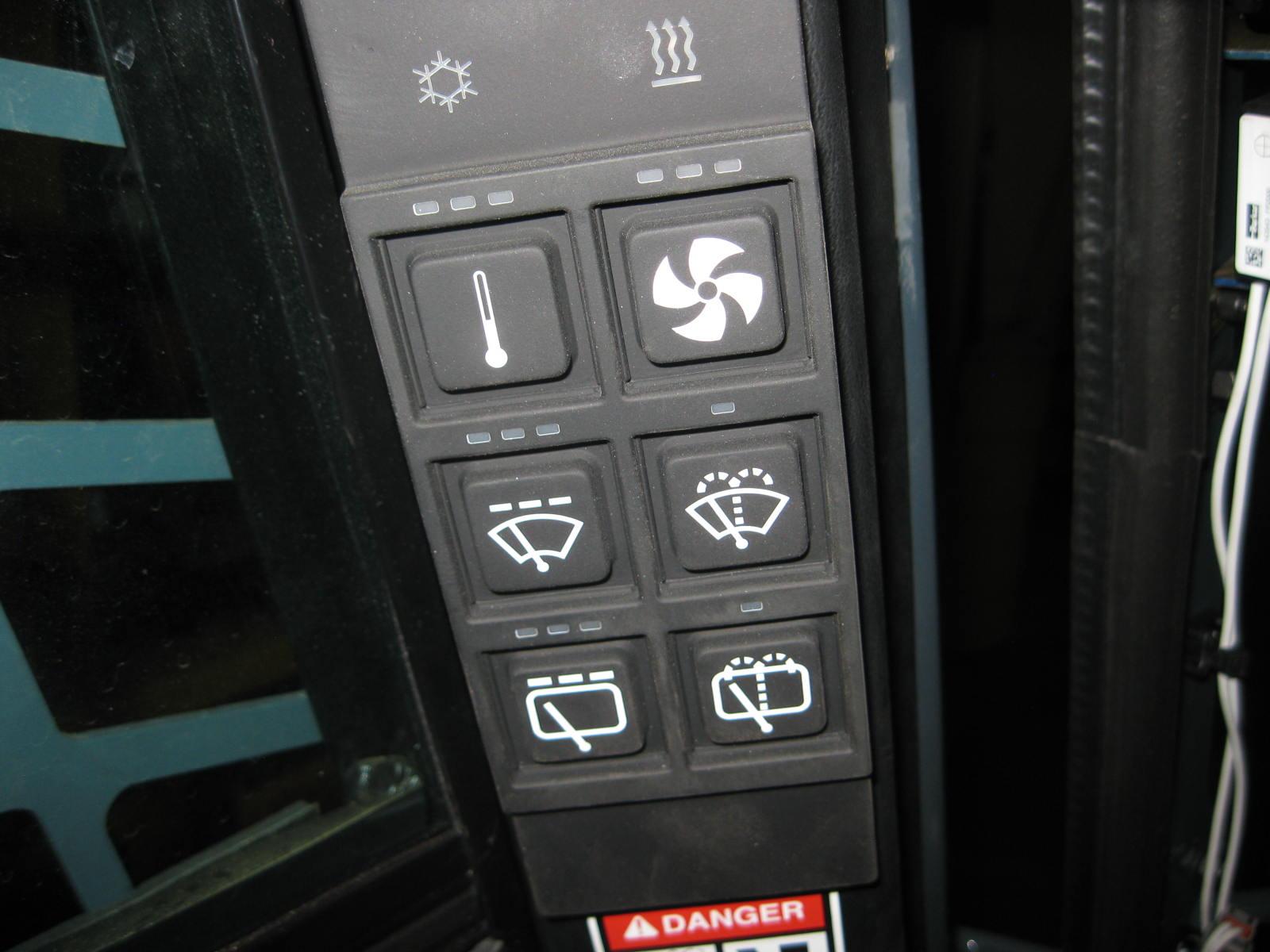
Heater and/or Air Conditioner (option)
Machines with the combination heater/air conditioner have two control buttons on the left keypad for controlling fan speed and heater/air conditioner temperature.
• Fan Speed Control: air flow. Press this button once for the low setting, twice for medium and three times for high. LEDs above the button are lit according to the low, medium and high fan settings. Press this button a fourth time to deactivate the air circula tion fan.
• Temperature Control: button as desired to set the cab fan/ heat/cool settings; additional pressings of this button with increase the heat from low to high. LEDs above the button are lit according to the cool, low, medium and high heat settings. There is also a fan-only setting with this control.
The sequence of the temperature control button pressings are:
•When there are no LED lights lit and no icons are lit. This setting is for fan-only air recirculation in the cab.
•With one press a blue LED lights above the button and the air conditioning icon is lit. This setting is for air conditioning the cab.
•With two presses a blue and yellow LED lights above the button and the heater icon is lit. This setting is for low heat in the cab.
•With three presses a yellow LED lights above the button and the heater icon is lit. This setting is for low to medium heat in the cab.
•With four presses a yellow and red LED lights above the button and the heater icon is lit. This setting is for medium to high heat in the cab.
•With five presses a red LED lights lit above the button and the heater icon is lit. This setting is for high heat in the cab.
•With six presses the temperature control button goes off.
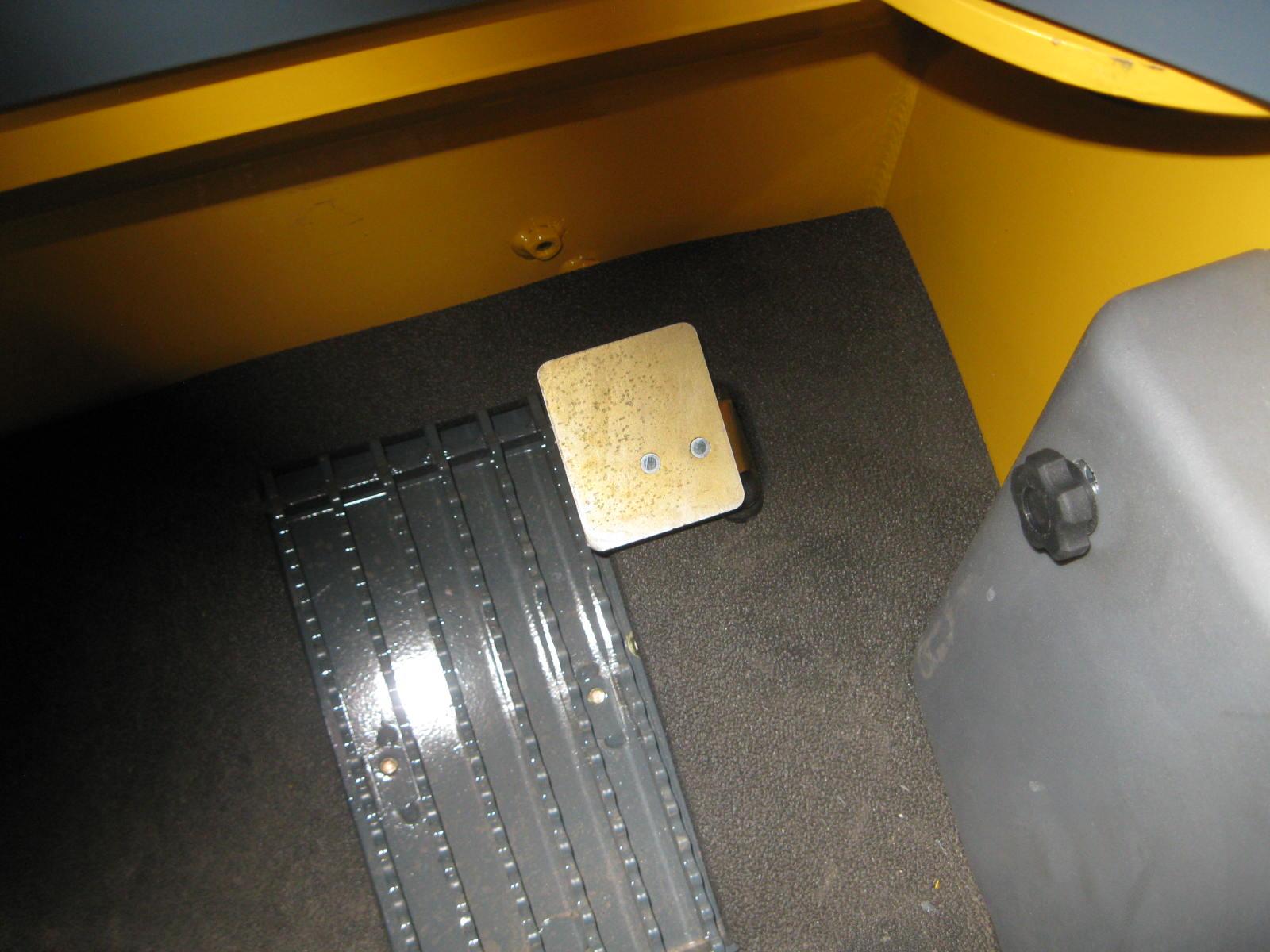
Engine Speed Control
An engine speed control (Fig.7) sets the engine speed. Move the control clockwise to increase the engine speed, and counterclockwise to decrease the engine speed.
A foot pedal (Fig.8) is a secondary throttle, which can be used to override the engine speed control. If the foot throttle is released, the engine will return to the speed set by the engine speed control.
Two-Speed Drive (Travel Mode Only)
Dual joystick machines use the left button on the left control handle for shifting between High (H) and Low (L). Shifting to High allows the machine to exceed 6.5mph (11,6kph), up to a maximum speed of 11.6mph (18,7kph). When the machine is in High (H) an H icon on the right keypad will illuminate (Fig.9). Press the button once to activate, and again to deactivate.
Note: Speed varies slightly with tire size.
at full speed is not recommended and damage may result.
Hydraglide™ Ride Control System
Dual joystick machines use the right button on the right control handle for shifting between normal mode and ride control mode. The ride control system provides a smoother ride over uneven sur faces. Press the button once to activate the system, and again to deactivate. The ride control system is automatically deacti vated when the machine is shut off.
When the machine is in ride control an icon on the right keypad will illuminate (Fig.10)
Warning
inches with a heavy load.
Float Control
Dual joystick machines use the left button on the right control handle for shifting between normal mode and float mode. This mode allows the lowered lift arm to follow the ground contour while traveling over changing ground conditions. Press and hold the button for ten seconds or longer to detent, and press again to deacti vate. The float mode is automatically deac tivated when the machine is shut off
When the machine is in float control an icon on the right keypad will illuminate (Fig.11).
Warning
lower very rapidly. The float mode can be used when the engine has stopped, is unable to be started, and lowering the lift arm is necessary to allow the operator to exit the machine.
Attachment Mounting
The machine is equipped with the Power-A-Tach® hitch for mounting a bucket or other attachments (Fig.12).
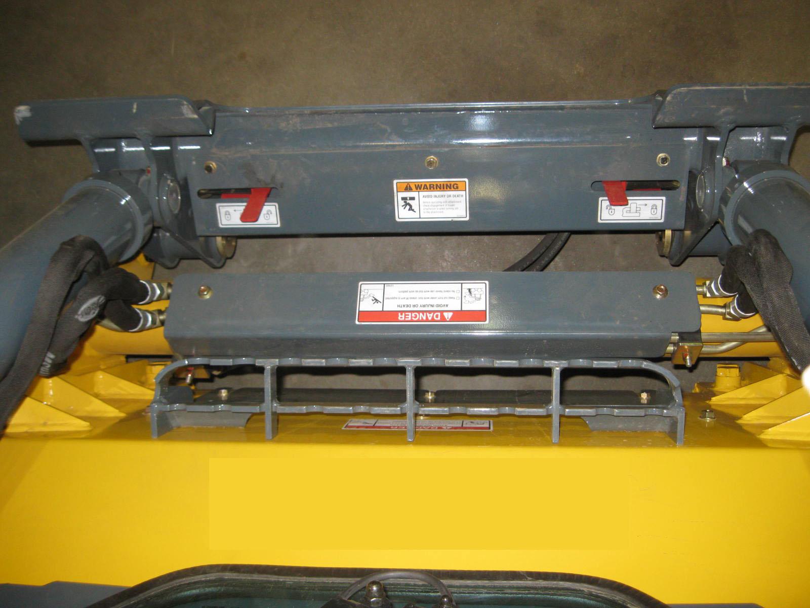
Power-A-Tach® System
The right keypad is used to operate the Power-A-Tach System hitch. The hitch will not operate if the parking brake switch is activated or if the restraint bar is in its vertical (open) position. (Refer to page55 for more information.)
Note: The engine fan speed may fluctuate when operating the hitch.
To retract the hitch pins
1.Press the Power-A-Tach unlock button on the right keypad.
To extend the hitch pins
2.Press the Power-A-Tach lock button on the right keypad.
To prevent unexpected release of the attachment from the hitch, be sure the latch pins are secure by verifying that the pin flags have moved fully to the outside of the hitch.
Multi-Function Display
The multi-function display (Fig.14) is located above the ignition switch. It provides the following functionality:
•Displays operational status such as engine fuel tank level, engine rpm, coolant temperature, operation time ,and system voltage
•Displays error fault codes and input/output diagnostic data
•Is used to initiate an emission component cleaning
•Configures display settings
Fig.14 Multi-Function Display
Table 1: Multi-Function Display
Ref.Item
ANavigation Rocker Button
BOK Button
CIncrease Brightness/Return Button
DDecrease Brightness Button
EStandstill Regeneration/Return Button
Description
Used for general screen navigation and other various functions, depending upon screen and context.
Used for various functions, depending upon screen and context.
Used for various functions, depending upon screen and context:
•Used to increase display brightness. Corresponds to the symbol on the display screen.
•Used to return to previous screen. Corresponds to the symbol on the display screen.
Used to decrease display brightness. Corresponds to the symbol on the display screen.
Used for various functions, depending upon screen and context:
•Switches to the regeneration display mode if the symbol is displayed on the screen. Also initiates regeneration if all appropriate conditions are met.
•Used to return to previous screen. Corresponds to the symbol on the display screen.
F StandtillRegeneration Inhibit ButtonPress for 3 seconds to inhibit regeneration. Displays the symbol.
Gesc (escape) Button
Press to exit secondary screens and return to previously selected status screen.
Warning
If the LCD is broken, take care with any leaking fluid. If LCD fluid gets onto skin, wipe with a cloth and wash the area with mild soap and water. If LCD fluid gets into eyes, thoroughly rinse the eyes with clean water for several minutes and seek medical assistance. If the LCD fluid is swallowed, rinse the mouth thoroughly with clean water, then drink a substantial volume of water and induce vomiting. Then seek medical assistance.
Multi-Function Display Symbols
The following table describes symbols used on the multi-function display. Note: Values may not display for all parameters, depending upon installed options and equipment.
Table 2: Symbol Descriptions
SymbolDescription n/min %
SymbolDescription
Engine crankshaft revolutions per minute.Parking brake.
Accumulated operation time. Time is displayed in hours, and accumulates when the engine is running.
Display brightness increase. Press button (C, Fig. 5) when this symbol is displayed to increase screen brightness.
Battery charging circuit voltage. Display brightness decrease. Press button (D, Fig. 5) when this symbol is displayed to decrease screen brightness.
Fuel level in fuel tank.
Coolant temperature.
IMPORTANT: Running the engine in an overheated condition can damage the engine.
Percentage of engine power based on load.
Critical error warning. Causes error screen(s)to display. See “Error/Status/ History Screens”.
Engine oil pressure warning.
Return to previous. Press button (B, Fig. 5) when this symbol is displayed to return to the previous screen.
Standstill SCRregeneration. See “Selective Catalytic Reduction (SCR) Standstill Regeneration”.
Standstill SCRregeneration inhibit. See “Selective Catalytic Reduction (SCR) Standstill Regeneration”.
Standstill SCRregeneration regeneration inprogress (elevated temperature). See “Selective Catalytic Reduction (SCR) Standstill Regeneration”.
Amber errorcondition warning. Causeserror screen(s) to display.See “Error/Status/ HistoryScreens”.
Engine temperatureDiesel Exhaust Fluid (DEF)