15 minute read
Auxiliary Hydraulic System


Auxiliary hydraulics are used with attachments that have a mechanism requiring hydraulic power.
Warning
Always be sure the auxiliary hydraulic control is in neutral before starting the loader or disconnecting the auxiliary hydraulic couplers.
Standard-Flow Auxiliary Hydraulic Control
Loaders are equipped with a standard-flow auxiliary hydraulic system with flatface couplers. The couplers are located on top of the lift arm on the left side.
Hand/Foot and Joystick Control Loaders

Equipped with Electric Auxiliary: The yellow thumb switch located on the righthand control controls the direction and amount of flow. The farther the switch is moved from center, the higher the flow to the auxiliary circuit. The direction of flow is reversed when the thumb switch is moved in the opposite direction from the center. Pushing the switch upward will pressurize the standard auxiliary male coupler. For continuous operation, move the switch in either direction and push the red trigger button, located on the front of the grip for five seconds, and release. To cancel continuous operation, push the red button or move the yellow switch in either direction.
T-Bar Control Loaders Equipped with Electric Auxiliary: A foot pedal is used to control the direction of hydraulic oil flow. Rotating the foot pedal to the right will pressurize the standard auxiliary inboard coupler. Rotating the foot pedal to the left will pressurize the outboard auxiliary coupler. Depress the pedal for approximately 15 seconds in either direction to detent. To stop the auxiliary detent flow, bump the foot pedal in either direction.
High-Flow Auxiliary Hydraulic Control (Optional)
In addition to a standard-flow auxiliary hydraulic system, loaders may be equipped with a reversible high-flow auxiliary hydraulic system. The couplers are located on top of the right lift arm. The high-flow auxiliary hydraulic system is used for operating certain hydraulic attachments (e.g., cold planer, snowblower) that require higher flows.
The high-flow auxiliary switch controls the direction of hydraulic oil flow. The switch is located on the upper left side instrument panel. Push the right side of the rocker switch for forward flow, or the left side for reverse flow. Pushing the switch to the right will pressurize the highflow male coupler. To disengage, push and release either side of the switch. Turning off the machine, raising the restraint bar, or restarting the engine will also reset the high-flow to neutral. A lamp on either side of the switch will illuminate when the high-flow auxiliary hydraulic system is engaged.

Battery Disconnect Switch
A battery disconnect switch is located at the front of the loader, beneath the left control handle, behind a panel with a swell latch. Turn the switch to the OFF position to disconnect the batteries from the electrical system.

Chapter 4
Operation
Before starting the engine and operating the loader, review and comply with all safety recommendations in the Safety chapter of this manual. Know how to stop the loader before starting it. Also, be sure to fasten and properly adjust the seatbelt(s) and lower the operator restraint bar.
Warning
Before Starting the Engine
Before starting the engine and running the loader, refer to the Controls and Safety Equipment chapter and become familiar with the various operating controls, indicators and safety devices on the loader.
Fuel
Cummins will allow up to a 5% (B5) mixture of BioDiesel.
Starting the Engine
The following procedure is recommended for starting the engine:
1.Carefully step up onto the back of the bucket or attachment and grasp the handholds to enter the operator’s compartment.
2.Close the door, fasten the seatbelt(s) and lower the restraint bar.
3.Verify the following:
the lift/tilt, drive and auxiliary hydraulic controls are in their neutral positions,
the parking brake switch is ON.
Note: When the key is turned to the RUN position, an indicator lamp will light on the instrument panel and a buzzer will sound momentarily to remind users to fasten the seatbelt.
4.Turn the key to the START position.
Note: If temperature is below 32°F (0°C), see Cold-Starting Procedure, on page44.
Important: Do not engage the starter for longer than 15 seconds at a time. Longer use can overheat and damage the starter. If the engine fails to start within 15 seconds, return the key to the OFF position or check for engine error codes. Allow the starter to cool for 20seconds and repeat step 4.
After the engine starts, allow a five minute low idle warm-up period before operating the controls.
Important: If the indicator warning lamps do not go off, stop the engine and investigate the cause.
Cold-Starting
If the temperature is below 32°F (0°C), the following is recommended to make starting the engine easier:
Replace the engine oil with API-CI-4 and SAE 10W-30 oil, or lighter as recommended by the viscosity chart;
Make sure the battery is fully charged;
Install a block heater on the engine. Let the engine run for a minimum of five minutes to warm the engine and hydraulic fluid before operating the loader.
A block heater is recommended for starting in temperatures of 20°F (-7°C) or lower. See your dealer for heater options.
Cold-Starting Procedure
Do not use starting fluid (ether) with pre-heat systems. An explosion can result, which can cause engine damage, injury or death.
1.Turn the key to the RUN position. A wait-to-start symbol will appear on the information center electronic display. Wait for this symbol to go out.
2.Turn the key to the START position.
3.If engine does not start, return key to OFF position and repeat steps 1 and 2.
Stopping the Loader
The following procedure is the recommended sequence for stopping the loader:
1.Check that the drive control handle(s) is (are) in neutral position.
2.Lower the lift arm and rest the attachment on the ground.
3.Turn throttle knob back to the low idle position (and release the throttle pedal for joystick and t-bar control machines). Allow the engine to idle for five minutes if the engine was operated under full load.
4.Turn the keyswitch to the OFF position and remove the key.
5.Move the lift/tilt control to verify that the safety interlock system is preventing movement.
6.Raise the restraint bar, unfasten the seatbelt(s) and grasp the handholds while climbing out of the operator’s compartment.
Note: The skid-steer loader is equipped with a spring-applied automatic parking brake. The parking brake is applied when the operator lifts the restraint bar, leaves the operator’s seat or shuts off the engine, or actuates the parking brake switch.
Parking the Loader
Park the loader away from traffic on level ground. If this is not possible, park the loader across the incline and block the tires to prevent movement.
Brake Release Operation (option)
The loader may have, as an option, a brake release system installed. Utilizing the brake release system disables the parking brake, allowing the loader’s wheels to freely move in either a forward or rearward direction.
Before utilizing the brake release, be sure to secure the vehicle with wheel chocks or tow lines. Verify the loader’s travel paths are clear of personnel before utilizing the brake release system.
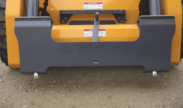
1.Locate the brake release jack and handle. Depending on your particular model, it may be necessary to remove covers and/or open the rear door of the machine.
2.Remove any existing access cover.
3.Position the receiver and insert the jack handle.
4.Push the plunger on the receiver and hold.
5.Begin actuating the pump. Hydraulic pressure developed will retain the plunger so it no longer requires to be pushed. Continue to actuate the pump until the resistance of the jack handle does not increase. There is an internal relief valve in the jack assembly that prevents damage to the motor.
6.You may now tow the loader a short distance or pull it onto a trailer. Depending on the drive motor’s internal leakage rate, the loader may roll easily once the brake is released, or the tires may skid until the oil is forced from the motor.
7. The brake can be reset by pulling up on the plunger or starting the loader.
Jump-starting
If the batteries become discharged or do not have enough power to start the engine, use jumper cables and the following procedure to jump-start the engine.
The ONLY safe method for jump-starting a discharged battery is for TWO PEOPLE to perform the following procedure. The second person removes the jumper cables so that the operator does not have to leave the operator’s compartment with the engine running. NEVER make jumper cable connections directly to the starter solenoid of either engine. DO NOT start the engine from any position other than on the operator’s seat and then ONLY after being sure ALL controls are in “neutral.”
Closely follow the procedure, in order, to avoid personal injury. In addition, to protect your eyes wear safety glasses and avoid leaning over the batteries while jump-starting.
DO NOT jump-start the batteries if they are frozen, because they may rupture or explode.

Note: BE SURE the jumper battery is a 12-volt D.C. battery.
1.Turn the keyswitches of both vehicles to OFF be sure both vehicles are in “neutral” and NOT touching each other.
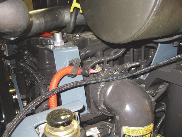
2.Connect the positive (+) jumper cable to the positive (+) remote battery terminal (Figure21) on the disabled loader first. DO NOT allow the positive clamps to touch any metal other than the positive (+) remote battery terminal.
3.Connect the other end of the positive jumper cable to the jumper vehicle’s battery positive (+) terminal.
4.Connect the negative (-) jumper cable to the jumper vehicle’s battery negative (-) terminal.
5.Make the final negative (-) jumper cable connection to the negative (-) remote battery terminal (Figure22) on the disabled loader. DO NOT allow the negative clamps to touch any metal other than the negative (-) remote battery terminal.
6.Start the loader. If it does not start at once, start the jumper vehicle’s engine to avoid excessive drain on the booster battery.
7.After the disabled loader is started and running smoothly, have the second person remove the jumper cables [negative (-) jumper cable first] from the jumper vehicle’s battery and then from the disabled loader, while being careful NOT to short the two cables together. Allow sufficient time for the skid-steer loader batteries to build up a charge before operating the loader or shut off the engine.
Changing Attachments
To prevent unexpected release of the attachment from the hitch, be sure to properly secure the hitch latch pins by rotating the latch levers fully (manual All-Tach® hitch), or by verifying that the pin flags moved fully to the outside of the hitch. (Power-A-Tach® hitch.) Locking pins must be fully engaged through the holes in the attachment frame before using the attachment. The attachment could fall off if it is not locked on the hitch and cause serious injury or death.
On a manual hitch (Figure23), two latch levers engage the latch pins to secure the attachment.
Connecting Attachments
1. Manual hitch: Rotate the latch lever to the right as viewed from the front to fully retract the latch pins.
Power hitch: Activate the switch to unlock the hitch and fully retract the latch pins. (See page26 for a detailed description of this procedure.)
2.Start the loader engine and be sure the lift arm is lowered and in contact with the loader frame.
3.Align the loader squarely with the back of the attachment.
4.Tilt the hitch forward until the top edge of the hitch is below the flange on the back side of the attachment and centered between the vertical plates.
5.Slowly drive the loader forward and, at the same time, tilt the hitch back to engage the flange on the back side of the attachment.
6.Stop forward travel when the flange is engaged, but continue to tilt the hitch back to lift the attachment off the ground.
7. Manual hitch: Exercise the MANDATORY SAFETY SHUTDOWN PROCEDURE (page6). Leave the operator’s compartment and rotate the latch lever to the left when viewed from the front to fully engage the latch pins.
Power hitch: Press the Power-A-Tach switch on the right instrument panel to extend the hitch pins and to lock the hitch and fully engage the latch pins.
Important: To check that the attachment is properly installed tilt the attachment forward slightly, apply downward pressure to the attachment prior to operating.
Connecting Auxiliary Hydraulic Couplings
Note: The loader is equipped with quick couplers designed to release trapped pressure. The pressure is automatically released by pushing the coupler inward, returning the oil through the case drain line back to the loader.
Standard-Flow Auxiliary Hydraulics
Couplers are located on the left lift arm. When the auxiliary control switch is activated in either direction, the inside and outside couplers can be “pressure,” or “return” depending on which direction the switch is activated. The smaller center coupler is for the case drain.
High-Flow Auxiliary Hydraulics (optional)
Couplers are located on the right lift arm. When the auxiliary control switch is activated in either direction, the inside and outside couplers can be “pressure,” or “return” depending on which direction the switch is activated. The smaller center coupler is for the case drain.
Only connect high-flow attachment couplers to the high-flow auxiliary couplers.
Removing Attachments
1.Tilt the hitch back until the attachment is off the ground.
2.Exercise the MANDATORY SAFETY SHUTDOWN PROCEDURE (page6).
3.With the engine off, leave the operator’s compartment and disconnect the auxiliary hydraulic hoses.
4. Manual hitch: Rotate the latch lever to the right when viewed from the front to fully retract the latch pins.
Power hitch: Start the engine, press the top edge of Power-A-Tach switch on the right instrument panel to retract the hitch pins to unlock the hitch and fully retract the latch pins. Release the switch.
5.Start the engine (if it is not already on) and be sure that the lift arm is fully lowered and in contact with the loader frame.
6.Tilt the hitch forward and slowly back the loader away until the attachment is free from the loader.
Self-Leveling
The feature is intended to automatically keep the attachment level while the lift arm is being raised.
Using a Bucket
Always maintain a safe distance from electric power lines and avoid contact with any electrically charged conductor or gas line. Accidental contact or rupture can result in electrocution or an explosion. Contact the “Call Before You Dig” referral system at 8-1-1 in the U.S., or 888-2580808 in the U.S. and Canada or proper local authorities for utility line locations before starting to dig.
Driving over Rough Terrain
When traveling over rough terrain, activate the ride control system and drive slowly with the bucket lowered.
Driving on an Incline
When traveling on an incline, travel with the heavy end pointing uphill.
Digging with a Bucket
Approach the digging site with the lift arm slightly raised and the bucket tilted forward until the edge contacts the ground. Dig into the ground by driving forward and gradually lowering the lift arm (Figure24).
When the bucket is filled, tilt the bucket back and back the loader away from the material. Rest the lift arm against the loader frame before proceeding to the dumping area.
Always carry the loaded bucket with the lift arm resting on the loader frame. For additional stability when operating on inclines, always travel with the heavier end of the loader toward the top of the incline.
Loading a Bucket
Approach the pile with the lift arm fully lowered and the bucket tilted slightly forward until the edge contacts the ground. Drive forward into the pile, lifting the lift arm and tilting back the bucket to fill it. Back away from the pile (Figure25).
Dumping the Load onto a Pile
Carry a loaded bucket as low as possible until the pile is reached. Gradually stop forward motion and raise the lift arm high enough so that the bucket clears the top of the pile. Then, slowly move the loader ahead to position the bucket to dump the material on top of the pile. Dump the material and then back the loader away while tilting the bucket back and lowering the lift arm.
WARNING
Never push the “float” button with the bucket or attachment raised, because this will cause the lift arm to lower rapidly.
Dumping the Load into a Truck (or Hopper)
Carry the loaded bucket low and approach the vehicle (or hopper.) Stop as close to the side of the truck (or hopper) as possible while allowing for clearance to raise the lift arm and loaded bucket. Next, raise the lift arm until the bucket clears the top of the truck (or hopper) and move the loader ahead to position the bucket over the inside of the truck (or hopper.) Dump the material and then back away while tilting the bucket back and lowering the lift arm (Figure26).
Dumping the Load over an Embankment
Do not drive too close to an excavation or ditch. Be sure the surrounding ground has adequate strength to support the weight of the loader and the load.
Carry the loaded bucket as low as possible while traveling to the dumping area. Stop the loader where the bucket extends half-way over the edge of the embankment. Tilt the bucket forward and raise the lift arm to dump the material. Dump the material, and then back away from the embankment while tilting the bucket back and lowering the lift arm.
Scraping with a Bucket
For scraping, the loader should be operated in the forward direction. Position the lift arm down against the loader frame. Tilt the bucket cutting edge forward at a slight angle to the surface being scraped. While traveling slowly forward with the bucket in this position, material can flow over the cutting edge and collect inside the bucket (Figure27).
Leveling the Ground
Drive the loader to the far edge of the area to be leveled. Tilt the bucket forward to position the bucket cutting edge at a 30 to 45degree angle to the surface being leveled. Then place the lift arm into “float” position and drive the loader rearward, dragging the dirt and, at the same time, leveling it (Figure28).
Note: The “float” detent is activated by pressing the top middle button on the right control handle.
Warning
Check that the work area is clear of people and obstacles. Always look in the direction of travel.
Vibration Information
Compact construction equipment is generally used in harsh environments. This type of usage can expose an operator to uncomfortable levels of vibration. It is useful to understand exposure to vibration levels when operating compact equipment and what can be done to reduce vibration exposure. As a result, equipment operation can be more efficient, productive and safe.
An operator’s exposure to vibration occurs in two ways:
Whole-Body Vibration (WBV)
Hand-Arm Vibration (HAV)
This section will cover primarily WBV issues, because evaluations have shown that operation of mobile compact construction equipment on jobsites typically results in HAV levels less than the allowed exposure limit of 2.5 m/s2.
Employers in Member States of the European Union must comply with the Physical Agents (vibration) Directive, 2002/44/EC.
Effective control of vibration exposure for an operator involves more than just vibration levels on the machine. The job site, how the machine is used, and proper training all play important roles in reducing vibration exposure.
Vibration exposure results from:
worksite conditions
how the machine is operated
the machine characteristics
Common causes of high WBV vibration levels:
Using a machine that is improper for the task
Work site with potholes, ruts and debris
Improper operating techniques, such as driving too fast
Incorrect adjustment of the seat and controls
Other physical activities while using the machine
Vibration Measurement and Actions
The vibration directive places the responsibility for compliance on employers. Actions that should be followed by employers include:
Assess the levels of vibration exposure.
Determine from this assessment if operators will be exposed to vibration levels above the limits stated in the directive.
Take appropriate actions to reduce operator’s exposure to vibration.
Provide operators with information and training to reduce their exposure to vibration.
Keep good records and update operations and training on a regular basis. If the assessment concludes that vibration level exposure is too high, one or more of the following actions may be necessary:
1.Train operators
Perform operations (accelerating, steering, braking, etc.) in a smooth manner.
Adjust machine speed appropriately.
Adjust the controls, mirrors and seat suspension for comfortable operation.
Travel across the smoothest parts of the work site and avoid ruts and potholes.
2.Choose proper equipment for the job
Use machines with the proper power and capacity.
Select machines with good suspension seats.
Look for controls that are easy to use.
Ensure good visibility from the operator’s position.
3.Maintain the work site
Smooth ruts and fill potholes in traffic areas whenever possible.
Clean up debris frequently.
Vary traffic patterns to avoid exposure to rough terrain.
4.Maintain the equipment
Ensure correct tire pressures.
Check that seat suspension and all controls work smoothly and properly.
Vibration Levels
The following table shows typical Whole-Body and Hand-Arm Vibration levels for Gehl V400 skid-steer loaders.
Whole-Body and Hand-Arm Vibration Levels*
*Whole-Body Vibration levels in accordance with ISO 2631-1. Hand-Arm Vibration levels in accordance with ISO 5349-1.
Highway Travel
If it becomes necessary to move the loader a long distance, use a properly rated trailer. (See Transporting the Loader on page55.) For short distance highway travel, attach an SMV (Slow-Moving Vehicle) emblem (purchased locally) to the back of the loader. For highway operation, install the optional amber strobe light. Check state and local laws and regulations.
Storing the Loader
If the skid-steer loader is to be stored for a period in excess of two months, the following procedures are suggested:
1.Fully inflate the tires.
2.Lubricate all grease zerks.
3.Check all fluid levels and replenish as necessary. (Review and follow the engine manufacturers recommendations from the Engine Operator’s Manual.)
4.Add stabilizer to the fuel per the fuel supplier’s recommendations. If the fuel has a mixture of BioDiesel, empty the fuel tank before storing.
5.Turn the electrical disconnect switch to its OFF position and remove the batteries, charge them fully and store in a cool, dry location.
6.Protect against extreme weather conditions such as moisture, sunlight and temperature.
Removing Loader from Storage
1.Check the tire air pressure and inflate the tires if they are low.
2.Connect the batteries and check that the electrical disconnect switch is turned to its ON position.
3.Check all fluid levels (engine oil, transmission/hydraulic oil, engine coolant and any attached implements). (Review and follow the engine manufacturers recommendations from the Engine Operator’s Manual.)
4.Start the engine. Observe all gauges. If all gauges are functioning properly and reading normal, move the machine outside.
5.Once outside, park the machine and let the engine idle for at least five minutes.
6.Shut the engine off and walk around machine. Make a visual inspection looking for evidence of leaks.