6 minute read
Engine Diagnostic Chart (cont.)


Hydraulic System
Refer to the Maintenance Interval Chart (page99) for service intervals. Refer to the Replacement Parts chart (page58) for filter part numbers.
Checking Hydraulic Oil Level
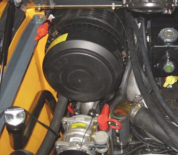
Inside the engine compartment, the loader has a hydraulic tank dipstick left of the air cleaner assembly. To check the level, run the engine at IDLE and remove the dipstick. Clean the dipstick and replace in its holder. Remove the dipstick again and check the fluid level, (Figure47).
Add hydraulic oil as required in the hydraulic oil fill tube. Refer to the Lubrication chart (page63). Replace the fill cap.
Changing Hydraulic Oil Filter
The hydraulic oil filter element is located underneath a flat cover plate on top of the reservoir tank. To change the hydraulic filter element:
1.Park the loader on a level surface and raise the lift arm, refer to the Lift Arm Support Device Engagement Procedure (page22). Shut off the engine and remove the key.
2.Tilt back the ROPS/FOPS, refer to the ROPS/FOPS Procedure (page61).
3.Remove the left side access cover.
4.Clean any dirt/debris off the surface of the filter housing.
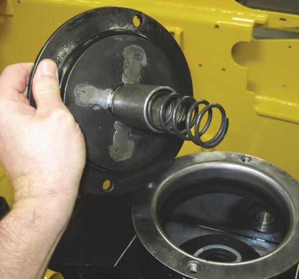
5.Remove four bolts on the cover plate and remove the plate and spring.
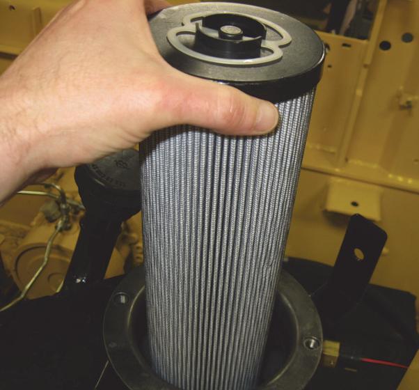
6.Pull up on the filter element and remove it from the reservoir (Figure49).
7.Install the new filter element in the reservoir.
8.After properly positioning the spring, reinstall the cover plate and its hardware.
9.Refill the hydraulic oil reservoir with oil (if needed). Refer to the Lubrication chart (page63).
Changing Hydraulic Oil
The hydraulic oil must be replaced if it becomes contaminated, after major repairs and after 1000 hours or one year of use.
1.Under the loader near the left rear tire, unbolt a small left rear floor plate cover to access the drain plug.
2.Install a catch pan of sufficient capacity under the oil reservoir. See page63.
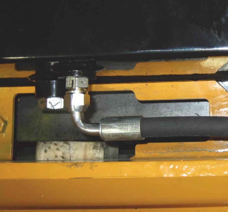
3.Remove the drain plug on the reservoir tank and allow the oil to drain (Figure50).
4.Reinstall the drain plug and floor plate cover.
5.Change the oil filter.
6.Refill the reservoir. Refer to the Lubrication chart (page63).
7.Start the engine and operate the hydraulic controls.
8.Stop the engine and check for leaks at the filter and reservoir drain plug.
9.Check the fluid level and add fluid, if needed.
Bucket Cutting Edge
The bucket cutting edge should be replaced when it is worn to within 1in. (25mm) of the bucket body.
Alternator Belt
Refer to the separate engine manual for setting proper belt tension. If the belt is worn, cracked or otherwise deteriorated, replace the belt following the procedure in the engine manual.
Wheel Nuts
Wheel nut torque must be checked before initial operation and every two hours thereafter until the wheel mounting hardware torque remains at 240ft.-lbs. (325N·m). When wheels are removed and reinstalled this procedure must be repeated.
Lift Arm Pivots
The All-Tach® pivot should be torqued every 250 hours to 380 ft.-lbs. (515 N·m). Refer to the Maintenance Interval Chart (page99).
Cooling System
Important: Check the cooling system daily to prevent overheating, loss of performance and engine damage.
Checking Coolant Level
1.With the engine at operating temperature, open the engine cover. Looking at its visual sight gauge, check that the coolant tank fluid is half way up on the sight glass of the coolant tank (Figure51).
2.Allow the coolant to cool. Do not remove the cap when the coolant is hot. Serious burns may occur.
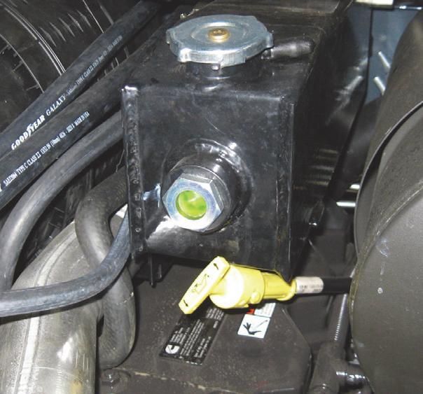
3.Add premixed coolant, 50% water and 50% ethylene glycol, to the tank if the coolant level is low.
Cleaning the Cooling System
Warning
Allow sufficient time for the oil radiator to cool before working on or near it. Parts get extremely hot during operation and can burn you.
The radiator assembly is mounted between the engine and the hinged rear door. When operating correctly, air is blown through the openings between the fins by the engine fan. During operation dust and debris can build up on the engine side of the radiator and restrict air flow through the fins. To remove this restriction, use compressed air and direct the flow through the fins from the rear of the radiator toward the engine.
1.Lower the lift arm and stop the engine. Allow the machine to cool.
2.Raise the engine cover and open the rear door (page60).
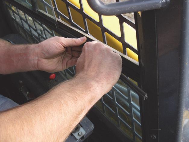
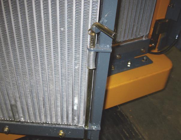
3.Pull up on the radiator lock pin and put it in its placeholder (Figure52), then swing the radiator out (Figure34).
4.As necessary, clean the radiator and air cooler by blowing compressed air through the fins from the rear, toward the engine.
Draining/Flushing the Cooling System
1.Lower the lift arm and stop the engine. Allow the machine to cool.
2.Raise the engine cover and open the rear door (page60).
3.Remove the radiator cap on the coolant tank (Figure51).
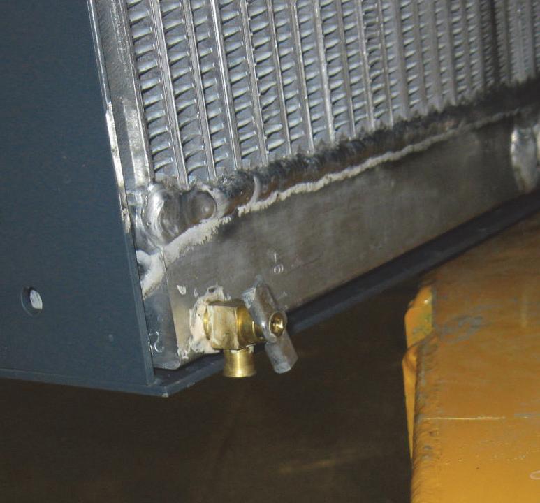
4.Open the drain cock on the radiator (Figure53) and drain the coolant into a suitable container.
Note: Coolant must be drained from the radiator and the engine.
5.Close the drain cock.
Note: Protect the cooling system by adding premixed 50% water and 50% ethylene glycol to the system.
6.Fill the radiator fully and the coolant tank to half full.
7.Reinstall the radiator cap and run the engine until it is at operating temperature.
8.Stop the engine and let it cool. Check the coolant level. Add more fluid, if necessary.
Inflating or servicing tires can be dangerous. When possible, trained personnel should service and mount tires. To avoid possible death or serious injury, follow the safety precautions below.
To keep tire wear even, rotate the tires from front to rear and rear to front.
It is important to keep the same size tire on each side of the loader to prevent excessive wear on tires, chains, or other damage. If different sizes are used, tires will be turning at different speeds, causing excessive wear.
Note: The tread bars of all tires should point the same direction.
BE SURE the rim is clean and free of rust.
Lubricate the tire beads and rim flanges with a soap solution. Do NOT use oil or grease.
Use a clip-on tire chuck with remote hose and gauge, allowing you to stand clear while inflating the tire.
NEVER inflate beyond 35 psi (240 kPa) to seat the beads. If the beads have not seated by the time the pressure reaches 35 psi (240 kPa), deflate the assembly, reposition the tire on the rim, lubricate both parts and re-inflate. Inflation pressure beyond 35 psi (240 kPa) with unseated beads may break the bead or rim with explosive force sufficient to cause death or serious injury.
After seating the beads, adjust the inflation pressure to the recommended operating pressure.
Do NOT weld, braze or otherwise attempt to repair and use a damaged rim.
Checking Tire Pressure
Correct tire pressure should be maintained to enhance operating stability and extend tire life. Refer to the chart below for proper inflation pressures.
Heater/Air Conditioner Filters
The optional heater and heater/air conditioner include two filters: fresh air intake and recirculation air.
Refer to the Replacement Parts topic (page58) for filter part numbers. Filters should be replaced as needed.
Fresh Air Intake Filter: Located directly behind the cover on the HVAC (heating, ventilating and air conditioning) housing mounted on the upper rear corner of the cab. Remove the threaded knobs on both sides of the cover to access the filter.
Recirculation Air Filters: Located behind the covers in the headliner directly above the rear window. The access, remove the screws on either side of the covers.
Important: Keeping the cab clean will reduce need for service and help ensure proper air conditioner and heater operation. Failure to do so can cause evaporator and heater core plugging, fan noise, vibration and failure.
Electrical System
Fuse Panels
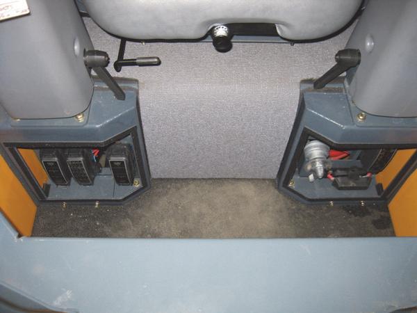
The main fuse panels (Figure54) are located behind two covers in the operator’s compartment directly behind the operator’s foot area, as well as the electrical engine disconnect switch. The illustrations of the fuse panels on this page may be rotated for easier reading.
Battery
Before servicing the batteries or electrical system, be sure the electrical engine disconnect switch is in the OFF position or disconnect the negative (ground) battery cable.
Warning
The batteries on the loader are 12-volt, group 24, wet-cell batteries. To access the batteries, remove the floor mat and pull up on the center foam cover (Figure54) between the control handles to release it from its fasteners, then unbolt the metal cover beneath the crossmember.
The battery top must be kept clean. Clean it with an alkaline solution (ammonia or baking soda and water). After foaming has stopped, flush the battery top with clean water. If the terminals and cable connection clamps are corroded or have a build-up, disconnect the cables and clean the terminals and clamps with the same alkaline solution. Apply protective spray to prevent corrosion.
Warning
Explosive gas is produced when a battery is in use or being charged. Keep flames and sparks away from the battery area. ALWAYS charge the battery in a well-ventilated area.
Never lay a metal object on top of a battery, because a short circuit can result.
Battery acid is harmful on contact with skin or fabrics. If acid spills, follow these first-aid tips:
1.Immediately remove any clothing on which acid spills.
2.If acid contacts the skin, rinse the affected area with running water for 10 to 15 minutes.
3.If acid contacts the eyes, flood the eyes with running water for 10 to 15 minutes. See a doctor at once. Never use any medication or eye drops unless prescribed by the doctor.
4.To neutralize acid spilled on the floor, use one of the following mixtures: a.1 pound (0.5 kg) of baking soda in 1 gallon (4 L) of water, or b.1 pint (0.5 L) of household ammonia in 1 gallon (4 L) of water
Whenever a battery is removed, be sure to disconnect the negative (-) battery terminal connection first.