19 minute read
CHAPTER 12 STORAGE

If Baler is to be out of use for a considerable amount of time, the following storage procedure is recommended.
1.Thoroughly clean the Baler, inside and outside, making sure that all crop material and accumulated dirt, etc. are removed.
2.Inside the Bale Chamber and on those areas where the original factory finish has become worn off, liberally coat these surfaces with a rust preventative.
3.Carry out all lubrication detailed in “Lubrication” chapter of this manual. Grease all Fittings and make sure the PTO Drive Tubes and Shields are completely greased. Repack the Wheel Bearings, if required.
4.Raise Baler and insert blocks under the Axle to take the weight off both Tires.
5.Release pressure on Slip Clutch Facings by loosening Slip Clutch Springs.
6.Remove twine from Baler and store the twine balls in a dry area. Store the balls on end to prevent distortion.
7.Check the Baler for signs of damage and worn parts. Repair Baler as necessary and order replacement parts from your authorized GEHL Dealer.
8.Store the unit inside a shed, if possible, or cover the top half of the unit to protect it, if it MUST be stored outside.
9.Reorder and replace any required parts so that the Baler will be ready to operate at the start of the next baling season.
NOTE: Before starting–up next season, go over the Checklists, chapter 3 in the front of this manual.
Chapter 13 Troubleshooting
NOTE: This Troubleshooting guide presents problems, causes and suggested remedies beyond the extent of loose, worn or missing parts and it was developed with the understanding that the machine is in otherwise good operating condition. Refer to the index at the back of this manual for Chapter and Topic page references. BE SURE to exercise the MANDATORY SAFETY SHUTDOWN PROCEDURE (page 8), BEFORE making any adjustments or repairs.
General
Problem Cause Remedy
Pickup is NOT picking-up cleanly.
Excessive number of broken or bent Pickup Tines.
Pickup flotation is NOT properly set.
Replace Tines and adjust Pickup so that Tines pick up crop without digging into the ground.
Readjust flotation following details under Flotation subtopic under Pickup topic in Adjustments chapter.
Improper ground travel speed. Change travel speed. Pickup is set too high. Readjust height following details under Pickup topic in Adjustments chapter.
Flywheel Shear Bolts shearing frequently.
Bales are too heavy.
Loosen bale tension or remove hay Wedges, if present.
Dull Shear Knives. Sharpen Shear Knives per details in Service chapter.
Excessive clearance between Shear Knives.
Adjust Shear Knives per details in Adjustments chapter.
Incorrect Stop Dog setting. Readjust Stop Dog per details under Plunger topic in Adjustments chapter.
Damp crop build-up in Bale Chamber.
Misshaped bales. Incorrect Packer Fork positioning.
Ground travel speed too slow for small amount of material in windrow.
Ground travel speed too fast for the crop material being baled resulting in bunched hay in the bales.
Clean-out Bale Chamber.
Increase or decrease the position of the Packer Fork per details in Adjustments chapter.
Increase the size of the windrows or otherwise travel faster.
Reduce the ground travel speed as heavy crops provide charges which are too large, resulting in misshaped bales.
Hay Dogs are NOT fully penetrating the Bale Chamber. Remove obstruction or trash build–up and inspect for broken Springs.
Front Drive Chain is broken or disconnected.
Repair or replace Chain.
GENERAL (cont.)
Problem Cause Remedy
Excessive Slip Clutch slipping. Clutch Spring Bolts are NOT properly tightened.
Tighten the Bolts until bottomout replace Clutch Discs.
Excessive PTO Shaft noise on cornering. Incorrect PTO Shaft alignment. Realign PTO per details in Preparing For Field Operation chapter. Making too short turns. Make wider turns.
Raggedly cut bale surfaces. Dull Knives. Sharpen or replace Knives.
Knives are incorrectly adjusted. Readjust Knife positions per details under Shear Knife Adjustment topic in Service chapter.
Irregular bale lengths. Improper clearance between Metering Arm and Knurled Roller.
Reajust clearance per details under Metering Wheel topic in Adjustments chapter.
Knurled Roller is loose. Tightly secure retaining Nut. Metering Arm Pivot Linkage is inoperative. Dissamble, clean, reassemble and lubricate Linkage.
Metering Arm arc is NOT true. Reshape to true arc or replace Arm.
Knotter
NOTE: Knotter problems may appear after a long period of operation. Baler will be running well and then, all of a sudden, the Baler starts to mistie. Use the following steps to find and identify a tying or knotting problem:
1.Find the twine from the broken bales.
2.Determine which Knotter has a problem.
3.Determine where or how the knot was miss-made a.One twine has a knot and the other twine doesn‘t b.NO sign of a knot c.Twine broken adjacent to the knot
Problem Cause Remedy
One twine has a Knot and the other twine doesn‘t. Trip Knotter and slowly turn the Needles through their cycle by hand while checking the following:
Needle position in regards to Knotter.
Needle should lightly rub Knotter Frame and clear Cord Disc by 1/16 to 1/8″ (1 to 5.3 mm).
Check Needle to Plunger timing. Adjust for 1/4 to 3/4″ (6 to 18 mm) behind tip of Plunger.
Examine Knotter for loose or broken parts with particular attention to the Bill Hook Jaw and Twine Knife.
Insufficient Twine Retainer tension.
NO sign of a knot. Make sure the Hay Dogs are engaging fully.
Compare a good Knotter with a basd one.
Twine broken adjacent to knot. Determine if twine has been changed.
Replace any broken parts.
Check Retainer Spring setting. Compressed Spring length should be 1-5/8″ (41 mm), with NO twine in the Retainer.
Remove any foreign material and make sure Dogs move freely.
Look for broken or loose parts.
Change twine, if necessary.
Determine if this is a new crop. Check bale tension. Check the Bill Hook Jaw to make sure that it is free to move up and down.
Free-up the soil inside the Bill Hook barrel so Plunger moves freely and/or replace Bill Hook.
KNOTTER (continued)
NOTE: Tying problems may have existed from first day Baler was operated. Use the following: a.Plunger –properly set with sharp Knives b.Packer to Plunger timing c.Needles – positioned to Knotter
1.Using this Operator‘s Manual, start at the front of the Baler and work to the back while making allof the adjustments, including basic Knotter adjustments.
2.Check Knotter a.Knotter properly timed b.Knife sharp and set properly d.Needles – in “home” position e.Needle to Plunger timing c.Cord grip grooves clean d.Cord grip tension Spring length
3.Try machine in field – and follow procedures based on results
NO Knot. Examine twine routing and twine tension on Twinebox.
Correctly rethread twine making sure that there is just enough twine tension to actuate Twine Fingers.
Check for broken or missing parts. Repair or replace parts, as required.
Missing about every 2 of 50 knots, where secondary twine is untied.
Turn the Knotter through by hand and make sure there is clearance at the Cord Grip to allow the twine from the Needle to enter.
Make sure the Hay Dogs are working.
If the clearance is insufficient, it will be necessary to re-time the Knotter.
Clean-out any foreign material and free-up the Dogs.
Primary twine missed. Check the Cord Grip grooves. Clean, if necessary.
Check that Twine Retainer is properly seated in Cord Grip. Replace, if necessary. Inspect Twine Retainer. Replace Retainer, if worn-out.
Twine breaking at knot about every 2 of 100 knots.
Inspect twine quality and tensile strength. Change twine, if necessary.
Check for sharp edges in the twine routing.
Make sure that Bill Hook Jaw is opening.
Follow the twine routing and correct burrs or sharp edges.
Lubricate the Plunger, inside the Bill Hook Barrel or replace the Bill Hook.
Inspect that Twine Knife is sharp. Sharpen, if necessary.
Check that Twine Knife is properly adjusted.
Excessive bale density.
Readjust position per details in Service chapter.
Reduce bale density; equally adjust top and bottom Tension Rails.
CHAPTER 14 SET-UP & ASSEMBLY
FORK LIFTING BALER (Fig. 93)
A forklift with 4000 lb (1820 kg) minimum capacity can be used to lift and move Baler. Fork entry positions are provided on the shipping stand using a yard forklift with 48″ (1220 mm) fork spacing. Forks MUST be at least 48″ (1220 mm) long.
Telescoping & Fixed PTO Drives & Support Brackets
Hitchjack
Bale Chamber & Tensioning Components
Metering Wheel Assembly & Linkage
Needle Guard Assembly
Left Wheel, Tire & Axle
Axle Brace
Needle Guard Shield & Mounting Parts
Knotter Shield Assembly
Front Shield Latch
Bag of Miscellaneous Loose Parts
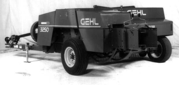
TOWING BALER (Fig. 94)

The Baler can be towed off the railcar or truck using chains attached to shipping stand at the locations shown.
Uncrating
The Baler Main Frame is shipped from the factory attached to a shipping stand. The various completing components, listed, are shipped either attached to the Baler Frame or the shipping stand.
Baler Drawbar
Lowering Baler Caution
Make sure chain is SECURELY fastened to the forklift and to the Baler.
Lowering Baler With Forklift

(Figs. 95 & 96)
NOTE: Contrary to what is shown in the pictures, it is advisable to remove everything that is banded or otherwise attached to the Shipping stand or Baler Main Frame BEFORE attempting to lower baler to the floor (or ground)

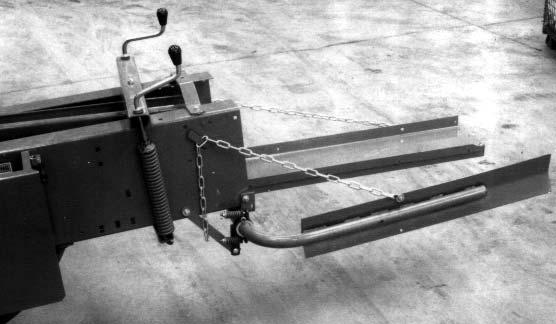
1.Attach a chain to the Baler Axle and fork frame. Chain must be slightly longer than forks to prevent damage to the pickup as the Baler is tilted toward the forks.
Caution
Make sure all personnel are in a safe position when lowering the Baler.
2.Back the forklift away from the Baler. As the Baler tilts over center, keep the forks raised close to the Baler tire for support.
3.Lower the Baler to the floor. After Baler is lowered, remove the chain and back the forklift away from the Baler.
Lowering Baler Using Gantry; Jib Crane or Hand Hoist (Figs. 97, 98 & 99)
NOTE: It is advisable to remove everything that is banded or otherwise attached to the Shipping stand or Baler Main Frame BEFORE attempting to lower baler to the floor (or ground)
1.Attach hook/chain through hole in Lifting Bracket located in Upper Packer Arm area.
NOTE: Keep chain loosely attached (NO tension) until Baler has been tipped to Position “2”.
Caution
NOTE: Space-out forks to cradle the Wheel as shown. Secure forks to prevent them from spreading.
prevent sliding
Ensure both ends of hoist are SECURELY fastened.
2.Using tractor with front end loader (or equivalent high-reaching, moveable, chain support), attach other end of chain around Baler axle, as shown. Pull in direction as shown until Baler is tipped off center. Remove chain from Baler axle.

Caution
Make sure all personnel are in a safe position when lowering the Baler.
3.Lower Baler to floor or ground. Disconnect hook/ chain from Baler.
NOTE: Lower the Baler on to the ground or floor with the shipping stand still attached as shown.
NOTE: Before separating the Baler from the shipping stand and with the right-hand Tire resting on the ground, steady the unit by placing approximately 12″(305 mm)high, wooden blocks, or a hydraulic jack, under the left-hand end of the Axle, as shown in Fig. 100. In addition, place wooden blocks or a jack under the Plunger Crank Housing.

Remove all of the banded parts from the shipping stand and then detach the stand from
Baler Assembly
Baler set-up should be performed inside an enclosed workshop which is equipped with the proper tools and an overhead hoist. Although the procedures imply a single set-up person, two people can and will be able to assemble the machine more quickly and easily.
Wheel Assembly (Figs. 100 & 101)
NOTE: For convenience, it is recommended that the following checks be made on the Baler BEFORE the left-hand Wheel assembly is installed: (a) Check that the Hook on the end of the Rod, shown in Fig. 101, is correctly aligned with the Pin on Needle Frame. (b) Check that Plunger Stop adjustment is correct per Adjustments chapter.

At the left-hand end of the Axle, remove the top Nut and Bolt. Insert the Hub Spindle into the hole in the end of the Axle and then reinstall Bolt, so it passes through the hole in the Hub Spindle. Reinstall and tighten the Nut to a torque of 60-70 ft-lb (81-95 Nm).
Install the Drawbar using the Special Attachment Bolt and Castellated Nut. Secure the Nut with 1/4
If the Wheel assembly is NOT already installed on the Hub, attach the Wheel using the Lug Nuts, provided. Tighten the Nuts to 90 ft-lb (122 Nm)


Drawbar and Hitchjack
(Figs. 102, 103, 104 & 105)
Install the Staybar through the Bale Chamber Bracket with the chamfered hole side facing up and the Stop Pin facing down. Connect the Staybar to the Drawbar using a Plain Washer and 1/4 x 1-/2″ Cotter Pin. Install a 1/2 x 1-/4″ Cap Screw, (head at top), Lock Washer and Nut, in the hole in Staybar closest to the Drawbar.
1 – Latch Lever
2 – Bolt & Nut Securing Latch to Housing
3 – Roll Pin
4 – Hole in Latch Pin

5 – Spring
6 – Plain Washer
7 – Cotter Pin
8 – Rope Attached to Latch Lever

NOTE: Fig. 104 and the following procedure are required ONLY if Latch assembly was NOT preassembled at the factory.
1.Assemble Latch Lever to lug on top of Latch Housing using Bolt and Nut.
2.Insert Roll Pin into the hole in Latch Pin and then insert Latch Pin into Housing through the hole in the top.
3.Slide spring and Plain Washer over end of Latch Pin and install Cotter Pin to secure Spring.
4.Attach Rope to Latch Lever.
5.Move Drawbar so Latch Pin engages one of the holes in the Staybar.
Install Hitchjack to the mounting Hub on the Drawbar and secure it with the Lock Pin. Adjust height of Jack to level and Support Drawbar.
The PTO Shaft and Flywheel center incorporates an Overrunning Mechanism so that, when the PTO Drive is disengaged on the tractor, the Baler PTO Shaft will also be disengaged while the remainder of the Baler Drives are coming to a stop.
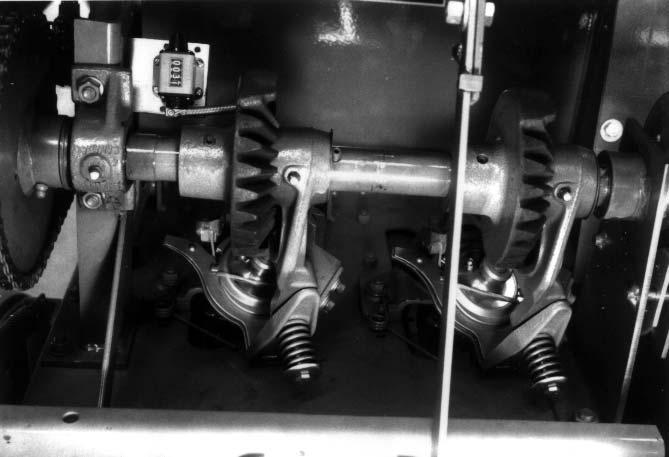
PTO Shaft Connection (Figs. 106 through 113)
Remove the Shield from the front of the Flywheel by partially rotating the Rear Shield to gain access to three Nuts. Remove the Nuts and then remove the Shield on front of Flywheel.


The Overrunning Mechanism consists of two Dogs each with a Spring installed at 180° to each other at the end of the Baler PTO Shaft. For reference, the Dogs are installed with the curved tip to the outside.

At the Universal Joint, at the end of the PTO Shaft, install Spring so the curve of the Spring follows the contour of the Groove in the Channel of the U-joint. Install the Dog, to rest on the Spring with the curved tip outwards.
Secure the dog using pawl pin (head of pin in recess at end of shaft, as shown). Secure pin with 3/32 x 3/4″ cotter pin.
NOTE: The Pawl Pin is a specially hardened Pin and NOT an ordinary Clevis Pin.

Install the other Spring and Dog using the same procedure.
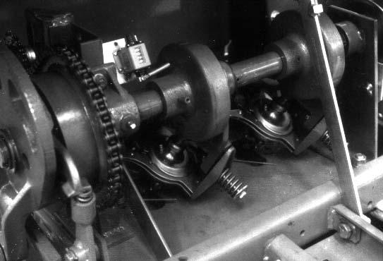
NOTE: The end of the PTO Shaft, with the Dogs, is installed into the center of the Flywheel and secured to Shaft by a Special Washer, Thrust Washer, and a Left-hand Threaded Cap Screw, as illustrated in Figs. 110 & 111.


Secure the PTO Shaft to the Flywheel Hub using Special Washer with Thrust Washer and Left-hand Threaded Cap Screw and tighten with 55 ft-lbs (75 Nm) torque.
NOTE: When correctly installed, Alignment Pin protruding from Special Washer (see Fig. 110), MUST be located in the Hole in the end of the Drive Shaft.
NOTE: Do NOT add Shims until after end play has been checked.
Insert the end of the PTO Shaft into the mating recess at the center of the Flywheel as shown. Rotate the PTO Shaft slightly clockwise to compress the Dogs into the Housing and allow the end of the Shaft to bottom-out inside the Clutch .
NOTE: The PTO Shaft must rotate freely when turned by hand in a clockwise direction (facing the Flywheel). If binding occurs, remove the PTO Shaft and remove any burrs or paint from the outer diameter of the PTO casting. Then, reassemble and recheck for smooth rotation.

Check End Play (Fig. 113)
NOTE: Before checking end play, make sure Shear Bolt is tight and that Shear Bolt Arm is tightened against both the Shaft Shoulder and the Flywheel.

Check end play of PTO Yoke. It should be 0.010to 0.030″. If in excess of 0.030″, it will be necessary to add Shims behind Yoke. Disassemble and add Shims, as required. If end play is less than 0.010″ , remove Flywheel and Shear Bolt Arm and remove any paint or dirt between the surfaces (0.010″ minimum end play MUST BE obtained BEFORE proceeding). Reassemble in reverse order of disassembly.
1 – Lower Half of PTO Support Bracket
2 – 3/4 x 7-1/8″ Headless Pin (2)
3 – Upper Half of PTO Support Bracket
4 – PTO Shaft Support, Clip and (1 each) 3/8 x 3/4 Cap Screw, Plain Washer and Nut
5 – Bearing Housing
6 – 7/16 x 7″ Cap Screw
7 – Bell Housing
8 – Drive Shield
9 – Cap Screws, Hardened Washers and Lock Nuts (Torque to 250-270 ft-lb)
Install the lower half of PTO Support Bracket to the Drawbar using a 3/4 x 7-1/8″ Headless Pin. Secure the Headless Pin with a 3/16 x 1-1/4″ Cotter Pin at each end.
Install the other 3/4 x 7-1/8″ Headless Pin in the top hole of the lower half of the PTO Support Bracket. Secure the Headless Pin with a 3/16 x 1-1/4″ Cotter Pin at each end.
Install the upper half of the Bracket to the lower half using a 1/2 x 2″ Cap Screw with a Special (hardened) 17/32 x 1-1/2 x 0.190″ thick Washer and Lock Nut. Secure the Lock Nut so that Bracket are free to pivot.
NOTE: The Stiffener Flange of each Bracket should be located toward the rear.
Install the Bearing Housing on the PTO Shaft with the Bearing and Snap Ring toward the front.
Reinstall and secure the Front Flywheel Shield.
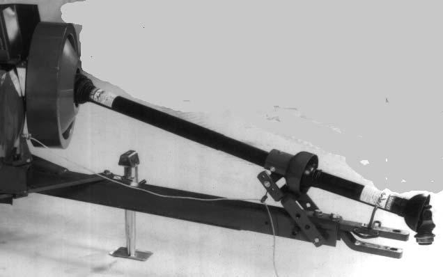
PTO Bearing Support (Fig. 114)
At the front of the Drawbar, install the Hitch Plates using (2 each) 3/4 x 3-3/4″ Cap Screws, Hardened Washers and Lock Nuts. Tighten Nuts to 250-270 ft-lb (340-365Nm). Refer to “Preparing for Field Operation” chapter for additional details.
Install the curved PTO Shaft Support using the Clip and a 3/8 x 3/4″ Cap Screw, Plain Washer and Hexagon Nut.
NOTE: The Bearing is a press-fit on the Shaft. When installing the Bearing make sure that only the Inner Race is used to press the Bearing onto the Shaft otherwise the Bearing can be damaged.
Install the Bearing Housing at the top of the upper Bracket using a 7/16 x 7″ Cap Screw; making sure that long Spacer is in mounting portion of Housing. Before installing the Nut, install the Rope Guide (Wire Loop) (NOT shown) over the Bolt and then install and tighten the Nut.
Install the Bell Housing over the Bearing Housing and secure with three Cap Screws and Lock Washers. Connect the Telescopic section of the rear PTO Shaft to the front PTO shaft and align the Set Screw with the recess in the PTO shaft. Tighten the Set Screw and Jam Nut to secure the Telescopic section.
Clearance Between Plunger and Bale Chamber Knives (Fig. 115) CAUTION

Use extreme caution when turning the Plunger, to check the clearance, since the Knives are very sharp. Under NO circumstances, should anyone attempt to insert their hand between the Knives (while they are separated by the Plunger stroke) .
NOTE: It is STRONGLY RECOMMENDED that clearance between the Plunger Knife and the Bale Chamber Knife be checked BEFORE the Bale Formers are installed. It is much more convenient to check (and adjust) the clearance at this stage than at any future time with the Bale Formers and Tension Rails installed. Check the clearance between the Plunger Knife and the Bale Chamber Knife along the entire length of the Knives. Clearance should be between 0.005″ and 0.030″
NOTE: For additional information of checking and adjusting the Plunger Knife and the Bale Chamber Knife clearance, refer to details in the “Shear Knife Adjustment” topic in the Service chapter.

Bale Formers and Tensioners (Figs. 116 through 123)
NOTE: In the assembly of the Bale Formers and related parts, the Carriage Bolts MUST be installed with their heads inside the Bale Chamber to ensure smooth passage of the bales through the Baler. Install the left-hand and right-hand Bale Formers to the end of the Bale Chamber using 3/8 x 1″ Carriage Bolts, Plain Washers and Nuts. Leave the Bolts of right-hand bale former loose until the Brace is installed. On the underside of the Bale Formers, install the Needle Guard using 3/8 x 1″ Carriage Bolts, Plain Washers and Nuts.
NOTE: Tighten the Nuts to take out the end play but allow the Tension Rail to pivot on the Bolts.
Install the upper Tension Rail at the upper Brackets, on the Bale using 1/2 x 1-1/2″ Cap Screws and Lock holes in Support Brackets, at both sides of the Bale Chamber.

NOTE: Tighten the nuts to take out the end play but allow the tension rail to pivot on the bolts.


Install Strap using 3/8 x 1″ Carriage Bolts in the last holes at the top of the Formers. Secure Cap Screws with Plain Washers and Lock Nuts.

Install the Tension Rail Support to the upper Tension Rail using a 1/2 x 5-3/4″ Carriage Bolt at the Tension Rail) secured with a Lock Nut.

Attach Springs to Cross Support and then insert the Tension Handles through the Support Rail and screw it into the Threaded Plugs at the top of the Springs.
Install the Metering Wheel and Shaft assembly to the top of the Bale Formers using 5/16 x 3/4″ Carriage Bolts, Plain Washers and Lock Nuts.
Install the Metering Arm on the Retaining Disc and connect the opposite end to the Knotter Clutch using the special Shoulder Bolt with a Plain Washer and secured with a Lock Nut, as shown in Fig. 120.

At the slotted holes in the Needle Guard, located directly under the Knotter assembly, install the three Ceramic Guides using the U-bolts supplied.
1 – Reset Cam on Clutch in Downward Position
2 – Metering Wheel
3 – Stop in Slot of Metering Arm

4 – 3/16 to 1/4″ (5 to 6 mm) Clearance Between Knurled Roller and Front Edge of Metering Arm
Fig. 122: Knurled Roller (Viewed with Outside Disc Removed)
NOTE: After the Shoulder Bolt, Plain Washer and Lock Nut are installed and the Lock Nut is tightly secured, the Metering Arm MUST fall freely and be centered between the Retaining Discs.
The Metering Wheel determines the length of the bales as they are being formed. Adjusting the Stop in the Slot of Metering Arm adjusts the length of the bales. To increase the length of the bales, move the Stop upwards in the Slot; to shorten the length of the bales, move the Stop downwards.

To ensure correct operation of the Metering Wheel, a clearance of 3/16” to 1/4” (5 to 6 mm) MUST be maintained between the front edge of the Metering Arm and the Knurled Roller at the center of the Disc assembly. This clearance is required through the full arc of Metering Arm when the Reset Cam on the Clutch is in the downward position.
The clearance can be obtained by adjusting the position of the Metering Wheel assembly by means of the slotted
Baler Shields & Miscellaneous Components (Figs. 124 thru 129)
At the Twinebox/Bale Chamber corner, install the right-hand Needle Guard Shield using (2 each) 5/16 x 3/4″ Carriage Bolts, Plain Washers and Lock Nuts and (2 each) 5/16 x 3/4″ Cap Screws, Plain Washers and Lock Nuts
1 2 2
At the left-hand side of the Baler, at the location of the Knotter assembly, install two Brackets for the left-hand Needle Guard Shield. Install Bracket at the second from top bolt at the Bale Chamber/Bale Former joint. Install Bracket using a 5/16 x 3/4″ Cap Screw in the pre-drilled hole in the Frame. Secure Screw with Plain Washer and Lock Nut.


1 – Knotter Assembly Shield

2 – 5/16 x 3/4 Cap Screws, Lock Washers & Nuts (2 Each of 5)
3 – Hinged Support Strap
4 – 3/16 x 15/16 Clevis Pin, Plain Washer & Cotter Pin
5 – Right-hand Bolt At Upper Tension Rail
Connect the Hinged Support Strap to the Shield using a 3/16 x 15/16″ Clevis Pin with a Plain Washer and Cotter Pin.
Install the Left Needle Guard Shield to the two Brackets using 5/16 x 3/4″ Carriage Bolts with Plain Washers and Lock Nuts. Secure the Shield to the Bale Former using two 5/16 x 3/4″ Carriage Bolts, Plain Washers and Lock Nuts.
Use the right-hand bolt at the Upper Tension Rail to attach the lower end of the Hinged Support Strap.
Install the Bracket to Swing Frame Shield for the Rubber Latch. Close the Knotter Shield and check the alignment with the Needle Guard Shield. Adjust the Needle Guard Shield, if necessary, to align the Shields.
NOTE: The Needle Guard Shield may require a slight adjustment to align with the Knotter assembly Shield when the latter Shield is installed.
Install the Knotter Assembly Shield using 5/16 x 3/4″ Cap Screws, Lock Washers and Nuts.

At the front of the Baler and in the area next to the Flywheel, install the Shield Latch using a 5/16 x 3/4 Cap Screw, Lock Washer and Nut. Using existing holes, attach the Shield Latch Anchor to the Front Shield with (2 each) 1/4 x 5/8 Cap Screws and Lock Nuts.

Plunger Crank Shield (Fig. 130)
The Plunger Crank Shield may be loosely installed in a forward location when the Baler is shipped. This Shield may have to be removed and relocated to its proper location as shown.

Gearbox Breather (Fig. 132)
NOTE: The Breather MUST be installed BEFORE the Baler is run with tractor PTO drive engaged.
Remove and discard the Square Shipping Plug in the Main Gearbox and install the Breather supplied .
Pickup Gauge Wheel (Fig. 131)
The Pickup Gauge Wheel may be inverted when the Baler is shipped. Remove the Pickup Gauge Wheel and reinstall it into its proper operating position, as shown.


SMV Emblem Mounting Bracket (See
Install the SMV Emblem Holder Bracket in the pre-drilled holes at the rear of the Packer Housing using (2 each) 1/4 x 5/8 Carriage Bolts, Plain Washers, Lock Washers and Nuts. If necessary, attach the SMV Bracket Holder to the Bracket with (2 each) 5/16 x 5/8 Carriage Bolts and Lock Nuts.
Slipping PTO Slip Clutch (Fig. 133)
Caution
To avoid possible damage as a result of Clutch seizure caused by lack of use, the Clutch should be slipped before a new machine is first put into operation and at the beginning of each season.
Caution
BEFORE proceeding to perform all Service routines on this unit, exercise the MANDATORY SAFETY SHUTDOWN PROCEDURE (page 8).
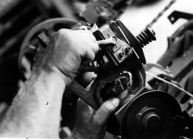
1.Loosen the Clutch Spring Nuts until 1/4″ (6 mm) of thread is showing.
2.To prevent Baler from turning while slipping the Clutch, engage the Plunger Stop as follows: a.With the Plunger at the front of the Baler, trip the Metering Mechanism. b.Rotate ONLY the Knotter Shaft 1/4 turn clockwise, to allow the Plunger Stop to move into the Bale Chamber. c.Rotate the Flywheel in the normal direction (counterclockwise when viewed from back of Baler) until the Plunger engages the Plunger stop.

3.Start the tractor and engage tractor PTO power and slip the Clutch for 10 to 20 seconds.
4. Exercise the Mandatory Safety Shutdown procedure, disengage the PTO and stop the tractor engine.
5.Rotate the Knotter Shaft back to the home position and reset the Metering Trip Arm.
To slip the Clutch:
6.Re-tighten Nuts, on the Clutch bolts until the shoulder is tight on the Pressure Plate. This completes the Slip Clutch “Slipping” process.