18 minute read
CHAPTER 9 SERVICE CAUTION

BEFORE proceeding to perform all Service routines on this unit, exercise the MANDATORY SAFETY SHUTDOWN PROCEDURE (page 8).
NOTE: The following information is referred to in both the Troubleshooting Guide and the Maintenance Schedule chapters of this manual. It should be understood that all services detailed in this chapter are Owner-Operator responsibilities. Where indicated, certain service routines should only be carried-out under the direction of an authorized GEHL equipment dealer.
This section covers items of servicing which are required periodically to keep Baler in good running order. These minor items can be done with ordinary tools. Where major servicing is required, consult your authorized GEHL Dealer.
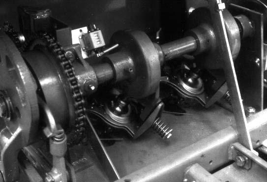
PTO YOKE END PLAY (Fig. 47)
The PTO Yoke should have an end play of 0.0l0 to 0.030″ (0.25 to 0.76 mm).
To check end play:
1.Make sure Shear Bolt Arm, 1, Fig. 47, is tight against the Shaft Shoulder, 2.
2.Check end play of PTO Yoke, if in excess of 0.030″ (0.76 mm), it is necessary to place Shims, 3, behind the Yoke. To install or remove shims: a.Remove Shield in the front of Flywheel. b.Rotate the Rear Shield to gain access to Shield Retaining Bolts. c.Remove Retaining Bolt, 4, (left–hand threads) Special Washer and Thrust Washer. d.Remove PTO Yoke and insert correct amount of Shims to obtain the 0.010 to .030″ (0.25 to 0.76 mm) end play. e.Reassemble Yoke, Thrust Washer and Special Washer (Pin in Washer MUST be aligned with Hole in Shaft). Tighten Bolt to 55 ft–lbs (75 Nm).
1 – Shear Bolt Arm
2 – Shaft Shoulder
3 – Shim(s)
4 – Left-hand Threaded Retaining Bolt, Special Washer & Thrust Washer
Fig. 47
After assembly, the PTO Yoke MUST be free to rotate (by hand) clockwise, when facing the Flywheel..
SURETIE KNOTTER TWINE KNIFE SHARPENING (Figs. 48, 49, 50 & 51)
The Twine Knife should always be razor sharp; especially the corner, which should be checked frequently to ensure it is NOT chipped.
If the knife becomes dull or the corner is chipped, it should be removed for resharpening.
Knife Removal
To remove the Knife:
1.Unlatch and open the Knotter Cover. Properly engage the Cover Support.
3.Rotate Knotter assembly upward until Bill Hook Roller, 1, Fig. 49, contacts back side of Cam, 2.

4.Lift Bill Hook Roller over Cam and continue rotating assembly until it is in a vertical position, as shown in Fig. 50.
5.Remove Cap Screw, 2, Fig. 51, and remove Knife, 1, from Locating Plate, 3.
NOTE: It is NOT necessary to loosen Socket Head Screws, 4, Fig. 51
Sharpening Knife
To sharpen the Twine Knife, proceed as follows:
1.Carefully maintain original cutting angle.
2.Remove the least amount of metal as possible from the cutting edge.

3.Take care so as NOT to overheat Knife.
4.Reinstall Knife onto Locating Plate, 3, Fig. 51, and secure with Cap Screw, 2.
5.Check and readjust the Twine Knife clearances per the following details, if necessary.

TWINE KNIFE CLEARANCES (Figs. 52 & 53)
Prior to checking and adjusting Twine Knife clearances, it will be necessary to trip Knotter Clutch and rotate Knotter Drive Shaft sufficiently to position the Bill Hook Roller, 2, Fig. 52 against Cam, 3. This ensures correct timing of Twine Disc.

Suretie Knotter
NOTE: If removal of complete Knotter is required, refer to the next topic titled “Removing Complete Knotter”.
NOTE: Either Knotter assembly can be serviced individually without removing Main Drive Shaft.
Disassembly (Figs. 54 through 71 and see Figs. 48, 49, 50 & 51)
1.Unlatch and open the Knotter Cover. Properly engage the Cover Support.
2.Remove Cap Screw, 1, Fig. 48, securing Knotter frame, 3, to bale chamber bracket, 2.
3.Rotate Knotter assembly upward until Bill Hook Roller, 1, Fig. 49, contacts back side of Cam, 2.
4.Lift Bill Hook Roller over Cam and continue rotating assembly until it is in a vertical position, as shown in Fig. 50.
5.Remove Pin from Bill Hook Gear, Fig. 54.
Check to ensure there is 0.060″ to 0.080″ (1.5 to 2 mm) overlap of Knife, 5 of Fig. 52. To obtain this overlap, remove the Socket Head Screws, 4, Fig. 51, and remove Shim(s) under the Locating Plate 3, Fig. 51.
Check to ensure there is 0.080″ to 0.120″ (2 to 3 mm) gap between Knife edge, 6, of Fig. 52, and Twine Disc, 4. Also, check to ensure there is 0.040″ to 0.050″ (1 to 1.25 mm) clearance between Knife, 1, Fig. 53, and the Twine Disc, 2, as indicated at 3,
To obtain these clearances, loosen the Socket Head Screws, 4, Fig. 51, and move the Locating Plate 3, Fig. 51, in the slotted holes. BE SURE the Socket Head Screws are securely retightened when adjustments have been completed.
54
6.Remove Cap Screw, 2, Fig. 51, securing Knife and remove Knife, 1.
NOTE: Do NOT loosen Socket Head Screws, 4, Fig. 51, as these secure a Plate set at factory to ensure correct relationships of Twine Knife to Twine Disc.

7.Using a screwdriver, pry tension arm, 3, Fig. 55, outward; then, turn cord grip, 2, to the left and remove it.

8.Remove two cap screws, 1, Fig. 55, securing assembly to frame. Remove bill hook and twine disc assembly.
9.Turn bill hook clockwise until roller contacts straight side of cam. Turn twine disc counter–clockwise to remove slack from planetary gears and then mark housing and twine disc, Fig. 56.


NOTE: Marking aids reassembly. If new parts are to be installed, marking is NOT required.
10.Loosen Set Screw in Retaining Collar, 3, Fig. 57, and slide Collar, Twine Disc, 2, and Twine Disc Cleaners off Bill Hook Shaft.
12.Make a tool, Fig. , to remove and install spring and pin in bill hook. Use as shown in Fig. 60.
Reassembly
13.Assemble Bill Hook parts, Fig. 61, holding Bill Hook, 1, with open end upwards.

14.Install pin, 5, Fig. 61, being sure pin is in notch in loose jaw; otherwise pin will be damaged.
15.Lubricate plug, 4, Fig. 61, with a small amount of grease and install it into bill hook bore with recessed end down.


16.Install spring.
17.Using the tool formed according to the details in FIg. 59, install spring retaining pin, 2, Fig. 61
NOTE: Be sure to reinstall Plastic Plug (NOT shown) in end of Bill Hook Shaft. This keeps dirt out of Spring area of Bill Hook.
18.Lubricate Bill Hook Bracket grooves (inside and outside) and Bearing and then install Bill Hook into Bracket.
19.Install Key in Bill Hook Shaft and install Sun Gear and Planetary Gears (with chamfers on Teeth upwards, as shown in Fig. 62).
20.Insert Twine Disc Cleaners, 1, Fig. 63, into grooves of Twine Disc.
When inserting Cleaners, ensure that flattened side, shown, Fig. 64, will be located adjacent to Knife when Knotter has been completely reassembled.
23.Install Bill Hook, 3, Fig. 66, and Twine Disc, 1, into Frame and Drive Gear.
24.Install Bolts, 2, Fig. 66, at rear of Housing to secure Bill Hook assembly into place. Do NOT tighten bolts at this time.
21.Referring to Fig. 63, turn Bill Hook until Roller contacts back side of Cam. Slide Twine Disc over Shaft and Twine Disc Cleaners over Pin. When Cleaners are correctly installed, they will be almost hidden behind Bracket.


NOTE: If new parts are installed, ensure Roller, 2, Fig. 52, on Bill Hook is against Cams, 3, and align Twine Disc, 4, so dimension 6, Fig. 52, is approximately 1/8″ (3 mm).
22.Install retaining collar and adjust end–play on shaft to obtain a 0.005″ (0.1 mm) clearance as indicated at ”1”, Fig. 65, and tighten set screw in collar, 2 of Fig. 63.

25.Rotate Bill Hook tip to point toward flat side of Drive Gear and align Pin hole.
26.Insert Pin.
27.Lift Twine Disc and Bill Hook assembly, 1 and 3, Fig. 66, by hand, so Bevel Gear contacts Knotter Frame, then tighten Bolts, 2 of Fig. 66.
NOTE: After tightening Bolts, 2, Fig. 66, ensure Bevel Gear and/or Bill Hook can be rotated freely, by hand.

28.Pry Cord grip tension arm, 5, Fig. 66 outward and insert cord grip, 4, into slots in twine disc, 1; then insert tab, 4, in slot of tension arm, 5.
NOTE: Bill Hook and Drive Gear are correctly timed when Knotter is bolted in place and Bill Hook points to left rear of machine.


29.Install Twine Knife on Locators and secure with Bolts, Fig. 67. Locators position Twine Knife correctly over Twine Disc.
NOTE: Locators and Plate are set at factory and secured to Bracket by the two Socket Head Screws.
1 – Dimension of 0.8 to 0.12″ (2 to 3 mm)
2 – Dimension of 0.06 to 0.08″ (1.5 to 2 mm)
3
0.04 to 0.05″ (1 to 1.3 mm)
After tightening the bolts, the twine knife should be positioned correctly. To check position, refer to dimension ”1”, ”2” and ”3” of Fig. 68.
If the dimensions ”1”, ”2” and ”3” of Fig. 68 are NOT obtained, loosen the Socket Head Screws and reposition the Knife and re-tighten the Screws. It may be necessary to add or remove Shims to obtain the dimensions.
31.Check distance between tip of Twine Disc Groove, 2, Fig. 70, and the Knotter Frame, 1, as indicated at ”3”. Distance should be 2.016″ to 2.040″ (51.2 to 51.8 mm).
REMOVAL AND INSTALLATION OF COMPLETE KNOTTER (See Figs. 33 & 23)
Removal
1.Disconnect Rod between Needle Swing Frame and Knotter Shaft, 5 of Fig. 33.
2.Remove Knotter Drive Chain, 2 of Fig. 33.
3.Remove Brake assembly, Fig. 23.
4.Remove Bolts (total of 5) securing Knotter to the Baler.
5.Remove complete Knotter assembly.
Installation
6.Reposition Knotter assembly on Baler and loosely attach with Bolts, removed in step 4.
7.Re-install Brake assembly, removed in step 3 and readjust tension per details under “Needle Brake” topic in Adjustments chapter.

NOTE: If the above dimension is NOT obtained, it may be necessary to add or remove Shims from the Main Shaft, 1, Fig. 69.
NOTE: The number of Shims required is determined by having a clearance of 0.005 to 0.015″ (0.13 to 0.38 mm) clearance between the Bevel Gear and the Pinion in the Knotter assembly.
32.Thread Knotter and check Cord Grip Tension Spring. If necessary, adjust Spring length to 1–1/2″ to 1–3/4″ (38 to 44 mm), Fig. 71.
8.Tightly secure hardware installed in step 6. Then, re-install Knotter Drive Chain and adjust tension with the Idler, 3 of Fig. 33. Check the Plunger to Needle timing per details under the “Timing” subtopic of the “Packer” topic in the Adjustments chapter..
9.Check the Needle adjustment and timing per details under the “Needles” topic in the Adjustments chapter.
SHEAR KNIFE SHARPENING (Fig. 72 & 73)
Warning
Use extreme caution when working with knives. Do NOT make contact with sharp edges.
The Plunger Knife, 1, Fig. 72, is mounted on leading edge of right–hand side of Plunger, and the Bale Chamber Knife, 2, Fig. 72, is mounted on right–hand side of Bale Chamber at rear of throat opening.
Knives MUST be sharp and properly adjusted to ensure good baling operation.
Position Plunger Knife midway in throat opening.
Warning
Disconnect Plunger Connecting Rod, 1, Fig. 73, from Drive Crank, 2, Fig. 73, to prevent unintentional movement of the Plunger.
NOTE: If Shims had been installed behind either Knife, make sure these are reinstalled in their original positions when Knife is reinstalled.
Remove Plunger Knife, 1, Fig. 72, by removing all three Countersunk Screws, 3, Fig. 72, with a 5/16″ allen wrench.
Continue Plunger movement until throat opening is completely clear and then remove Chamber Knife, 2, Fig. 72, by removing all three Countersunk Screws with a 5/16″ allen wrench.
Sharpen both Knives, maintaining original 45° angle and straight cutting edge.
NOTE: Make sure Knife does NOT get overheated during sharpening.
Lubricate threads and tapered area of the Countersunk Screws with Never–seize compound and reinstall Knives.

If Shims were removed, BE SURE they are reinstalled in their original positions.
PLUNGER KNIFE SUPPORT (Figs. 74 &
Plunger Knife Support, 2, Fig. 74, is located against Plunger Knife at location, 5, Fig. 75, and is used to prevent toe–in of Plunger Knife toward Bale Chamber. Where toe–in of Plunger is evident, support should be adjusted so that knife is parallel to Bale Chamber Knife. Adjustment is made by slightly loosening Bolts, 3, Fig. 74, and tapping Support, 2, so that support is adjusted in slotted holes. Make sure Bolts, 3, are tightened securely after adjustment has been made.
NOTE: Support is adjusted to ensure Plunger Knife is parallel to Bale Chamber Knife NOT to adjust Knife clearance.

SHEAR KNIFE ADJUSTMENT (Figs. 75, 76, 77 & 78)
1.Check operating clearance between Plunger Knife, 1, Fig. 75, and Bale Chamber Knife, 2.
To do this: a.Rotate Flywheel until Plunger Knife, 1, Fig 75, has just passed base of Bale Chamber Knife, 2, as shown, and check clearance using a feeler gauge. b.Rotate Flywheel until top of Plunger Knife is just past top of Bale Chamber Knife and again, check clearance. c.Clearances should be between 0.005″ to 0.030″ (0.1 to 0.7 mm) with same clearance at bottom and top of Knives.
Warning
Disconnect Plunger Connecting Rod, 1, Fig. 73, from Drive Crank, 2, Fig. 73, to prevent unintentional movement of the Plunger.
b.Position Plunger so Plunger Knife, 1, Fig. 75, is just passed top of Bale Chamber Knife, 2.
c.Loosen two rows of Nuts, 1, Fig. 76.
d.Adjust rear bolt, 2, Fig. 76, to raise or lower rail, 2, Fig. 77, until clearance between Plunger Knife and Bale Chamber Knife is same at top and bottom.
e.When Knife clearance is same top and bottom, adjust front bolt, 3, Fig. 76, so distance between lower Rail and Bale Chamber Floor is same at front and rear.

f.When lower Rail, 2, Fig. 77, is adjusted, tighten lower row of Nuts, 1, Fig. 76, so lower Rail is positioned securely.

g.Using upper row of Nuts, 1, Fig. 76, adjust top Rail, 1, Fig. 77, so there is a clearance of 0.015″ to 0.020″ (0.3 to 0.5 mm) between Plunger Roller, 3, and underside of top Rail, 1, along its full length.
2.If clearance is NOT the same at top and bottom, then Plunger is NOT parallel and MUST be readjusted.
To do this: a.Disconnect Plunger Connecting Rod, 1, Fig. 73, from Drive Crank, 2.
NOTE: Check to ensure both rows of nuts, 1, Fig. 76, have been tightened securely.
3.Where Knife clearance is the same at top and bottom, but the clearance exceeds 0.030″ (0.7 mm), the Knife clearance should be adjusted as follows: a.Position Plunger so the Plunger Knife, 1, Fig. 75, is just at the top of the Bale Chamber Knife, 2. b.Referring to Fig. 75, adjusting the position of the trapezoidal-shaped Rail, 4, laterally, adjusts the Knife clearance. The trapezoidal-shaped Rail, shown as 1, Fig. 78, is retained by a row of ten bolts with Nuts, 2, located on the underside of the Bale Chamber. c.Loosen ten nuts, 2, Fig. 78, on underside of Bale Chamber. d.At Locking Plate, 3, Fig. 78, tap the Nut so the bolt (and therefore the trapezoidalshaped Rail) moves in the slot to increase or decrease the Knife clearance; after the adjustment is made, tighten this Nut before checking the Knife clearance. e.The Knife clearance should be 0.005″ to 0.030″ (0.1 to 0.7 mm). When this clearance is obtained, reconnect the Plunger Connecting Rod, 1, Fig. 73, to the Drive Crank, 2. f.Rotate the Flywheel until the Plunger is at the front of the Bale Chamber. g.Adjust the trapezoidal-shaped Rail, 4, Fig. 75, until it is parallel with Guide Rail, 3, and then tighten the remaining nine Nuts. h.Recheck the Knife clearance to ensure it is 0.005″ to 0.030″ (0.1 to 0.7 mm).

NOTE: One of the bolts is located in a Locking Plate with a diagonal slot, 3, Fig. 78, which is retained by Block, 4. This arrangement allows the Rail to be tapped (by hitting the nuts) toward the rear of the Baler (in the direction of arrow ”5”) so the bolt is moved in the slot and the trapezoidalshaped Rail moves the Plunger Knife to effect its clearance to the Bale Chamber Knife.
BALE CHAMBER KNIFE DETAIL (Fig. 79)
Warning
Disconnect Plunger Connecting Rod, 1, Fig. 73, from Drive Crank, 2, Fig. 73, to prevent unintentional movement of the Plunger.
Whenever a new Bale Chamber Knife, 1, Fig. 79, is installed, it is important that the 0.003″ to 0.006″ (0.07 to 0.15 mm) clearance, as indicated at ”5”, Fig. 79, be re–established for the new Knife.
This clearance MUST exist between face of Bale Chamber Knife, 1, Fig. 79, and side of Guide Rail, 2, to ensure Plunger Knife, 4, does NOT contact Bale Chamber Knife when Baler is operating.
The 0.003″ to 0.006″ (0.07 to 0.15 mm) clearance can be obtained by using existing Shims, 3, Fig. 79, and where necessary, adding Shims, supplied with Baler from factory. When this clearance is obtained, reconnect the Plunger Connecting Rod, 1, Fig. 73, to the Drive Crank, 2.
After a new Knife has been installed, turn Flywheel by hand to ensure Plunger Knife is clear of Bale Chamber Knife. Also, recheck Knife clearance as detailed under “Shear Knife Adjustment” topic in the Adjustments chapter and re-adjust, if necessary.
2.Remove Chains from solvent and allow to drain.
3.Completely immerse Chains in SAE 30 motor oil and allow to soak as long as possible, preferably overnight.
4.Remove from oil and suspend Chain to allow surplus oil to drain off. Wipe chain with clean cloth.
NOTE: Chain MUST be allowed to drain thoroughly.
MAIN GEAR HOUSING (Fig. 80)

Drive Chains
NOTE: The following procedure is recommended if a Drive Chain becomes stiff.
1.Remove Chains from Baler, coil each one and completely immerse in kerosene or similar solvent. To speed cleaning process, work links backwards and forwards to help solvent to penetrate.
If at any time, the Main Gear Housing has been drained of oil, the following procedure MUST be used for refilling:
1.Make sure that the Drain Plug is replaced and tightened.
2.Fill Housing through Oil Level Plug with EP80W90 Gear Lube until it just begins to run out of Level Plug Hole. Then, wipe up any surplus oil and reinstall the Plug, The Housing requires 1 U.S. quart (0.95 liters) of EP80W90 Lube. Order and obtain 1 Quart Bottle by Gehl Part Number 127178).
NOTE: Do NOT overfill the Housing.
SLIPPING PTO SLIP CLUTCH (Fig. 81)
To avoid possible damage as a result of Clutch seizure caused by lack of use, the Clutch should be slipped before a new machine is first put into operation and at the beginning of each season.

operation. The Left 11L-15 Tire, on the 3210 model Baler, should be inflated to 25 PSIG (155 kPa) or, on the 3250 model Baler, should be inflated to 32 PSIG (224 kPa). The Right 27 x 9.50-15 Tire on either model Baler should be inflated to 15 PSIG (105 kPa).
NOTE: If a Bale Thrower Attachment is installed the Left Tire pressure should be increase to 36 PSIG (252 kPa).
Wheel Lugs torque should also be checked after every 50 hours of operation and tightened with 90 ft-lb (124 Nm) torque.

Warning
Inflating or servicing tires can be dangerous. Whenever possible, trained personnel should be called to service and/or mount tires. In addition, do NOT place your fingers on the tire bead or rim during inflation; serious injury or amputation could result. In any event, to avoid possible death or serious injury, follow the safety precautions below:
NOTE: Refer to the “Slipping PTO Slip Clutch” topic in the Set-up & Assembly chapter for details.
HAY CHECKS (Fig. 82)
After every 10 hours of operation or daily, remove all crop material from beneath the top and bottom Hay Checks, as necessary. Debris can affect bale shape and tying performance.
• BE SURE the Rim is clean and free of rust.
• Lubricate both the tire beads and rim flanges with a soap solution. Do NOT use oil or grease.
• Use a clip-on tire chuck with a remote hose and gauge which allows you to stand clear of the tire while inflating it.
• NEVER inflate beyond 35 PSI (240 kPa) to seat the beads. If the beads have NOT seated by the time the pressure reaches 35 PSI, deflate the assembly, reposition the tire on the rim, relubricate both parts and re-inflate it. Inflation pressure beyond 35 PSI with unseated beads may break the bead or rim with explosive force sufficient to cause death or serious injury.
• After seating the beads, adjust the inflation pressure to the recommended operating pressure listed.
TIRES & WHEELS
Check the Tire pressure after every 50 hours of
• Do NOT weld, braze, or otherwise attempt to repair and use a damaged rim.
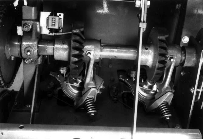
OVERRUNNING CLUTCHES (Figs. 83 & 84)
ing, after the drive force is removed. NO field adjustment is required under normal conditions. The function of both Clutch assemblies should be tested after every 500 hours of service or at least once a year.
Overrunning Clutches are provided on both the PTO Drive Input connection to the Baler and the Pickup Drive connection. Both Clutches are designed to help prevent Drive Line damage by allowing for free-wheel-

Chapter 10 Preparing For Field Operation
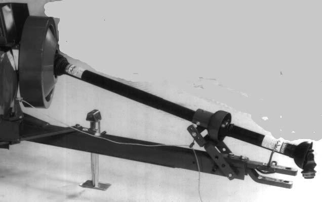
TRACTOR DRAWBAR & PTO SHAFT REQUIREMENTS (Fig. 85)
The tractor MUST be equipped with drawbar and PTO shaft conforming to ASAE standard S203, as shown.
Caution
Do NOT allow anyone to ride on any part of the Baler when it is in motion.
Turning Corners
NOTE: DO NOT turn corners too sharply as this places excessive stress of the PTO drive shaft and may cause damage to drive components.
ATTACHING BALER TO TRACTOR (Fig. 86)
Rotate the Hitchjack Handle to lower or raise Baler Drawbar until the Baler is level.
1 – 14″ (355 mm)
2 – 6 to 12″ (150 to 300 mm)*
3 – 13 to 17″ (330 to 432 mm)*
4 – Tractor PTO Shaft*
5 – Tractor Drawbar*
6 – Locking Hitchpin
7 – Upper & Lower Bearing Support Yokes
*Tractor MUST comply with ASAE Standard S203 Fig. 85
Tractor Horsepower
The minimum power required to operate the Baler is 30 horsepower.
Baler Operating Speed
The Baler MUST be operated with tractor PTO speed of 540 RPM. This provides a Plunger operating speed on the Baler 80 strokes per minute.
Tractor Ground Speed
The ground speed of the tractor MUST be regulated to suit both crop and ground conditions to ensure bales will be properly formed and tied.
Fig. 86: Possible Hitch Plate Positions
Back the tractor toward Baler and check the alignment of the Hitch.
If Hitch is NOT in alignment (when Baler is level), reposition Hitch Plates to closest one of the four positions shown.
NOTE: If Hitch Plates are repositioned, the mounting Bolts MUST be tightened to a torque of 190 to 210 ft–lbs (257 to 285 Nm).
When Hitch is aligned, connect Hitch to tractor drawbar using a locking hitchpin. Attach PTO Shaft Coupler to tractor PTO shaft by pulling back the Slide Lock and sliding the Coupling onto PTO shaft. Make sure locking ball engages shaft when Slip Lock Ring is released.
When Baler PTO Shaft is attached to tractor, the two sections of the PTO Shaft should be in a straight line when viewed from the side of the PTO Shaft. If NOT, adjust Upper and/or Lower PTO Bearing Support Yokes, to obtain the correct alignment.
Refer to the “Twine & Threading” topic in the Operation chapter for procedures to follow for threading twine.
If the Baler is equipped with an optional Bale Thrower, connect the Thrower Electrical Harness per details in the separate Thrower Manual provided.
Place the Hitchjack in the “Storage” position.
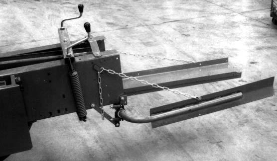
DRAWBAR OPERATING AND TRANSPORT POSITIONS (Figs. 87 & 88)
The Drawbar can be engaged in one of two positions by anchoring the Latch Pin into one of the two holes in Stay Bar.
The “Field Operating” position is the one where the Latch Pin is engaged in the outer hole of Stay Bar.
The “Transport” position (for towing the Baler) is with the Latch Pin is engaged in the inner hole of Stay Bar.

Transport–to–Operating Position
1.Slowly move tractor forward.
2.Pull on Drawbar Control Rope to disengage Spring–loaded Latch Pin.

3.As tractor moves forward, release the Rope and allow the Latch Pin to automatically engage the hole to lock the Drawbar.
Operating–to–Transport Position
4.Slowly move tractor rearward.
5.Pull on Drawbar Control Rope to release the Spring–loaded Latch Pin.
6.As tractor moves rearward, release the Rope and allow the Latch Pin to automatically engage the hole to lock the Drawbar.
Chapter 11 Transporting
METERING ARM TRANSPORT LOCK (Fig. 89)

Warning
You may become entangled in moving components. Install the Transport Lock BEFORE threading the Needles or transporting the machine. Lock prevents the Metering Arm from engaging the Knotter cycle. Failure to heed could result in death or serious injury.
Emblem Mounting Bracket mounted to the back of the large top Shield; the SMV Emblem MUST be purchased locally. Because of variations in safety laws for different states and localities, it may be necessary to use a different location for displaying the Slow-moving Emblem. Your Gehl Dealer can aid you in installing a different Emblem Mounting Bracket (if required). Red Reflector Strips are provided at the rear corners of the Baler and Amber Reflector Strips are provided at the front corner of the Baler, as shown.
The Baler is provided with a Metering Arm Lock to lock the position of the Arm to prevent it from activating the Knotter cycle.
NOTE: After the Baler is transported and before starting to bale, BE SURE to de-activate the Lock.
SMV EMBLEM & REFLECTORS (Figs. 90 & 91)
The Baler is provided with a Slow-moving Vehicle


As required or when desired, the Baler can be equipped with a Safety Chain for operation on public highways. The Safety Chain, when attached in this manner, has the following characteristics:

1.Chain is sufficiently slack to allow turns and movements of either the tractor or the farm implement, without placing tension on Chain.
2.Chain is of sufficient strength to hold the decoupled implement (and its load) and tow it to the shoulder.
Caution
ALWAYS follow state and local regulations regarding use of a safety chain and auxiliary lighting when towing farm equipment on public highways. ONLY a safety chain (NOT an elastic or nylon/plastic tow strap) should be used to retain the connection between the towing and towed machines, in the event of separation of the primary attaching system. BE SURE to check with local law enforcement agencies for your own particular regulations. Unless otherwise prohibited, use a Slow-moving Vehicle Emblem. NEVER tow a Baler on a public highway at a speed greater than 20 mph (32 kmh). BE SURE the Metering Arm Transport Lock is properly engaged, before transporting the Baler.