73 minute read
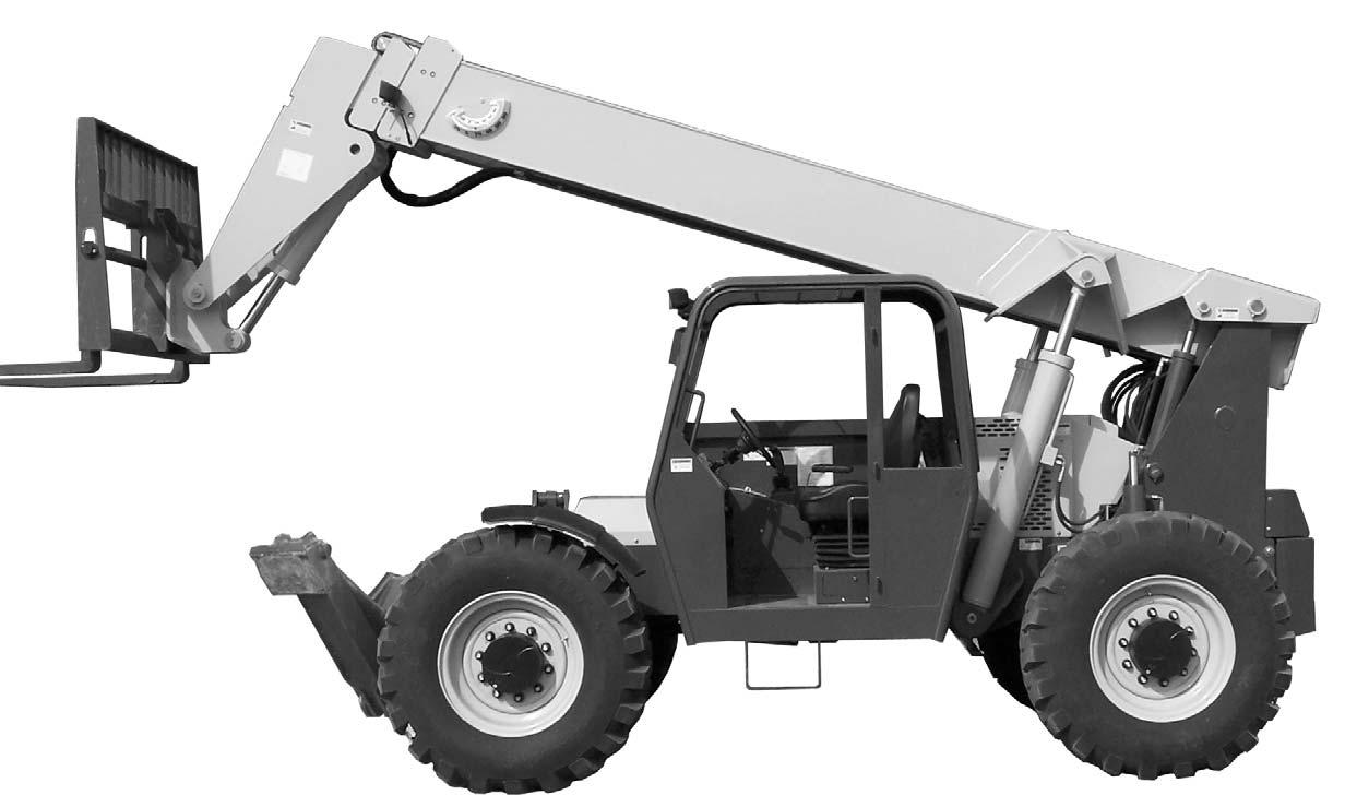
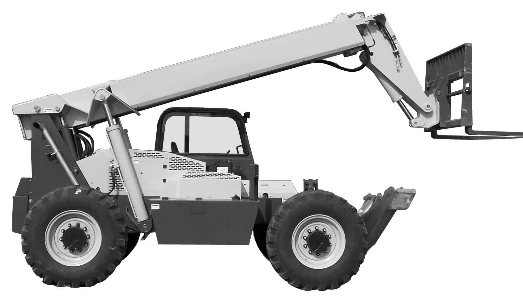
Pre-Start Walk-Around Inspection Illustration

from Gehl RS6-42 GEN2 RS8-42 44 GEN2 RS9-50 GEN2 RS10-44 55 GEN2 RS12-42 GEN2 Handler Operator's Manual

PRE-START WALK-AROUND INSPECTION PROCEDURE
Refer to the following illustration and checklist to perform the inspection. Begin with item 1 at the left front of the machine and walk toward the rear of the machine on the left side and around the back and toward the front on the right side of the machine.
Any needed repairs or service noted during the inspection must be performed by a qualified service technician before operating the machine.
The illustration and checklist page can be copied for future pre-start walk-around inspections.
Pre-Start Walk-Around Inspection Checklist
Note the condition of safety decals during the walk-around inspection. Replace missing or illegible safety decals.
o1.Attachment Tool: Check for broken, missing or damaged parts. When using a personnel work platform, check to see if the platform meets ANSI/ITSDF standards and that it is secured to the forks and fork carriage. When using forks, check for welds, cracks or misalignment. Replace the forks in sets when the condition of the forks is questionable.
IMPORTANT: DO NOT use forks that have been repaired by welding.
o2.Attachment Tool Mount: No loose or missing parts; no visible damage.
o3.Attachment Tool Mounting Pins: No visible damage; pin fit is secure and properly lubricated.
o4.Boom Chain: No loose or missing parts; no visible damage; sheave pin fit is secure and properly lubricated.
o5.Boom Sections and Wear Pads: No loose or missing parts; no visible damage or excessive wear.
NOTE: Wear pads that measure 3/8” (9.5 mm) thick or less need to be replaced.
o6.Outriggers (when equipped): Properly secured; pads in downward position; no visible damage; no loose or missing parts; no leaking from the cylinder.
o7.Boom Angle Indicator: Properly secured; no visible damage; bubble is visible.
o8.Tire and Wheel Assemblies: Properly secured; no loose or missing lug nuts; no visible tire damage (cuts or abrasions); proper inflation.
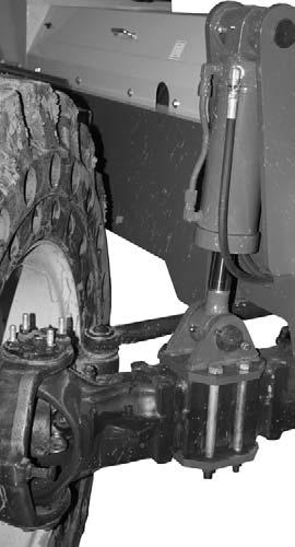
o9.Front and Rear Axles: No loose or missing parts; no visible damage; tie rod end studs locked; no evidence of leaking; properly lubricated.
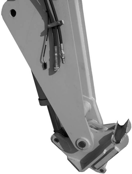
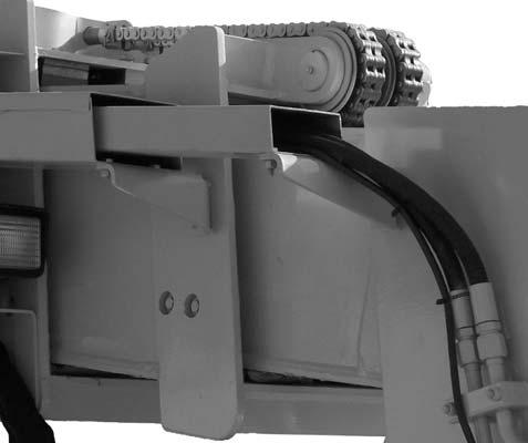
o10.Operator Compartment: o Seat belt undamaged; operates properly; mounting hardware secure. o Switches and levers undamage; o no loose or missing parts; o load charts properly secured and legible; o levers and switches operate properly; control markings legible; o frame level indicator secured and undamaged, bubble is visible. o11.Lift Cylinder: Properly secured; no visible damage; no evidence of leaking from the cylinder; properly lubricated. o12.Rear Axle Stabilizer Cylinder: Properly secured; no visible damage; no evidence of leaking from the cylinder; properly lubricated. o13.Slave Cylinder: Properly secured; no visible damage; no evidence of leaking from the cylinder; properly lubricated. o14.Stabilizer Switch: Properly secured; no visible damage; no loose or disconnected wires. o15.Boom Pivot Assembly: Properly secured; no visible damage or excessive wear; properly lubricated. o16.Boom Hydraulic Hoses: No visible damage or exterior wear; no evidence of leaking. o17.Rear Light Assembly: Properly secured; no visible damage; no loose or disconnected wires; no malfunctions. o18.Hydraulic Control Valve Assembly: No loose or missing parts; no evidence of leaking; no damaged or leaking hoses. o19.Exhaust System: No loose or missing parts; no visible damage; no obstructions to the outlet. o20.Hydraulic Cooler: No loose or missing parts; no visible damage; no evidence of leaking; cleanliness; o21.Engine Compartment: o Engine oil level, add if needed; o Coolant level, add if needed; o No evidence of engine oil or coolant leaks; o Belts and hoses in good condition, properly secured and adjusted o22.Boom Hose Guards: Properly secured; no visible damage. o23.Engine Air Filter: No loose or missing parts; no visible damage; no obstructions to the evacuator; precleaner free from dirt; restriction indicator proper reading. o24.Battery Compartment: Proper electrolyte level; no loose or damaged cables; no visible damage or corrosion. o25.Fuel Tank: No visible damage; no evidence of leaking; level of fuel; breather cap secure and working. o26.Mirror Assembly: No loose or missing parts; no visible damage; properly adjusted. o27.Hydraulic Oil Reservoir: No visible damage; no evidence of leaking; recommended oil level; breather cap secure and working. o28.Cowling and Latches: All cowling, doors and latches in working condition; properly secure; no loose or missing parts; all components operate properly. o29.Frame Tilt Cylinder: Properly secured; no evidence of leaking; properly lubricated. o30.Frame: No visible damage; no cracked welds; no loose or missing parts. o31.Tilt and Auxiliary Hydraulic Hoses: No visible damage or excessive wear; no evidence of leaking. o32.Attachment Tilt Cylinder: Properly secured; no visible damage; no evidence of leaking from the cylinder; properly lubricated.
Date:_________________Initials:_______________
Before Starting Engine
Before mounting the operator’s compartment, walk completely around the machine to be sure no one is under, on, or close to it. Let others in the area know you are going to start up. Wait until everyone is clear of the machine before starting it up.
Before starting the engine and running the machine, refer to the Indicators and Controls chapter and become familiar with the various operating controls, indicators and safety features.
Starting The Engine
Warning
ALWAYS fasten the seat belt BEFORE starting the engine. Leave the parking brake applied until the engine is running and you are ready to operate the machine.
The following procedure is recommended for starting the engine:
1.Grasp the handholds and step up into the operator’s compartment.
2.Adjust the seat and fasten the seatbelt.
3.Check that all controls are in their “neutral” positions, except the parking brake switch, which should be in the “ON” position.
4.Turn the key switch clockwise one position to the “ON” position. When the wait-to-start indicator lamp in the multi-function display goes out, the engine can be started.
NOTE: The lower the ambient temperature the longer the wait-to-start indicator lamp will remain illuminated. Wait for the indicator lamp to go out before attempting to start the engine.
5.Turn the key switch clockwise until the engine starter activates. Release the key switch when the engine starts. If the key switch is released before the engine starts, turn the key switch to the “OFF” position and wait one minute before attempting to start again.
IMPORTANT: The engine is equipped with a starting motor protection feature. If the engine fails to start within 30 seconds, the engine starter will stop operating and the wait-to-start lamp will flash for 2 minutes allowing the starter to cool. DO NOT turn the ignition switch to “OFF” until the wait-to-start lamp stops flashing. When the waitto-start lamp stops flashing turn the ignition key to “OFF” then back “ON”, when the wait-to-start lamp goes out, the engine can be started.
6.After the engine starts, allow 3 to 5 minutes before operating the machine with a load.
7.Check that indicators are in their normal operating conditions.
8.Verify that there are no fuel, oil or engine coolant leaks, and no abnormal noises or vibrations.
Cold Starting Procedures
The engine is equipped with a intake air heater for starting the engine in temperatures down to 0°F (-18°C) and a block heater for starting the engine in temperatures below 0°F (-18°C).
Warning
DO NOT use starting fluid on engines equipped with an intake air heater. Starting fluid is highly flammable and may explode, causing serious injury.
The following procedure is recommended for starting the engine in temperatures below 0°F (-18°C):
1.Plug the engine block heater in at least one hour before attempting to start the engine.
2.Follow the steps 1 - 8 listed in “Starting The Engine”.
If the battery becomes discharged and has insufficient power to start the engine, jumper cables can be used for starting assistance. Refer to the jump starting instructions in the Service and Storage chapter of this manual for safe jump starting procedures.
Stopping
The following procedure is the recommended sequence for stopping the machine:
1.Bring the machine to a stop on a level surface. Avoid parking on a slope, but if necessary park across the slope and block the wheels.
2.Fully retract the boom and lower the attachment to the ground.
3.Idle the engine for at least 3 minutes for gradual cooling.
IMPORTANT: If an Exhaust Filter Cleaning has just been performed, increase the engine idle time to 5 minutes.
4.Place controls in neutral. Apply the parking brake.
5.Turn the ignition switch key to the “OFF” position. Remove the key.
6.Unfasten the seatbelt, and grasp the handholds while climbing out of the operator’s compartment.
First Time Operation
Make sure the engine is warm, and then go through the following procedures:
Caution
Be sure the area used for test-running is clear of spectators and obstructions. Initially, operate the machine with an empty attachment tool.
Place the travel lever in Forward or Reverse and select a speed range. Switch off the parking brake and move ahead slowly, while testing the steering and brakes. Stop and operate all boom, attachment tool functions and frame leveling controls, checking for smooth response.
Apply the service brakes, stop the machine and move the travel lever to the opposite direction.
Shifting to the next higher gear may be done at any engine speed while the machine is in motion.
DO NOT overspeed the engine when down-shifting. Allow the machine to slow down before shifting to the next lower gear.
Engine Protection System
The engine is equipped with an engine protection system. The system monitors critical engine temperatures and pressures, and logs diagnostic faults when an over or under normal condition occurs. If an out-of-range condition exists and the engine derate action is to be initiated, the operator is alerted by the amber Check
Engine Warning lamp. The red Engine Stop lamp flashes when out-of-range conditions continue to worsen. The operator must shut down the engine as soon as it is safe to do so.
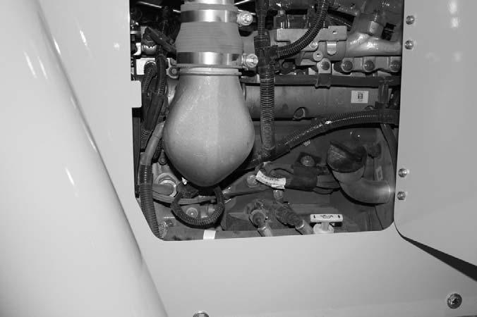
Exhaust Filter Cleaning System
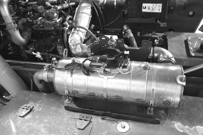
The engine is equipped with a Selective Catalytic Reduction (SCR) system in place of a muffler. The SCR is located under a cover to the right of the engine as shown below with covers removed. The SCR uses diesel exhaust fluid (DEF) to reduce the nitrogen oxide emissions from the exhaust into nitrogen and water.
Under normal machine operation and with the system in AUTO mode, the SCR system requires minimal operator interaction.
Selective Catalytic Reduction (SCR)
To avoid unnecessary buildup of diesel particles or soot in the exhaust filter system;
1.Utilize the Automatic (AUTO) Exhaust Filter Cleaning mode.
2.Avoid unnecessary idling.
3.Use the proper engine oil. See Lubrication chapter of this manual or the engine maual for proper engine oil specifications.
4.Use only ultra low sulfur diesel (ULSD) fuel. See Lubrication chapter of this maual or the engine manual for fuel requirements.
Automatic (AUTO) Exhaust Filter Cleaning
Operating the engine in AUTO Mode allows the ECU to perform intelligent exhaust cleaning as required. The High Exhaust System Temperature (HEST) Lamp will illuminate when the system is actively performing an exhaust filter cleaning. When the exhaust filter cleaning process has completed its cycle, the (HEST) indicator will turn off.
The machine can be operated as normal during the auto exhaust filter cleaning process unless the operator determines the machine is not in a safe location for high exhaust temperatures and disables the auto cleaning process.
To disable the auto exhaust filter cleaning mode, press the Disable Auto Exhaust Filter Cleaning button.
IMPORTANT: It is recommended that the exhaust filter cleaning be in the Auto mode at all times. Auto mode should only be disabled when the machine is not in a safe location for high exhaust temperatures.
If the machine is not able to be moved to a safe location, the operator should temporarily disable auto exhaust filter cleaning. If the machine is located in a safe location, the auto mode should always be enabled.
Stationary Exhaust Filter Cleaning
Stationary exhaust filter cleaning is initiated by the operator. This process allows the system to clean the SCR when the operator previously needed to disable the auto exhaust cleaning process because of specific conditions.
When a stationary exhaust cleaning is initiated by pressing the Exhaust Filter Cleaning button, the Exhaust System Cleaning Lamp will flash indicating the exhaust cleaning is in process. During this process the engine speed will be controlled by the ECU. The machine must remain parked during this process.
Warning
During auto or manual exhaust filter cleaning operations, the engine will run at elevated idle and hot temperatures for approximately 30 minutes. Exhaust gases and exhaust components reach temperatures hot enough to burn people, ignite, or melt common materials.
Servicing the machine or attachments during exhaust filter cleaning can result in serious personal injury. Avoid exposure and skin contact with hot exhaust gases and components.
If the machine is not in a safe location for elevated temperatures, move the machine to a safe location and check for adequate fuel level before beginning the exhaust filter cleaning process.
NOTE: It is not necessary to perform a stationary exhaust cleaning unless a previous auto cleaning process was cancelled and the Exhaust System Cleaning indicator is illuminated.
Cleaning times will vary depending upon several specific criteria. The average standard cleaning time can range from 20 - 50 minutes or longer.
To enable a stationary exhaust system cleaning;
1.Park the machine in a safe location away from any combustible surface, and check that the machine has a recommended 1/4 tank of fuel to complete the process.
2.Apply the park brake, and place the transmissionin neutral.
3.With the engine running at idle, press the Exhaust System Cleaning button. The engine speed may increase, the High Exhaust System Temperature (HEST) Lamp may illuminate and the Exhaust System Cleaning Lamp will flash.
4.Monitor the machine and surrounding areas for safety. If the machine needs to be used or moved before the exhaust cleaning is completed, stop the stationary cleaning by pressing the Disable Exhaust System Cleaning button.
5.When the Exhaust System Cleaning is complete, the engine will return to idle speed and the (HEST) and Exhaust System Cleaning Lamp will turn off.
If the machine is not going to be returned to service immediately after the cleaning process, allow the engine and the exhaust filter time to return to normal operating temperature before stopping the engine. The stationary exhaust filter cleaning process can be canceled at any time during the process.
Avoid disabling the cleaning process unless absolutely necessary. Repeated disabling or ignoring prompts to perform a stationary cleaning procedure will cause additional engine power limitations.
Utilize AUTO Exhaust Filter Cleaning mode to avoid additional service.
Disable Exhaust Filter Cleaning
This indicator lamp will be illuminated when the Disable Exhaust Filter Cleaning button has been pressed. When illuminated, an automatic or stationary exhaust system cleaning can not occur. Disabling the exhaust system cleaning is not recommended. Disable the automatic exhaust system cleaning only when high exhaust temperature presents a hazard. Whenever possible, cleaning should be allowed and the exhaust system cleaning button should be left in the AUTO Mode. When left in auto mode, soot buildup in the exhaust filter system will be at a minimum.
Exhaust Filter Cleaning Precautions
When the AUTO Exhaust Filter Cleaning is disabled, the sytem has 2 levels of notification to advise the operator to perform the exhaust filter cleaning. The 2 levels are as follows;
1.The Exhaust System Cleaning Lamp will illuminate, indicating that the exhaust system needs to be cleaned at the next opportunity. If conditions are safe, the operator should enable auto exhaust filter cleaning or perform a manual exhaust filter cleaning.
2.If an Exhaust System Cleaning is not performed in a timely manner after the Exhaust Cleaning Lamp is illuminated, the Check Engine Lamp will illuminate, and engine power will be significantly reduced. If conditions are safe, the operator should enable auto exhaust filter cleaning. If conditions are not safe, the operator should move the machine to a safe location and perform a stationary exhaust filter cleaning.
Diesel Exhaust Fluid (DEF) Precautions
An illuminated DEF lamp indicates the DEF level is low. The DEF lamp flashes when the DEF level is very low. Fill the DEF tank completely with DEF in order to correct any fault conditions.
When the DEF lamp is flashing and the Check Engine Lamp is illuminated, the DEF level is critically low. If the DEF tank is not filled with DEF immediately, power will be reduced.
When the DEF lamp is flashing and the Stop Engine Lamp is illuminated, the DEF gauge reads zero. If the DEF tank is not filled with DEF immediately, power will be further reduced or limited to idle.
NOTE: It is recommended that the DEF tank be filled in order to correct any fault conditions. DO NOT overfill DEF tank especially in freezing temperatures.
Parking Brake
NOTE: The parking brake mechanism within the front axle is not designed for, and not intended to be used as, the primary means of stopping movement of the machine. Hydraulic braking provided through the service brakes within the axles is the primary means for stopping movement. The axleby-axle split brake system is the secondary means of stopping movement.
The proper sequence for correct machine operation is to always engage the parking brake switch before shutting off the engine; and to disengage the parking brake ONLY after the engine is running. In an EMERGENCY, if it becomes necessary to STOP movement, activate the parking brake switch to “ON.”
Changing Attachment Tools
The Telescopic Handler boom nose will accept Quickattach System Gehl attachment tools. The Quick-attach System has a quick-release hookup and locking mechanism for mounting framing-type or masonry-type attachment tools to the boom nose.
Attaching Procedure
To pick up the attachment tool proceed as follows:
1.Raise the boom slightly, extend it two to three feet (600 to 900 mm) for better visibility, and tilt the Quick-attach System forward.
2.Align the Quick-attach System squarely with the back of the attachment tool.
3.Slowly extend the Quick-attach System and lower the hook under the attachment tool hookup bar.
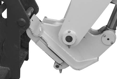
4.Tilt the Quick-attach System back so that the lock plate engages the attachment tool as shown below. This secures the attachment tool to the Quick-Attach system. Verify the attachment tool is properly secured by tilting the tool sufficiently forward such that it does not hinge away from the tool carrier.
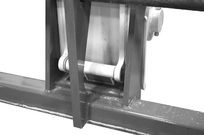
Attachment Tool
Locked to Quick-attach System
Quick-attach System Attaching Detail
5.For an attachment tool with auxiliary hydraulics, connect the hoses to the quick-disconnect connectors on the boom nose.
Detaching Procedure
To detach attachment tool, proceed as follows:
1.Raise the boom slightly and extend it two to three feet (600 to 900 mm) for better visibility. Lower the boom until the attachment tool is approximately 12” (0.3 m) off the ground.
2.Tilt the carrier rearward as far as it will go. Once the carrier is tilted back all the way, perform the Mandatory Safety Shutdown Procedure (p. 9, Safety chapter).
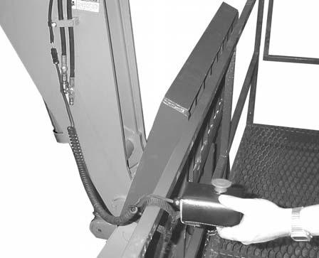
3.With the engine off, leave the operator’s station. Manually raise the lock spring and flip the lock plate up and outward at least 180° as shown below so it is in position to re-lock on the next attachment tool.
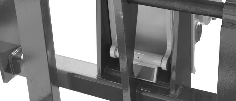
4.Tilt the Quick-attach System forward to allow the attachment tool to roll out, then lower the boom so the hook ears clear the hookup bar on the attachment tool.
NOTE: One side of the lock plate has a bright red decal to indicate the unlocked position.
5.If the attachment tool has auxiliary hydraulics, disconnect the hoses from the quick-disconnects on the boom nose.
6.Start the engine and tilt the Quick-attach System forward, then slowly back the machine until the attachment tool is free from the boom nose.
Warning
Modifications, alterations to, or use of attachment tools NOT authorized by GEHL (or the manufacturer) in writing can void warranty and cause machine damage and/or serious personal injury or death.
SELF-LEVELING
The machine is equipped with a hydraulic self-leveling feature. This feature is designed to keep the attachment tool level while the boom is being raised or lowered.
Machine Operation With Solid Rubber Tires
Solid rubber tires are designed for intermittent service and limited running distances. The Working Day Average Speed should not exceed 3 mph at an average load of 75% of maximum capacity. Telehandlers equipped with solid rubber tires should not be used in applications requiring speeds over 15 mph, or continuous journeys over 1 mile when loaded at or above 50% of capacity. In the event an application requires vehicle speeds over 15 mph, excessive roading, or driving extended distances while loaded, Gehl recommends the use of other approved tire options.
Warning
The RS9-50 telehandler must be equipped with foam filled or solid rubber tires for proper load capacity and stability.
Use of pneumatic tires will not provided published rated capacity or stability as shown on the load chart and may contribute to a tip over resulting in death, serious injury or property damage.
General Machine Operation
Take time to check the Telescopic Handler to be sure all systems are in good operating condition. Perform the following steps before starting the machine for the first time each day:
1.Check the engine oil, coolant, transmission oil and hydraulic oil levels.
2.Be sure weekly lubrication has been done.
3.Visually inspect for leaks, broken or malfunctioning parts. Be sure all caps, covers and safety shields are in place.
4.Check tires for cuts, bulges, nails, correct pressure, loose wheel nuts, etc.
5.Inspect the work area. Be sure you know where you will make load pickups, placements, lifts, and turns. Look over the terrain of the jobsite for holes, obstacles, slippery surfaces, and soft or deep mud.
6.Check clearances of ramps, doorways and passageways. Check overhead clearances if you will travel and place loads near power or telephone lines or other obstructions.
7.When traveling unloaded, tilt forks back and elevate boom as low as possible to obtain visability around the machine.
If the machine is found to be in need of repair or in any way unsafe, or contributes to an unsafe condition, the matter must be reported immediately to the user’s designated authority. The machine must NOT be operated until it has been restored to a safe operating condition.
Warning
Exhaust fumes can kill. Ensure proper ventilation when starting indoors or in enclosed areas.
Use proper handholds, NOT the steering wheel or control levers when mounting and dismounting.
NEVER operate the machine with safety guards or covers removed.
Over-inflated tires can explode and cause injury or death. Tire repairs MUST be made only by authorized personnel using proper tools and equipment.
Operate the travel controls gradually and smoothly when starting, stopping, turning and reversing direction.
Grade and Slope Precautions
The Telescopic Handler complies with industry stability test requirements and is stable when properly operated. However, improper operation, faulty maintenance, and poor housekeeping can contribute to a condition of instability.
The amount of forward and rearward tilt to be used is governed by the application. Although use of maximum rearward tilt is allowable under certain conditions, such as traveling with the load fully lowered, the stability of the machine, as determined by the industry standard tests, does not encompass consideration for excessive tilt at high elevations, or the handling of offcenter loads.
Only handle loads within the capacity limits of the machine, and which are stable and safely arranged. When attachments are used, extra care should be taken in securing, manipulating, positioning and transporting the load.
Grade Limits
NOTE: Grade limits are based on ANSI /ITSDF standard B56.6-2005.
This telescopic handler meets or exceeds the safety standard (ANSI/ITSDF B56.6) stability limits for rough terrain forklifts. The stability tipping limits cover specific, controlled test conditions, which are extremes, and which are not intended to be achieved during normal worksite operations. The following specifications are provided only as information to the operator, and must not be used as a guideline for operating the Telescopic Handler. For safe operation, always follow the instructions and warnings provided in this manual.
Warning
DO NOT level the frame with the boom raised or extended. Only level the frame while stopped, and with the boom fully retracted and the attachment tool raised just enough to clear the ground.
1.DO NOT place or retrieve loads on an up or down slope or grade that exceeds 7% or 4°.
2.DO NOT travel up or down a grade or slope that exceeds 22% or 12° while loaded.
3.DO NOT place or retrieve loads on a side hill with a slope or grade that exceeds 12% or 7°. Regardless of terrain or position of wheels, the FRAME MUST BE LEVEL, as indicated by the level indicator on the ROPS/FOPS cross member.
4.DO NOT travel across a side hill that exceeds 18% or 10° grade. Regardless of the terrain or position of the wheels, the FRAME MUST BE LEVEL, as indicated by the level indicator on the ROPS/FOPS cross member. The attachment tool MUST be maintained at the “carry” position with the boom fully retracted, and attachment tool at minimum ground clearance.
When ascending or descending grades in excess of 5% or 3°, the machine should be driven with the load upgrade. An unloaded machine should be operated on all forward grades with the load handling attachment tool downgrade, tilted back if applicable, and raised only as far as necessary to clear the road surface.
On grades, ramps and inclines, use extreme caution and avoid turning if possible. Normally travel straight up and down the slope.
Traffic Flow Patterns
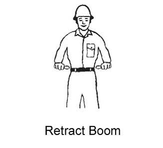
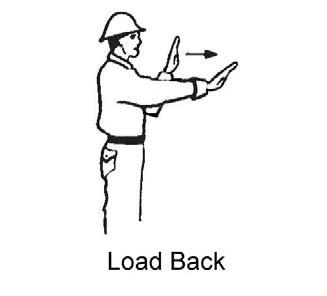
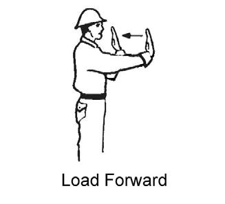
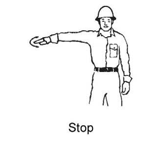
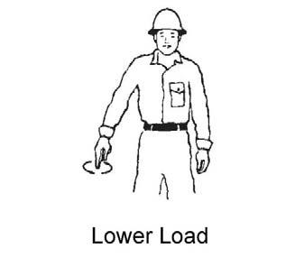
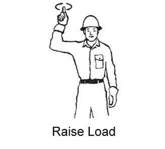
Know and understand the traffic flow patterns of your jobsite. Know all Telescopic Handler hand signals for safety. Utilize signal persons and be sure you can see the signal person and acknowledge the signals given.


When ramps must be used in transporting loads with the machine, the following are the minimum widths for safe travel:
Compacted dirt, gravel, etc.12 ft. (3.6 m) Woodboard, concrete, etc.10 ft. (3.0 m)
Permanent aisles, roadways and passageways, floors and ramps must be clearly defined or marked. Permanent or temporary protrusion of loads, equipment, material and construction facilities into the usual operating area must be guarded, clearly and distinctively marked, or clearly visible.
Maintain a safe distance from the edge of ramps, platforms and other similar working surfaces.
Controlled lighting of adequate intensity should be provided in operating areas. Where operating conditions dictate, the operator/user is responsible for having the machine equipped with lights.
Provisions must be made to prevent trucks, semi-trailers and railroad cars from being moved during loading and unloading. Wheel stops, parking brakes, or other positive holding means must be used to prevent movement during loading and unloading.
DO NOT move railroad cars and trailers with the Telescopic Handler.
DO NOT use the boom and attachment for leverage to push the machine out of mud.
IMPORTANT: DO NOT lower boom at high engine speed when attachment tool is at maximum rearward tilt. Damage to slave cylinders may result.
General Load Handling
NEVER operate controls except from the operator’s seat. NEVER jerk or use fast movements. Avoid sudden stops, starts and changes in direction.
Operation of the hydraulic system depends on engine speed and the distance the controls are moved. When operating these controls it is important to develop a technique called “feathering.” Feathering the control means starting the desired motion by moving the control a small distance away from neutral. Then after movement has started, the control can be eased to full travel. Use the same feathering technique to slow and stop the motion.
Warning
Excessive speed can be hazardous. ALWAYS exercise caution and good judgement while operating the machine.
ALWAYS maintain a safe distance from electric power lines and avoid contact with any electrically charged conductor and gas line. It is not necessary to make direct contact with a power line for power to ground through the structure of the machine. Keep the boom and load at least 10 ft. (3 m) from all power lines. Accidental contact with a power line or rupture of a gas line can result in electrocution or an explosion. Contact the “Call Before You Dig” referral system number at 8-1-1 in the U.S., or 888-258-0808 in the U.S. and Canada, to locate any underground utility lines BEFORE starting to dig.
Keep all body parts inside the operator’s station while operating the machine. BE SURE of clearance for the attachment tool when turning, working around buildings, etc.
Turning corners too fast can tip the machine, or cause a load to slide off the attachment. Sudden slowing or stopping of the machine may cause the load to drop off the attachment tool.
Be certain you can control both speed and direction before moving. Always place the machine in neutral and set the parking brake before raising or extending the boom. NEVER drive the machine up to someone standing in front of the load.
NEVER leave the operator’s station without first lowering the attachment tool to the ground. Then set the parking brake, place controls in neutral, shut off engine and remove the key. AVOID parking the machine on a slope, but if necessary, park across the slope and block the tires.
Load Capacity and Reach
This machine has flip-charts in the operator’s station that provide, at a glance, the load capacity limits at various positions of attachment tool extension and elevation. A set of the load zone charts is reproduced at the end of this manual for reference.
A typical load zone chart is shown on this page. The scale on the left indicates height in feet above the ground level. The scale on the bottom shows the distance in feet out from the front of the machine. The arc lines noted by the numbers “1” through “5” correspond with the boom extension marks on the operator side of the intermediate boom section.
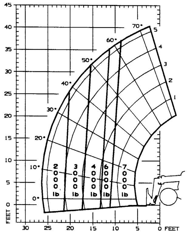
The following example illustrates proper use of the load zone charts for the Telescopic Handler:
Warning
NEVER exceed the rated operating capacity of the Telescopic Handler as shown on the load zone charts.
HANDLING NON-SUSPENDED LOADS
Picking Up the Load
Inspect the load. If it appears unstable, DO NOT attempt to move it. DO NOT attempt lifting doubletiered loads, or straddling side-by-side pallets with one on each fork. NEVER add extra unauthorized counterweights to this machine. Consider the additional weight of any attachment tool as part of the picking load capacity of the machine.
Warning
Operating conditions can reduce the machine’s safe operating capacity. Exceeding the capacity when raising or extending the boom will cause the machine to tip forward.
Approach the load slowly and squarely with the machine straight and level. Adjust the space between forks, if necessary. Engage the load equally on both forks until the load touches the carriage backrest. Tilt the forks back to position the load for travel.
Carrying the Load
Example: The operator, using a standard carriage attachment tool without outriggers, wants to raise a 4000 lb. load 25 feet high, and can only get to within 15 feet of the load placement point. Can this be done within the capacity of the machine?
Analysis: See “Typical Load Zone Chart” above. Projecting up from the 15-foot reach mark on the horizontal axis to intersect a line through the 25-foot height mark on the vertical axis shows that a load up to 4000 lb. can be placed in that zone.
During placement, the operator should observe when the boom extension mark number “4” on the boom is visible and stop further extension. The operator knows the maximum safe extension distance with the 4000 lb. load has been reached.
If the load obstructs your view, get someone to direct you. Maintain ground speeds consistent with ground conditions and that permit stopping in a safe manner.
Warning
NEVER travel with the boom above the carry position (attachment tool should be at minimum ground clearance). Boom should be fully retracted.
Use lower gear when traveling down an incline. NEVER coast with the transmission in neutral. Travel up and down grades slowly.
DO NOT operate the machine on a slope or grade that exceeds 22% or 12o.
Load Elevation and Placement
For ground level load placement, be sure the area under the load and around the machine is clear of equipment and personnel. Lower the load to the ground, tilt the forks to the horizontal position, and then carefully back away to disengage the forks from the load.
For elevated or overhead placement, bring the machine as close as possible to the landing point, and then:
1.Level the machine BEFORE raising the load. Use extreme caution for high placement. Be sure personnel are clear of the area where the load or the machine could fall or tip.
2.Set the parking brake, shift the transmission into neutral, hold the service brake pedal fully applied and slowly raise the load, maintaining a slight rearward tilt to cradle the load.
3.As the load approaches the desired height, feather the boom control at minimum speed until the load is slightly higher than the landing point.
4.Continuing the feathering technique, lower the load into place.
5.Free the forks from the load by alternately retracting and raising the boom. If this process is not possible, very slowly and carefully reverse the telescopic handler to free the forks from the load.
6.Lower the forks to travel height.
Handling Suspended Loads
Determine the weight and load center of the load to be handled. Refer to the telehandlerload chart to determine if the load can safely be handled.
Warning
NEVER exceed the rated operating capacity of the telehandler as shown on the load zone charts.
Warning
Operating conditions can reduce the telehandler’s safe operating capacity. Exceeding the capacity when raising or extending the boom will cause the telehandler to tip forward.
NOTE: Refer to the standard carriage load chart when using the boom mounted hook.
Picking Up Suspended Load
1.Rigging should be in good condition and rated for the load being lifted.
2.Rigging should comply with OSHA regulation §1910.184, “Slings,” or §1926.251, “Rigging equipment for material handling.”
3.Be sure the rigging equipment is clear of any part of the machine or machine attachment before lifting the load.
4.Avoid lifting double-tiered or any unstable loads.
5.Only lift loads vertically and clear from any adjacent obstacles. Never drag the load horizontally.
6.Use multiple lift points and taglines to restrain the load from swinging or rotating.
Carrying Suspended Load
1.Rigging between the load and attachment should be as short as possible to reduce boom height.
2.Do not raise the load more than 12 inches (305 mm) above the ground or raise the boom more than 45 degrees.
3.All telehandler movements should be performed slowly and cautiously to prevent load swing. Avoid abrupt movement. Do not exceed walking speed.
4.Use a signal person anytime the load restricts the operators view or assistance is required. The signal person should remain in contact (verbally or visually) with the operator at all times until the load is placed.
Ground Level Suspended Load Placement
1.Be sure the area under the load and around the telehandler is clear of equipment and personnel.
2.Lower the load to the ground till load is stationary and the rigging is loose from the load. Have signal person disconnect the rigging from the load.
3.Raise boom enough to clear the rigging from the load before backing the telehandler away from the load.
Elevated Suspended Load Placement
1.Bring the telehandler as close as possible to the landing point.
2.Level the telehandler BEFORE raising the load. Use extreme caution for high placement. Be sure personnel are clear of the load landing area.
3.Set the parking brake, shift the transmission into neutral,hold the service brake pedal fully applied and slowly raise the load.
4.As the load approaches the landing point, feather the boom control at minimum speed until the load is just above the landing point.
5.With the assistance of a signal person, continue the feathering technique to lower the load into place.
Warning
NEVER place the signal person between the load and the telehandler or other stationary objects.
6.Once the load is stationary on the landing point and the rigging is loose from the load, have the signal person disconnect the rigging from the load.
7.Raise boom enough to clear the rigging from the load. Slowly and carefully, reverse the telehandler till the rigging is clear of the load.
8.Lower the boom to travel height.
Installation of a Personnel Work Platform (PWP)
Warning
The machine must not be used to lift or carry personnel, or be fitted with any form of personnel work platform unless fitted with the optional PWP System.
If fitted with the PWP System, the Mandatory Work Platform Safety Rules (p. 19) must be adhered to at all times while lifting personnel.
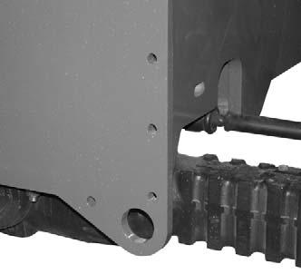
1.Center the forks on the carriage, spaced apart to match the distance required to engage the PWP.
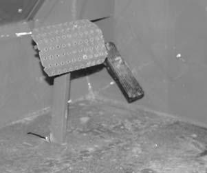
2.After the forks are fully engaged in the PWP, secure the PWP to the forks. This can be accomplished by means of a retaining pin behind the heel of the forks, as shown.
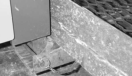
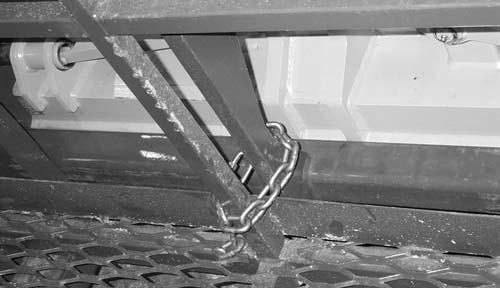
3.Secure the forks from pivoting upward in case the PWP is lowered onto an obstruction. This can be accomplished by using the chain supplied with the PWP, to secure the lower portion of the PWP to the bottom of the carriage, as shown below.
Warning
The PWP must meet ANSI/ITSDF B56.6-2005, Section 8.24. (See page 21 in the Safety chapter for PWP design requirements.) If the PWP being used does not offer means to secure the PWP to the forks and to secure the forks from pivoting, as shown in steps 2 and 3, then an alternate method must be used.
Elevating Personnel
This Telescopic Handler is primarily intended for use as a material handler. It should only be used to elevate personnel if it is equipped with the (optional) PWP System when there is no other practical option. If this machine is to be used to elevate personnel, then use only an approved work platform, lift personnel only with the PWP System activated, and follow the “Mandatory Work Platform Safety Rules” (p. 19, Safety chapter).
If this Telescopic Handler is equipped with a PWP System and is to be used for elevating personnel, the system must be activated, by the "PWP System" mode switch, which is located in the instrument and switch panel. To activate the system, apply and hold the service brakes on for three or more seconds, and press the top of the PWP rocker switch. The system is activated when the lamp in the PWP rocker switch is on continously.
NOTE: If the light is flashing, apply the service brakes until the light stops flashing.
Warning
ALWAYS check the PWP System for proper operation prior to use. (See page 83 for PWP System checking procedure.)
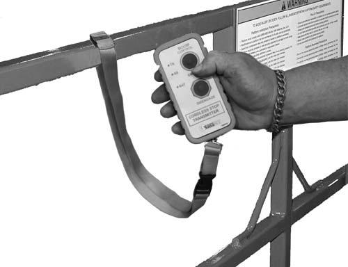
When the PWP System is active: l transmission is de-clutched into Neutral l parking brake is applied l rear axle stabilizer cylinder is locked l auxiliary hydraulic and carriage tilt and swing functions are disabled l machine inclination sensor is activated, with the result that the Telescopic Handler must be level laterally (side-to-side) and longitudinally (front-to-back) to within the factory preset limits before the boom control joystick will function l For 42-foot and 44-foot models, the remote shutdown switch is activated, with the result that the switch must be connected and in the “on” position for the boom control joystick to function. Depressing the switch will disengage the boom control joystick, and stop all platform movement. The remote shutdown switch box is supplied with a coiled electrical cable that must be connected to the outlet on the front of the innermost boom section near the carriage. The switch must be accessible by the platform personnel any time the platform is to be moved. l For 50-foot or 55-foot models, remote shutdown switch is activated, meaning that the switch must be “on” for the boom control joystick to function. Pressing the red button will disengage the boom control joystick and stop all platform movement. The remote shutdown switch box is a wireless remote control, so there is no direct connection to the Telescopic Handler. The switch must be accessible to the platform personnel at all times when the platform is to be moved.
To de-activate the system, apply and hold the service brakes on for three or more seconds, and press the bottom of the PWP System rocker switch. The system is de-activated when the lamp in the PWP System rocker switch is off.
NOTE: If the lamp in the PWP system rocker switch is flashing, apply the service brakes until the lamp goes off.
Warning
In an emergency, if the platform worker has activated the remote shut-off switch and then is not able to re-activate the switch, such as if the worker fainted, then the Telescopic Handler operator is permitted to turn off the PWP System to regain control of the boom functions, in order to lower the work platform and come to the aid of the worker. But, understand this is only permitted in case of an emergency. Otherwise, the PWP System must be used at all times when there are workers on the platform. This is the only exception!
Stabilizer System
This is an additional safety function while elevating loads for placement. At a pre-determined angle, the stabilizer cylinder on the rear axle will lock up. When this happens, the parking brake is activated. The machine will not be able to move until the boom is lowered below the pre-determined angle.
Warning
The machine becomes less stable as the load is raised higher.
NEVER use frame leveling to position an elevated load. Always lower the load to the ground and reposition the machine.
If a hydraulic boom circuit hose should break with the boom up, shut down the machine. DO NOT attempt to bring down the boom or make repairs. Call your Gehl dealer immediately.
As lift height increases, depth perception decreases. High elevation placement may require a signal person to guide the operator.
DO NOT ram the lift cylinders to the end of the stroke. The resulting jolt could spill the load.
A jib or truss boom should ONLY be used to lift and place loads when the machine is stationary and the frame is level. Transporting suspended loads must ALWAYS be done slowly and cautiously, with the boom and load as low as possible. Use taglines to restrict loads from swinging, to avoid overturn.
Road Travel
For short distance highway travel, attach a SlowMoving Vehicle (SMV) emblem (purchased locally) to the rear of the Telescopic Handler. For highway operation, obtain and install an amber flashing beacon.
NOTE: ALWAYS follow ALL state and local regulations regarding the operation of equipment on or across public highways. Whenever there is an appreciable distance between jobsites, or if driving on public highway is prohibited, transport the machine using a vehicle of appropriate size and capacity.
Transporting Between Jobsites
ALWAYS abide by the following recommended procedures and guidelines when using ramps to load the machine onto (and unload it from) a truck or trailer. Failure to heed can result in damage to equipment and serious personal injury or death!
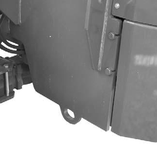
Tie-down eyes are provided for inserting chains through to secure the machine during transport.
Loading Machine Using Ramps
NOTE: A matched pair of ramps is required.
1.The ramps MUST be of sufficient strength to support the machine. The use of strong steel ramps is recommended, as well as center supporting blocks.
Warning
NEVER transport the machine with the boom raised or extended. BE SURE to secure the machine (including boom) to the truck or trailer bed using chain and binders or steel cables, to prevent any movement while transporting.
Unloading Machine Using Ramps
NOTE: A matched pair of ramps is required.
Repeat steps 1 through 5 and proceed as follows to unload the machine:
6.Remove the tie-down chains/cables.
7.If necessary, adjust the machine so that the wheels are in line and centered with the ramps.
Ramp Placement
2.The ramps MUST be firmly attached to the truck or trailer bed with NO step between the bed and the ramps.
3.The incline of the ramps MUST be less than 15 degrees. For a four-foot high truck bed, ramp length must be at least 16 feet (4.9 m) long.
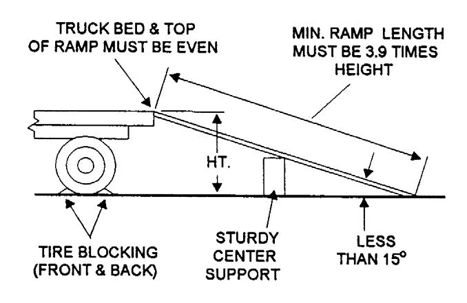
4.Ramp width MUST be at least 1-1/2 times the tire width.
5.Block the front and rear of the tires on the truck or trailer. Engage the parking brake.
6.Position the machine with the boom facing toward the front of the truck or trailer so that it is straight in line with the ramps.
7.Slowly (at the lowest engine speed possible) and carefully drive the machine up the ramps.
8.Secure the machine to the bed of the truck or trailer with tie-down chains/cables.
Warning
NEVER adjust travel direction (even slightly) while on the ramps. Instead, back off the ramps, and then realign the machine with the ramps.
8.Slowly (at the lowest engine speed possible) and carefully drive the machine down the ramps.
Theft Deterrents
Gehl Company has recorded all component part numbers and serial numbers. Users should take as many of the following actions as possible to discourage theft, to aid in the recovery of the machine in the event it is stolen, and to reduce vandalism:
1.Remove keys from unattended machines.
2.Attach, secure, and lock all anti-vandalism and anti-theft devices on the machine.
3.Lock doors of cabs when not in use.
4.Inspect the gates and fences of the equipment storage yard. If possible, keep machines in welllighted areas. Ask the local law enforcement agency to make frequent checks around the storage and work sites, especially at night, during weekends, and on holidays.
5.Report any theft to your dealer and insurance company. Provide the model and all serial numbers. Request your dealer to forward this information to Gehl Company.
General Information
Chapter 7 LUBRICATION WARNING
NEVER lubricate or service this unit when any part of the machine is in motion. ALWAYS exercise the MANDATORY SAFETY SHUTDOWN PROCEDURE (p, 13, SAFETY chapter) before lubricating or servicing this equipment.
NOTE: The Maintenance chapter (Chapter 10) in this manual has provisions for recording the dates and hourmeter readings after lubrication or other service has been performed; use those spaces to keep a log for maintaining a current service interval record. Proper routine lubrication is an important factor in preventing excessive part wear and early failure.
Lubricants
The chart on this page lists the locations, temperature ranges and recommended types of lubricants to be used when servicing this machine. Also refer to the separate engine manual for additional information regarding recommended engine lubricants, quantities required and grades.
NOTE: Refer to “Operator Services” in the Service and Storage chapter of this manual for detailed information regarding periodic checking and replenishing of lubricants.
All Grease Fittings
Use No. 2 lithium-based grease
Brake System
Uses hydraulic system oil.
Transmission Oil
Use Multi-ATF Dexron® III or equivalent
Capacity: All Models 13.75 qts. (12.9 L)
Hydraulic System Reservoir
Use Mobil DTE 15M, or an equivalent that contains anti-rust, anti-foam and anti-oxidation additives and conforms to ISO VG46/VG32.
Reservoir Capacity: 30 gallons (113.5 L)
Engine Crankcase Oil
Ambient TemperatureGrade*
-40°F - 32°F(-40°C - 0°C)SAE 0W-30 5°F - 131°F(-15°C - 55°C)SAE 5W-40
*API Service Classification: CJ-4
*API Service Classification for first 100 hours on new or rebuilt Cummins engines: CJ-4 Capacity: 15.5 quarts (14.7 L)
Diesel Fuel
IMPORTANT: Use ONLY ultra low sulfer diesel (ULSD) fuel with a maximum of 15 PPM sulfur content specified to EN590 or ASTM D975. Fuel Tank Capacity: 47 gls. (178 L)
Diesel Exhaust Fluid (DEF)
Must meet ISO 22241-1 or DIN 70070 standards. DEF Tank Capacity: 5 gls. (19 L)
Engine Coolant
IMPORTANT: Use a ethylene glycol based Extended Life Coolant and quality water mixture suitable for heavy duty diesel engines. Coolant should be a phosphate-free, silicate-free, nitrite-free and borate-free formula with corrosion inhibitors to provide wet sleeve liner cavitation and corrosion protection of all cooling system metals. Must meet or exceed ASTM D-3306 or ASTM D-6210
Factory filled with (recommended): FINAL CHARGE 50/50 PRE-DILUTED Global Extended Life Coolant/Antifreeze.
Axle Gear Oil
MobilFluid® 424 (recommended)
CHS Cenex Qwiklift HTB or equivalent
Capacity - RS9-50, RS10-44, RS10-55 and RS12-42
Front Differential: 14.8 qts. (14.0 L)
Front Planetary: 1.85 qts. each (1.75 L)
Rear Differential: 14.25 qts. (13.5 L)
Rear Planetary: 1.90 qts. each (1.80 L)
Capacity - RS6-42, RS8-42 and RS8-44
Front and Rear Differential: 15.8 qts. (15.0 L)
Front and Rear Planetary: 2.6 qts. each (2.5 L)
Filter Reference Chart Typepart Number
Engine Oil50220837
Engine FuelPrimary 50220838
Water Seperator 50220869
Air FilterPrimary 50220831
Secondary 50220832
DEF Module Filter50220851
Hydraulic ReturnL97489
Hydraulic StrainerL49327
Transmission OilL99184
Cab Ventilation211146
Greasing
Refer to the illustrations and listings for fitting locations. Wipe dirt from the fittings before greasing them to prevent contamination. Replace any missing or damaged fittings. To minimize dirt build-up, avoid excessive greasing.
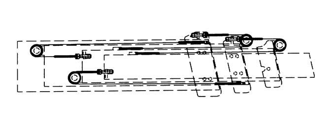
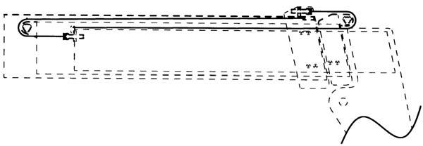
Basic Machine Grease Fitting Locations
Every 50 Hours (or weekly)
Refer to the illustrations on the facing page for locations.
--- BOOM AREA ---
1.Boom-to-frame upright pivot pins (2)
2.Rod end slave cylinder pivot pins (2)
3.Rod end lift cylinder pins (2)
4.Extend cylinder pin
5.Chain sheaves pins, (2)
6.Dynattach-to-boom nose pivot pin
7.Tilt cylinder pivot pins (2)
8.Boom slide pads - as required, front and rear
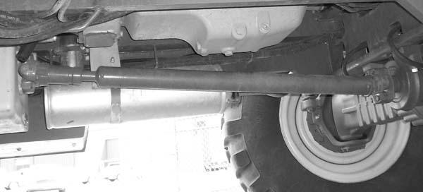
--- CHASSIS AREA ---
9.Brake pedal linkage
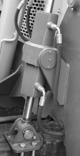
10.Wheel spindle pins (4 per axle)
11.Stabilizer cylinder pivot pins (3)
12.Axle pivot pins (2 per axle)
13.Drive shafts (3 per drive shaft)
14.Leveling cylinder pivot pins (2)
15.Base end lift cylinder pivot pins (2)
16.Base end slave cylinder pivot pins (2)
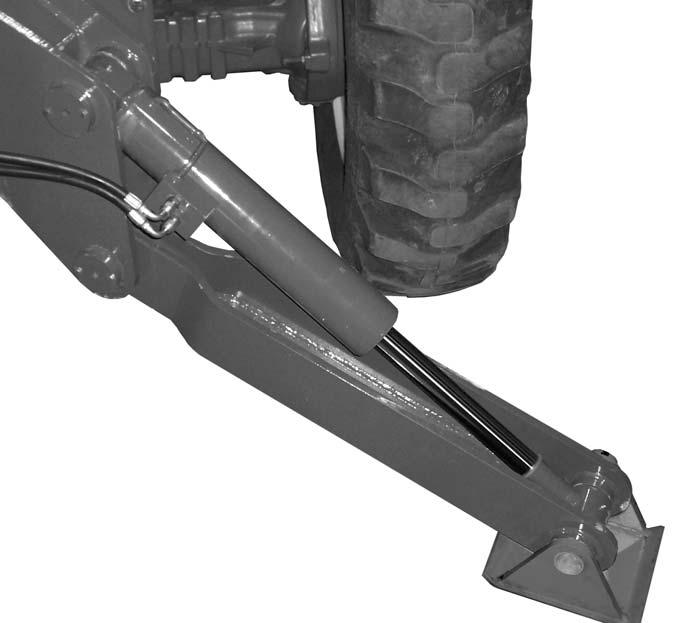
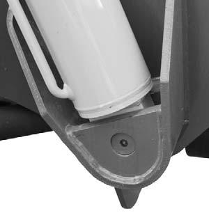
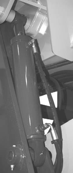
--- OUTRIGGERS ---
Refer to the illustration below.
17.Outrigger pad (2 per pad)
18.Outrigger cylinder (2 per cylinder)
19.Outrigger leg pivot (1 per leg)
General Information
Chapter 8
Service And Storage Warning
When a problem occurs, do not overlook simple causes such as an empty fuel tank. Check for leaks and broken connections. Make note of any specific symptoms, noises, etc. and contact your local Gehl dealer.
BEFORE performimg any service on the Telescopic Handler, unless expressly instructed to the contrary, exercise the MANDATORY SAFETY SHUTDOWN PROCEDURE (p. 9, Safety chapter). After service has been performed, BE SURE to restore all guards, shields and covers to their original positions BEFORE resuming machine operation.
NOTE: All service routines, with the exception of those described under the “Dealer Services” topic, are owner-operator responsibilities. All operator services described under the subtopics are also referred to on a decal located on the inside right side panel of the operator’s station. Refer to the Lubrication chapter of this manual for lubrication information.
NOTE: This Service and Storage chapter describes procedures to follow for making routine maintenance checks, adjustments and replacements. Most of the procedures are also referred to in the Maintenance chapter of this manual. For engine related adjustments and servicing procedures, refer to the engine manual provided.
Precautions
DO NOT perform any maintenance or repair without the owner’s prior authorization. Allow only trained personnel to service the machine.
Warranty repairs can only be done by an authorized Gehl dealer. Dealers know what portions of the machine are covered under the terms of the Gehl Warranty and what portions are covered by other vendor warranties.
IMPORTANT: Always dispose of waste lubricating oils, anti-freeze and hydraulic fluids according to local regulations or take them to a recycling center for disposal. DO NOT pour them onto the ground or into a drain.
Dealer Services
The following areas of internal components service replacement and operating adjustments should only be by (or under the direction of) an authorized Gehl Telescopic Handler dealer.
IMPORTANT: DO NOT service or repair major components, unless authorized to do so by your Gehl dealer. Any unauthorized repair will void the warranty.
Power Train Components
The engine and transmission are coupled directly to each other. All service routines related to the internal components are precise and critical to proper power train operation. The axle differential and planetary ends are also sophisticated assemblies that require special know-how and tools for servicing.
IMPORTANT: If any powertrain components are suspected of faulty operation, contact your Gehl dealer for assistance.
Hydraulic System Components
Valves, pumps, motors and cylinders are also sophisticated assemblies which require special know-how and tools for servicing. All cylinders are appropriately designed with particular strokes, diameters, checks and hose connection provisions unique to the machine application requirements. A schematic (Maintenance chapter) can be used as a guide for service reference, as required.
Warning
Tilt, lift, extend and leveling cylinders have counterbalance valves. These valves keep hydraulic fluid from entering and exiting the cylinders while they are not being activated, and they are under extremely high pressure. Before removing one of these valves, you ARE REQUIRED to call your Gehl dealer or Gehl Service Department. Failure to do so may result in serious injury or death.
Internal service on any of these components should only be performed by (or under the direction of) an authorized Gehl Telescopic Handler dealer.
Electrical Components
An electrical system schematic is provided, which includes instrumentation, electrical components and switch connections. It is located at the back of this manual and can be used as a guide for service reference, as required.
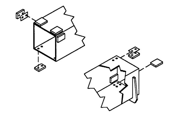
Operator Services
Some of the operator-related services will require access to components located inside the superstructure, under shields, hoods and covers. The chart on this page notes the components accessed in each particular area.
Access To Components Chart
Warning
DO NOT smoke or allow any open flames in the area while checking or servicing hydraulic, battery or fuel systems; all contain highly flammable liquids or explosive gases, which can cause an explosion or fire if ignited. Wear a face shield when disassembling spring-loaded components or working with battery acid. Wear a helmet or goggles with special lenses when welding or cutting with a torch.
When working beneath a raised machine, always use blocks, jack-stands or other rigid and stable supports. Wear appropriate protective clothing, gloves, and shoes. Keep feet, clothing, hands and hair away from moving parts.
Always wear safety glasses or goggles for eye protection from electric arcs from shorts, fluids under pressure, and flying debris or loose material when the engine is running or tools are used for grinding or pounding.
NEVER weld on bucket, forks, boom, support frame or ROPS/FOPS without the consent of the manufacturer. These components may be made with metals that require special welding techniques, or with designs that do not allow weld repairs. NEVER cut or weld on fuel lines or tanks.
If repair welding is ever required, BE SURE to attach the ground (-) cable from the welder as close as possible to the area to be repaired. Disconnect the positive (+) and negative (-) cables from the battery. Disconnect the connectors to the Electronic Control Module (ECM).
Choose a clean, level work area. Make sure you have sufficient room, clearances, and adequate ventilation. Clean the walking and working surfaces. Remove oil, grease and water to eliminate slippery areas. Utilize sand or oil absorbing compound, as necessary, while servicing the Telescopic Handler.
Before starting inspection and repair, move the machine onto a level surface, shut down engine, and release all hydraulic pressure. Always block the boom securely, or lower it to full ground contact. Place all controls in neutral.
Block the wheels. Remove the ignition key. Remove only guards or covers necessary to provide needed access. Wipe away excess grease and oil.
Excessively worn or damaged parts can fail and cause injury or death. Replace any cracked or damaged parts. Use only genuine Gehl parts for service.
Use care not to damage machined and polished surfaces. Clean or replace all damaged or painted-over plates and decals that cannot be read.
Warning
NEVER leave guards off or access doors open when the machine is unattended. Keep bystanders away if access doors are open.
After servicing, check the work performed, that no parts are left over, etc. Install all guards and covers.
Service Every 10 Hours or Daily
Warning
Static electricity can produce dangerous sparks at the fuel-filling nozzle. Do not wear polyester, or polyester-blend clothing while fueling. Before fueling, touch the metal surface of the machine away from the fuel fill to dissipate any built-up static electricity. Do not re-enter the machine but stay near the fuel filling point during refueling to minimize the build-up of static electricity. Do not use cell phones while fueling. Make sure the static line is connected from the machine to the fuel truck before fueling begins.
Ultra-Low Sulfur Diesel (ULSD) poses a greater static ignition hazard than earlier diesel formulations. Avoid death or serious injury from fire or explosion; consult with your fuel or fuel system supplier to ensure the entire fuel delivery system is in compliance with fueling standards for proper grounding and bonding practices.
CHECK FUEL and DIESEL EXHAUST FLUID LEVEL
The fuel and diesel exhaust fluid level is shown on there repective level gauge on the instrument panel. After operation each day, the fuel tank should be filled to prevent water from condensing in the tank. Diesel exhaust fluid should be added if it is low. Engine power will be reduced if the level is allowed to drop to low. See the Lubrication chapter for the diesel fuel and diesel exhaust fluid requirements.
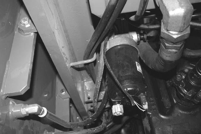
Check Fuel Water Separator
Check Engine Oil Level
With the machine on level ground, and the engine stopped for 15 minutes or more, open the access door on the right side of the engine cover and remove the engine dipstick. Wipe it clean, re-insert it and remove to obtain a reading. If the oil level is below the crosshatch pattern on the dipstick, fill with the required amount of oil to bring the level to within the crosshatch pattern. Oil levels anywhere within the crosshatch are considered full. See the Lubrication chapter for the type of oil to use.
NOTE: The engine is equipped with a water-infuel sensor at the water separator fuel filter. An error code will display in the multi-function display if water is present in the water separator fuel filter.
Drain water and sediment from the separator daily using the following procedure: a.Shut off the engine. b.Use your hand to open the drain valve. Turn the valve counterclockwise approximately 3 1/2 turns until the valve drops down 1 inch (25.4 mm). c.Drain until clear fuel is visible. e.Close valve lifting valve up to contact the filter and then turn it clockwise until it is hand tight.
IMPORTANT: Drain water into a suitable container and dispose of properly.
IMPORTANT: When closing the drain valve, do not overtighten the valve. Overtightening can damage the threads.
A drain plug is also provided in the bottom of the fuel tank for removing condensation and other foreign materials. Open the plug and allow water and fuel to drain into a container until only clear fuel is flowing from the tank.
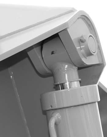
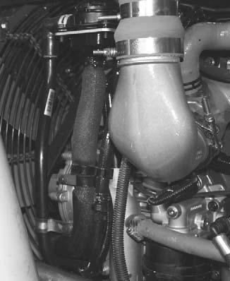
Check Radiator Coolant Level
With the machine on level ground, visually check the level of the engine coolant through the sight gauge located on the back of the radiator as shown. Coolant level should be at the center of the sight gauge.
If the coolant level is low, remove the radiator cap and slowly add a low-silicate ethylene glycol based coolant mixed with quality water and supplemental coolant additives (SCAs) suitable for heavy-duty diesel engines until the coolant is at the center of the sight glass. See your engine manual for additional information. Replace the radiator cap securely.

Warning
DO NOT remove the radiator cap when the engine is running hot or overheated. Coolant is extremely hot and under pressure and it can burn your skin. Allow sufficient time for the radiator to cool BEFORE relieving the pressure and removing the cap.
NOTE: Do not fill the radiator to the top of the radiator tank.
NOTE: If the engine is operated with a loose radiator cap, the pressure bypass will not work and the engine will run hot.
Check Transmission Oil Level
The machine must be on level ground. With the engine and transmission at operating temperature, parking brake on, transmission in neutral and engine speed at low idle, remove the access cover to the transmission and hydraulic pump. Remove the dipstick and check the oil level. Add the required amount of oil to bring the level to the FULL mark. See the Lubrication chapter for the type of oil to use.
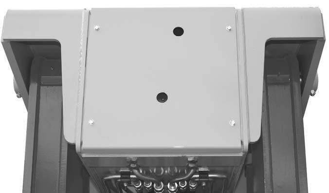
Check Hydraulic Oil Level
The machine must be on level ground with boom lowered and completely retracted. The fluid MUST be cool when checking the reservoir level, to reduce the possibility of overfilling the hydraulic system.
Visually check the level of the hydraulic oil through the sight gauge located on the right side of the front hood. If low, remove the access cover from the front hood to replenish the oil through the filler cap. See the Lubrication chapter for the type of oil to use.
IMPORTANT: Be careful when removing the reservoir filler cap so that no dirt or other foreign matter enters the hydraulic system. DO NOT OVERFILL.
Check Foam Filled Or Solid Rubber Tires
Check these tires for deep cuts, abrasions or gouges in the wear surface and sidewalls that may affect the tires performance.
NOTE: The RS9-50 model telehandler requires the use of foam filled or solid rubber tires.
Check Tire Pressures
To ensure proper operating stability and extend tire life, proper and equal tire pressure should be maintained in all four tires.
Check tire pressures “cold.” Inflate as necessary per the chart below:
13.00 x 24 - 12 PR: 65 psi (450 kPa)
14.00 x 24 - 12 PR: 62 psi (430 kPa)
14.00 x 24 - 16 PR: 70 psi (480 kPa)
NOTE: If the tires have been filled with water or calcium chloride for ballast, a calcium chloride tire pressure gauge MUST be used to check the tire pressure.
Warning
Inflating or servicing tires can be dangerous. Whenever possible, trained personnel should service and mount tires. To avoid possible death or serious injury, follow the safety precautions listed:
1.BE SURE the rim is clean and free of rust.
2.Lubricate both the tire beads and rim flanges with a soap solution. DO NOT use oil or grease.
3.DO NOT place fingers on the tire bead or rim during inflation. Use a clip-on tire chuck with a remote hose and gauge, which allows standing clear of the tire while inflating it.
4. NEVER inflate beyond 35 psi (240 kPa) to seat the beads. If the beads have NOT seated by the time the pressure reaches 35 psi (240 kPa), deflate the assembly, reposition the tire on the rim, relubricate both parts and re-inflate. Inflation pressure beyond 35 psi (240 kPa) with unseated beads may break the bead or rim with explosive force sufficient to cause death or serious injury.
5.After seating the beads, adjust the inflation pressure to the recommended operating pressure listed.
6.DO NOT weld, braze, or otherwise attempt to repair and use a damaged rim.
To ensure proper load carrying capability, original equipment tires comply with the specifications published in the Tire and Rim Association Yearbook Replacement tires MUST meet the same specifications. When replacing tires, be sure all tires are of the same type, quality and load rating, and the same size as the original equipment. When removing tires, follow industry safety practices. Deflate completely prior to removal. After assembly of the tire on the rim, use a safety cage or restraining device while inflating.
Check Wheel Nut Torque
On new machines, or any time a wheel has been removed, re-torque until 450 ft.-lbs. (610 Nm) is maintained.
Check Instruments Operation
Allow the engine to warm up for 1-2 minutes or 2-4 minutes in below freezing temperatures before beginning operation. Indicator lamps should be OFF and gauges should register normal readings. Tilt the frame from side to side with the frame leveling control and note the angle indicator movement.
Check General Machine Operation And Condition
Are any decals missing or damaged? Are all guards, shields and covers in place? Do all controls function smoothly and properly? Are there any abnormal vibrations or noises? Are any hose or fitting connections leaking? Is the engine exhaust color normal?
Check Crankcase Breather Tube
Inspect the bottom flexible end of the tube for sludge, debris, or ice in the tube.
If sludge debris or ice is found, clean the tube with detergent and warm water or solvent. Dry the tube with compressed air.
Visually inspect the tube for cracks or damage, replace if necessary.
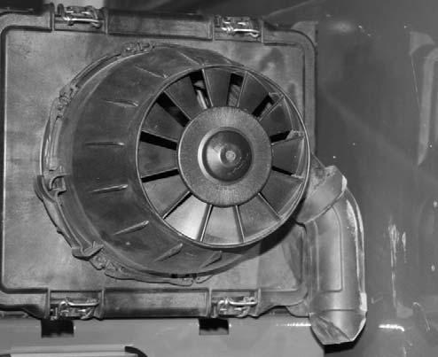
Check Dust Ejection Valve
Inspect the dust ejector for cuts and tears. Replace the valve if damage is found.
The dust ejector is a thin flexible rubber boot located at the bottom of the pre-cleaner on the air cleaner assembly. It is used to accumulate and remove dust ejected from the pre-cleaner.
Purge the dust ejection valve of dust by squeezing the valve until it opens. This may have to be performed multiple time depending on severity of dust or debris in the valve. If dust will not purge from the valve by squeezing the valve, remove the valve and clean it out by hand.
CHECK PERSONNEL WORK PLATFORM (PWP) SYSTEM (if used)
Warning
If the PWP System fails to operate properly during any of the PWP System checks, DO NOT USE the machine until the cause has been corrected. Contact your dealer (or Gehl Company) for service information and parts.
Machine Position
The following must be performed before begining the PWP System checking procedures:
1.Machine on level surface,
2.Boom fully lowered,
3.Frame level,
4.Transmission in “N” (Neutral),
5.Parking brake switch “OFF,”
6.PWP System switch “OFF,”
7.Remote switch plugged in and “ENGAGED.”
Activation Tests
To test the PWP System activation logic:
1.Start the engine and press the PWP rocker switch to “ON.” l The PWP System lamp in the switch should be flashing. l The PWP switch lamp should be illuminated continuously after three seconds, indicating that the PWP System has been activated. l The parking brake should engage, as indicated by the lamp in the parking brake switch illuminating. l The carriage tilt and auxiliary functions should now be disabled. The joystick control should continue to function normally for boom raise/lower and extend/retract.
2.Apply the service brakes.
Lockout Tests
To test the transmission and joystick control lockout logic: l The transmission should remain de-clutched, allowing the engine to increase speed easily. l Return the transmission selector to “N” (Neutral) after the check.
1.Shift transmission into “F” (Forward) and increase the engine speed slightly.
2.Have an assistant move the remote shutdown switch to “Dis-engaged.” l The joystick control should now be disabled, so that boom raise/lower and extend/retract will no longer function. l Have the assistant move the remote shutdown switch to “Engaged” after the check. l The joystick control should now be disabled so that boom raise/lower and extend/retract no longer function. l Repeat the procedure with the frame tilted to the left. l Return the frame to a level position after the checks.
3.Tilt the frame to the right slightly more than two degrees.
De-activation Tests
To test the PWP System de-activation logic:
1.Turn the key switch to “OFF” and wait for the engine to stop. Then turn the key switch back to “ON.” l The PWP switch lamp and the parking brake switch lamp should both be illuminated.
2.Turn the key switch to “OFF” and then turn the PWP rocker switch to “OFF.” Turn the key switch back to “ON.” l The PWP switch lamp should be flashing and the parking brake switch lamp should be on continuously. l The PWP switch lamp and the parking brake switch lamp should go off after approximately three seconds of brake pedal application.
3.Start the engine and apply the service brakes.
If PWP System fails to perform properly, troubleshoot using the chart on page 83. Contact your dealer for service information and parts.
Service Every 50 Hours or Weekly
Lubricate Grease Points
Refer to the Lubrication chapter of this manual for grease fitting locations and other related details.
100 Hours (New Machine Only)
The following initial oil and filter changes should be made at 100 hours on a new machine. Thereafter these changes should be made at the regular maintenance schedule listed below. Refer to those schedules for the necessary procedures.
Engine Oil and Filter(1000 Hours)
Transmission Oil and Filter(1000 Hours)
Hydraulic Return Filter Element(1000 Hours)
Torque the boom chains after the first 100 hours of operation on new machines or anytime a chain has been replaced. Thereafter the boom chains should be inspected for wear and proper tension at the regular service interval of 250 hours. Refer to the boom chain torqueing procedure in the 250 hour service interval.
NOTE: Perform all other service requirements up to this point, as well as the following:
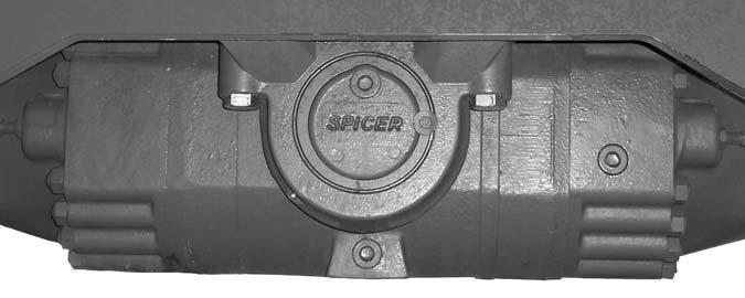
Check Axle Oil Levels
Differential
NOTE: The Telescopic Handler should be on a level surface for this procedure.
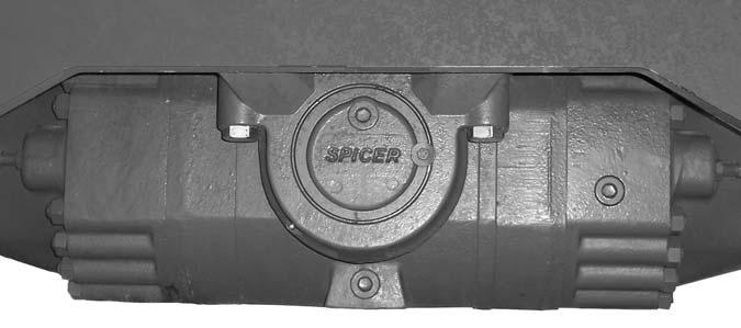
Remove the oil check plug. See illustration below. Oil should flow from the hole. If low, remove the oil fill plug and add oil until it flows from the check hole. Replace the plug, wait 10 to 15 minutes and repeat the fill procedure. Continue this process until the differential is full. See the Lubrication chapter for the proper oil specification. Replace the check and fill plugs.
Check And Torque Boom Leaf Chains
Inspect the leaf chains for proper tension. On the threesection boom, two of the chains are on the top front of the boom. A third chain is accessible from inside the rear of the boom (see three-section boom illustration on the next page).
Torque the two chains on the front of the three-section boom to 30 ft.-lbs. (40 Nm). Lubricate with 80W-90 oil.
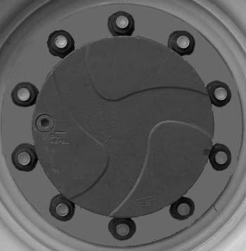
Planetary Hubs
NOTE: The planetary hubs can be checked without jacking up the machine.
The planetary hubs have one plug each used for filling and draining. See illustration below. For checking the level and filling, position the wheel until the oil level arrow is horizontal. Remove the plug. If oil does not run out, add oil until it overflows. Check the remaining hubs the same way. Refer to the oil specifications found in the Lubrication chapter of this manual.
IMPORTANT: On the three-section boom, on new machines or when chains have been replaced, it is necessary to retorque the front double chain assembly after one hundred (100) hours of operation. Failure to do so may allow the chains to become slack, which can result in a chain jumping off a sheave. If this occurs, it could result in severe damage to the boom assembly.
On the four-section boom, three chains are on the top front of the boom. A fourth and fifth chains are accessible from the rear of the boom (see four-section boom illustration).
Torque the three chains on the front of the four-section boom to 50 ft.-lbs. (68 Nm). Lubricate with 80W-90 oil.
IMPORTANT: On the four-section boom, on new machines or when chains have been replaced, it is necessary to retorque the front-center single chain and the front-outer double chains after one hundred (100) hours of operation. Failure to do so may allow the chains to become slack, which can result in a chain jumping off a sheave. If this occurs, it could result in severe damage to the boom assembly.
The retract chains on the 2nd intermediate boom and the inner boom are pre-set at the factory and do not require adjustment, unless they are replaced.
Inspect the leaf chains for wear. Run the boom out slowly to inspect. Conditions to look for include: cracked or broken plates, protruding or turned pins, and excessive wear. With a steel tape, measure 16 links of the strand that flexes over the sheaves. If the section measures 12.375” (314 mm) or more, the chain should be replaced. DO NOT repair sections of a chain. Replace the complete chain.
Chain anchors and sheaves also require inspection, for worn or broken fingers and worn flanges.
After any chain has been replaced, operate under loaded conditions and re-check the torque. Adjust the chains per the following procedure: Extend the boom to its maximum length, then retract the boom slowly until the chain slack allows the chain to rest on the top of the boom. Torque the two chains on the front of the three-section boom to 30 ft.-lbs. (40 Nm) and the three chains on the front of the four-section boom to 50 ft.lbs. (68 Nm). Lubricate with 80W-90 oil.
Check Boom Slide Pad Wear And Clearance
The boom is equipped with special nylon low-friction slide pads between the telescopic sections (see “Typical Slide Pad Detail” illustration). These are pregreased and initially worn in at the factory. Normally greasing is not required, except for maintaining a light film of grease on the pad tracking areas of the boom sections. An exception would be if a boom section has been replaced.
Visually check for loose pad bolts. The bolts are torqued to 30 ft.-lbs. (40 Nm). If the bolts are retorqued at any time, Loctite® 271 (red) thread lock or equivalent must be re-applied to the bolts.
If the boom starts to chatter under load, grease the slide pads and wipe off the excess grease. Maintain a clearance of 1/16” between the top or side slide pads and the boom. Shims can be added to achieve the proper clearance. Loosen the bolts and insert shims until proper clearance is obtained.
NOTE: When inserting shims in the side slide pads, be sure to place equal shims on both sides of the boom for even distribution of clearance.
Re-apply Loctite® 271 (red) thread lock or equivalent to the bolts and re-torque to 30 ft.-lbs. (40 Nm). Bottom slide pads should not be shimmed and should be replaced when the thickness is worn down to 3/8” (9.5 mm).
Failure to maintain proper slide pad clearance and thickness could cause damage to the boom, resulting in sudden boom failure.
CHECK CHARGE-AIR-COOLER AND PIPING
Inspect the charge-air-cooler for dirt and debris blocking the fins. Check for cracks, holes or other damage.
Inspect the charge-air-piping and hoses for leaks, holes, cracks, or loose connections. Verify the chargeair-piping hose clamps are torqued to 45 in-lbs.
Replace any damaged or worn parts.
Service Every 500 Hours or 6 Months
Check The Batteries And Cables
The batteries furnished in the machine are 12-volt, wet-cell batteries.
Warning
Explosive gas is produced while a battery is in use or being charged. Keep flames or sparks away from the battery area. Make sure battery is charged in a well-ventilated area.
NEVER lay a metal object on top of a battery as a short circuit can result.
Battery acid is harmful on contact with skin or fabrics. If acid spills, follow these first aid tips:
1.IMMEDIATELY remove any clothing on which acid spilled.
2.If acid contacted the skin, rinse the affected area with running water for 10 to 15 minutes.
3.If acid came in contact with the eyes, flood the eyes with running water for 10 to 15 minutes. See a doctor at once. NEVER use any medication or eye drops unless prescribed by the doctor.
4.To neutralize acid spilled on the floor, use one of the following mixtures: a.1 pound (0.5 kg) of baking soda in 4 quarts (4 liters) of water. b.1 pint (0.4 liters) of household ammonia in 4 quarts (4 liters) of water.
Whenever battery is removed from the unit, BE SURE to disconnect the negative (-) battery terminal connection first.
The top of the battery must always be kept clean. Clean the battery with a brush dipped in an alkaline solution (ammonia or baking soda and water). After the foaming has stopped, flush the top of the battery with clean water.
Use an inductive charging and cranking system analyzer to load-test the state of charge of the battery. If the charge is low, use a battery charger to charge the battery. Replace the battery if it will not except a charge or will not maintain a charge.
If conventional batteries are used, remove the cell caps or covers and check the electrolyte level in each cell. Fill each battery cell with water.
Use a hydrometer to measure the specific gravity of each cell. If the specific gravity of any cell is below 1.200, the battery must be replaced.
If the terminals and cable connection clamps are corroded or have a buildup, disconnect the cables and clean the terminals and clamps with a battery brush or wire brush untill the terminal and connections are shiny.
Connect the cables and tighten the battery connections. Coat the terminals with grease to prvent corrosion. Wash hands after handling the battery.
Jump Starting
If the battery becomes discharged or does not have enough power to start the engine, use jumper cables and the following procedure to jump-start the engine.
Warning
The ONLY safe method for jump-starting a discharged battery is for TWO PEOPLE to perform the following procedure. The second person is needed for removing the jumper cables so that the operator does not have to leave the operator’s compartment while the engine is running. NEVER connect the jumper cables directly to the starter solenoid of either engine. DO NOT start the engine from any position other than the operator’s seat, and then ONLY after making sure all controls are in “neutral.”
Closely follow the jump-start procedures, in the order listed, to avoid personal injury. In addition, wear safety glasses to protect your eyes, and avoid leaning over the batteries while jump-starting.
DO NOT attempt to jump-start the machine if the battery is frozen, because this may cause it to rupture or explode.
IMPORTANT: BE SURE that the jumper battery is also a 12-volt D. C. battery, and the vehicle used for jump starting has a negative-ground electrical system.
1.Turn the key switches on both vehicles to “OFF.” Be sure that both vehicles are in “Neutral” and NOT touching.
2.Connect one end of the (red) positive (+) jumper cable to the positive (+) battery terminal on the disabled machine first. DO NOT allow the positive (+) jumper cable clamps to touch any metal other than the positive (+) battery terminals. Connect the other end of the positive jumper cable to the jumper battery positive (+) terminal.
3.Connect one end of the (black) negative (-) jumper cable to the jumper battery negative (-) terminal.
4.Make the final negative (-) jumper cable connection to the disabled machine’s engine block or frame (ground) NOT to the disabled machines negative battery post. If making the connection to the engine, keep the jumper cable clamp away from the battery, fuel lines, and moving parts.
NOTE: Twist the jumper cable clamps on the battery terminals to ensure a good electrical connection.
5.Start the engine. If it does not start immediately, start the jumper vehicles engine to avoid excessive drain on the booster battery.
6.After the machine has started and is running smoothly, have the second person remove the jumper cables (negative (-) jumper cable first) from the jumper vehicle battery, and then from the disabled machine, while ensuring NOT to short the two cables together.
Allow sufficient time for the alternator to build up a charge in the battery before operating the machine or shutting off the engine.
NOTE: If the battery frequently becomes discharged, have the battery checked for possible dead cell(s), or troubleshoot the electrical system for possible short circuits or damaged wire insulation.
Check Fan Belt Tensioner
With the engine stopped, check the tensioner arm, pulley and stops for cracks. If any cracks are noticed, the tensioner must be replaced.
With the belt installed, verify that neither tensioner arm stop is in contact with the spring casing stop. If either of the stops is touching:
Verify that the correct belt is installed.
If the correct belt is installed, replace the belt.
After replacing the belt, if the tensioner arm stops are still in contact with the casing stop, replace the tensioner.
With the belt installed, check the location of the belt on the belt tensioner pulley. The belt should be centered on, or close to the middle of the pulley. Misaligned belts, either to far forward or backward, can cause belt wear, belt roll-off malfunctions, or increase uneven tensioner bushing wear. If belt is not centered on the tensioner pulley, the tensioner will likely need to be replaced.
Refer to the engine Operation and Maintenace Manual for additional information.
Check Coolant System Antifreeze
Check the antifreeze concentration. Use a mixture of 50 percent water and 50 percent ethylene glycol or propylene glycol-base antifreeze to protect the engine to -25° F (-32° C) year round.
An antifreeze refractometer provides a reliable, easy to read, and accurate measurement of freezing point protection and antifreeze concentration.
To check the antifreeze concentration:
1.Place a drop of coolant on the refractometer window and shut the lid.
2.Look through the eyepiece and focus.
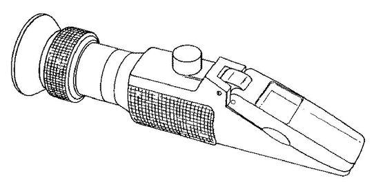
3.Record the freeze point protection for either ethylene glycol or propylene glycol coolants.
NOTE: Factory filled with an ethylene glycol based antifreeze.
Antifreeze is essential in every climate. It broadens the operating temperature by lowering the coolant freezing point and raising its boiling point. The corrosion inhibitors also protect the cooling system components from corrosion and provide longer componet life.
Clean Air Conditioning Condenser
NOTE: Clean the condenser more often if there is a noticeable decrease in A/C performance.
IMPORTANT: Do not use a water jet or high-pressure steam, because this could damage the fins.
1.Remove the six screws (1) from the top cover of the condenser.
CLEAN/CHANGE CAB VENTILATION FILTER
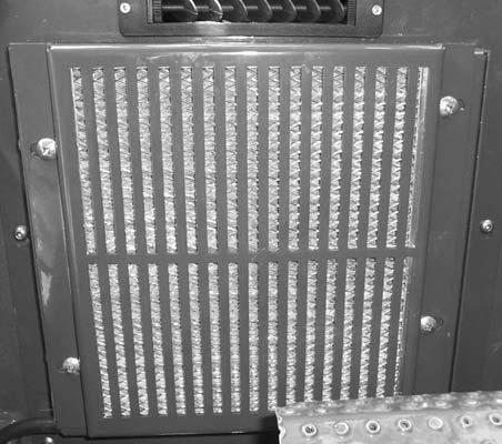
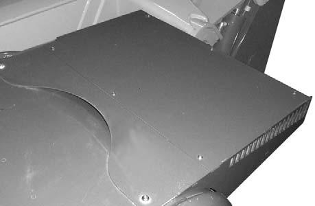
NOTE: Clean or change the filter more often if there is a noticeable decrease in air flow from the air vents.

1.Remove the four screws (1) from the filter protective cover located on the lower portion of the dash in front of the brake pedal.
2. Remove the cover to gain access to the condenser (2).
3.Clean any large debris that may have collect on the top side of the condenser.
4.Clean the condenser use a jet of compressed air aimed in the same direction as the air flow.
NOTE: To aid in the cleaning process, carry out this operation with the condenser fans running.
5.Re-install the top cover.
2. Remove the filter from the cover.
3.Clean the filter with a jet of compressed air.
4.Check the condition of the filter and replace it if neccessary.
5.Install the filter in the protective cover, then reinstall the protective cover.
NOTE: Perform all other service requirements up to this point, as well as the following:
Change Fuel Filter
The frequency of filter replacement will be determined by the cleanliness of available fuel, the care used in storing fuel supplies and the operating conditions in which the machine is used.
IMPORTANT: Catch and dispose of any spilled fuel according to local waste disposal regulations.
Warning
NEVER service the fuel system while smoking, while near an open flame, or after the engine has been operated and is hot.
1.Thoroughly clean fuel filter assembly and surrounding areas.
2.Use a 32 mm hex drive on the bottom of the filter canister to remove it.
6.Install the new o-ring seal on the filter canister. Lubricate the o-ring seal with clean lubricating oil.
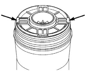
3.Remove and discard the filter element from the canister. Remove and discard the oring on the filter canister.
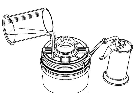
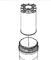
6.Remove the block-off plug from the center of the filter installed in Step 5. Install the filter on the filter head until it contacts the filter head. Then using a 32 mm hex drive tighten the canister to 24 ft-lb (32 Nm).
IMPORTANT: Do not overtighten the canister as it could damage the filter element seal and threads.
7.The fuel system must be primed after changing the fuel filter or if the fuel tank runs out of fuel.
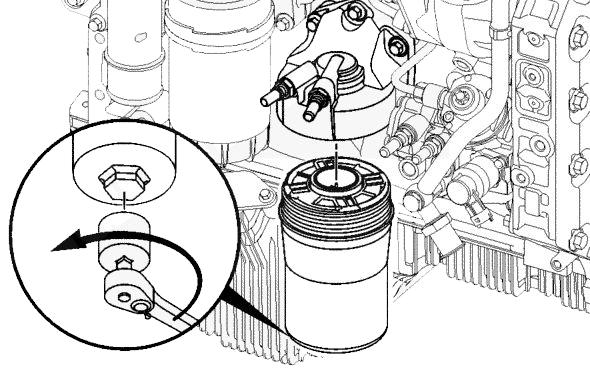
Fuel Priming Procedure
When the fuel filter is removed and replaced, or if the engine runs out of fuel, the fuel system must be primed. Refer to the following procedure for the proper fuel priming procedure.
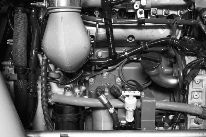
4.Install a new filter element making sure the tabs of the filter element are seated in the canister.
5.Use the clean side block-off plug packed with the filter to block the center of the filter before prefilling the filter with fuel. Pre-fill the filter making sure to pour fuel only in the outside portion of the filter as shown. Do not to pour fuel into the center of the filter as this will cause unfiltered fuel to enter the system.
2.Unlock the priming pump be turning the knob counterclockwise about 1 turn. Pump the primer by pulling the knob out approximately 3/4 inch and pushing it back in until resistance is felt. Priming could take 140 to 150 strokes for a dry filter or 20 to 60 strokes if the new filter was pre-filled.
3.Push the priming knob back in completely and turn it clockwise about 1 turn to lock it.
4.Crank the engine. If the engine does not start after 30 seconds, turn the key to the OFF position.
5.Repeat priming procedure 2 - 4 unti the engine starts.
When the engine starts, it may run erratically with increased noise levels for a few minutes until air is purged from the fuel system.
NOTE: It is possible that Fault Code 157-18 can become active after fuel filter replacement, due to the air in the system. Run the engine until the air is purged from the system then clear the fault code.
Warning
Escaping diesel fuel under pressure can have sufficient force to penetrate the skin. Before applying pressure to the fuel system, BE SURE all connections are tight and lines and hoses are not damaged. Use a piece of wood or cardboard to search for suspected leaks. If injured by escaping fuel, see a doctor familiar with this type of injury at once or gangrene may result.
Change Water Separator Element
IMPORTANT: Catch and dispose of any drained or spilled fuel according to local waste disposal regulations.
1.Disconnect the water sensor wire from the bottom of the element.
2.To prevent excess fuel spillage, use a clamp or similar tool to pinch the rubber fuel line leading to the water separator from the fuel tank.
3.Drain the fuel from the separator element.
4.Using a 1 inch socket or wrench on the bottom of the separator element, turn the element counterclockwise to remove it from the head.
5.Pre-fill the separator element making sure to pour fuel only in the outside portion of the filter.
6.Install the separator element on the head until it contacts the filter head. Then using a 1 inch wrench tighten the element to 204 in-lb (24 Nm).
IMPORTANT: Do not overtighten the element as it could damage the element seal and threads.
7.Remove the clamp from the fuel line and prime the fuel system following the fuel priming procedure.
Diesel Fuel System
Whenever faulty or plugged injectors or injection pump service is indicated by abnormal engine operation, see your authorized engine dealer.
NOTE: Only an authorized engine dealer can perform warranty service on the engine.
Change Engine Oil And Filter
Change the engine oil and filter using the following procedure:
1.Operate the engine until the water temperature reaches 140° F (60° C).
2.Shut off the engine and remove the oil drain plug. IMPORTANT: DO NOT discharge oil onto ground. Catch and dispose of per local waste disposal regulations.
2.The engine oil filter should be changed at every oil change interval. Using a 1/2” drive wrench on the bottom of the filter, remove and discard the filter.
IMPORTANT: Filtration of oils is critical to proper lubrication. Always change the filter with every oil change.
3.Be sure the old filter gasket is not stuck to the filter head. Remove it if neccessary. Clean the gasket surface of the filter head.
4.Apply a thin coat of clean engine oil to the gasket surface of the new oil filter. Fill the new filter with clean engine oil.
5.Install the oil filter by hand until firmly against the filter head. Tighten the filter an extra 3/4 to 1 turn after gasket contacts the filter head.
6.Clean and check the oil drain plug threads and sealing surface. Re-install the drain plug. Torque to 212 in-lb (24 Nm).
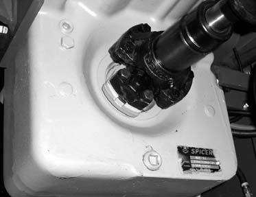
7.Re-fill the crankcase with new oil. Follow specifications in the Lubrication chapter for type and viscosity of new oil.
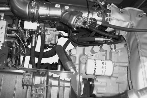
8.After new oil has been added, run the engine at idle speed until the oil pressure lamp is off. Check for leaks at the filter and drain plug.
9.Shut off the engine. Wait approximately 5 minutes to let the oil drain back to the oil pan. Check the oil level. Add oil as necessary to bring oil level to the high mark on the dipstick.
Change Transmission Oil And Filter
Operate the machine long enough to warm the transmission oil to 150°F-200°F (65°C-93°C). Shut off the engine. Access to filter is from under the access cover on the front hood section. Access to the drain plug is from underneath the machine. Proceed as follows:
1.Remove the drain plug and drain old oil. Replace the drain plug.
2.Remove and discard the oil filter. Wipe the sealing surface on the transmission with a clean cloth. Apply a thin coat of clean oil to the new oil filter gasket. Hand tighten.
Transmission
Dipstick and Filler
Transmission Filter
3.Refill the transmission with new oil as listed in the Lubrication chapter of this manual.
IMPORTANT: DO NOT OVERFILL! lf the oil level is too high, oil foaming, excessively high oil temperature and oil leakage at the seals could result.
4.Start and run the machine long enough for the oil to circulate and warm slightly. Recheck the level with the dipstick.
Change Hydraulic Return Filter Element
Warning
When servicing the hydraulic system, lower the boom to the ground.
This element is a cartridge-type accessible from a housing on top of the hydraulic reservoir. Initial replacement is after the first 100 hours. See illustration. Remove the top cover of the housing. Remove the element and discard. Insert the new element into the housing and replace the cover.
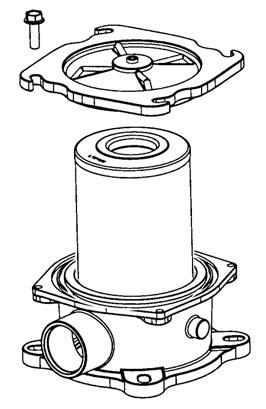
Housing Top
Transmission Drain Plug
IMPORTANT: DO NOT discharge oil onto ground. Catch and dispose of per local waste disposal regulations.
Filter Element
Filter Housing
Reservoir Filter Removal
CHANGE AIR FILTER ELEMENT(S)
The air cleaner assembly consists of an primary filter element and a secondary filter element. Air filter restriction is indicated by the check engine lamp and an error code in the multi-functional display.
3.Clean out any dirt build up in the housing. Leave the secondary element installed during this step to prevent debris from entering the engine intake manifold.
4.Place a new primary element in the housingso the seal is toward the secondary element. Push it in the housing so all surfaces are seated inside the housing.
NOTE: Cleaning the primary element is not recommend.
5.Re-install the end cap assembly and latch the four latches.
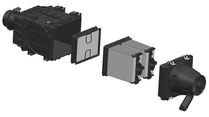
Secondary Element
NOTE: Replace the secondary element ever other time the primary element is replaced or if it is visibly dirty.
The amber check engine lamp will flash for 30 seconds when the ignition switch is turned ON, and an error code will be displayed to indicate the air filter should be replaced.
If the air filter is not replaced and the restriction becomes more severe, the amber check engine lamp will light and stay ON, and an additional error code will display resulting in possible engine power reduction.
The outer element should be replaced whenever indicated by the multi-functional display. The inner element should be replaced every other time the outer element is replaced, unless the outer element is damaged or the inner element is visibly dirty. Along with a daily check of the restriction indicator, check that the air cleaner intake hose and clamps, and the mounting bracket hardware are properly secure.
Unlatch the four latches on the air cleaner and remove the end cap assembly. Clean out any dirt built up in the end cap assembly.
Primary Element Replacement
1.Unlatch the four latches on the air cleaner and remove the end cap assembly. Clean out any dirt built up in the end cap assembly.
2.The primary element has built in handles, grasp the handles and remove the element from the housing. Never remove the secondary element unless it is to be replaced.
Before removing the secondary element from the housing, clean out any dirt build up in the housing. Leave the secondary element installed during this step to prevent debris from entering the engine intake manifold. Secondary element removal:
1.Remove the primary element following Steps 1 and 3 of the primary element replacement procedure.
2.The secondary element is removed by pulling on the two plastic ring tabs on the face of the element.
3.Push the new secondary element into the back of the housing so all surfaces are seated inside the housing. Apply pressure to all four corners to make sure the element is secure within the housing.
4.Install the primary element following Steps 4 and 5 of the primary element replacement procedure.
Change Axle Differential And Planetary Oil
Differentials
1.Remove the three drain plugs and drain the used oil. Replace the drain plugs (see illustration on the next page).
IMPORTANT: DO NOT discharge oil onto ground. Catch and dispose of per local waste disposal regulations.
2.Remove the fill/check plug. Fill the differential with fresh oil as specified in the Lubrication chapter. When the oil flows from the check hole, replace the plug. Wait 10 to 15 minutes and repeat this process until the axle is full.
Repeat this procedure with the other axle.
Axle Planetary Hubs
The hubs have one plug each used for draining and filling (see illustration).
Check Exhaust System
Examine the entire exhaust system for possible holes and leaks. Re-tighten any loose clamps and make sure the manifold outlet gasket is not leaking.
Check Radiator Pressure Cap
Make sure the radiator cap is a 16 psi (1.1 bar) pressure cap. Inspect the rubber seal for damage. Replace it if damage is visible. Inspect the radiator filler neck for cracks or other damage.
An incorrect or malfunctioning radiator cap can result in the loss of coolant and the engine running hot.
Service Every 2000 Hours or Two Years
NOTE: Perform all other service requirements up to this point, as well as the following:
Check Hydraulic System Relief Pressures
Pressure settings for relief valves are pre-set at the factory. Three test ports are provided under the front hood access cover.
1.Position the wheel until the oil level arrow points down. Remove the drain/fill plug and allow the oil to drain. Replace the plug.
IMPORTANT: DO NOT discharge oil onto ground. Catch and dispose of per local waste disposal regulations.
2.Re-position the hub so the oil level arrow is horizontal. Fill with fresh oil as specified in the Lubrication chapter. When the oil runs out, install the drain/fill plug.

Repeat this procedure on the three remaining hubs.
Check Fan Belt And Fan Hub Condition
Remove the Fan belt and check fan belt for wear , cut or cracks If the belt shows wear or cuts, it should be replaced. Order a replacement belt from your Gehl dealer.
With fan belt removed, check the fan hub for wobble or excessive end clearance.
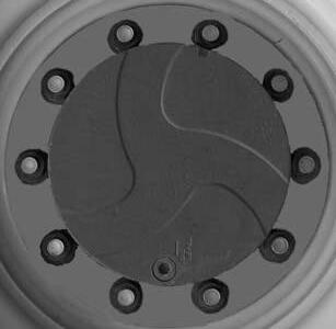
Before conducting any test port pressure checks, check the engine speed. Engine speed must be 1100 rpm at low idle and 2500 rpm at high idle.
NOTE: Pressure checks should be made with engine at low idle.
Steering Relief Pressure
Plug a 3000 psi (207 bar) oil-or liquid-filled gauge into the test port labeled ”SP.” Cramp the steering fully to the right or left. The gauge should read 2500 psi (172 bar).
Joystick and Parking Brake Release Pressure
Plug a 1000 psi (70 bar) gauge into the port labeled “JP.” With the engine running, the gauge should read 350 psi (24 bar).
Main Relief Pressure
Plug a 3000 psi (207 bar) oil-or liquid-filled gauge into the test port labeled “MP.” Fully retract the boom over the relief valve. The gauge should read 3000 psi (207 bar).
Change Hydraulic Reservoir Oil And Strainer
Clean all dirt and debris from around the top of the reservoir, especially around the access cover. Refer to illustration and use the following procedure:
4.Fill the reservoir with fresh oil. Follow specifications in the Lubrication chapter of this manual.
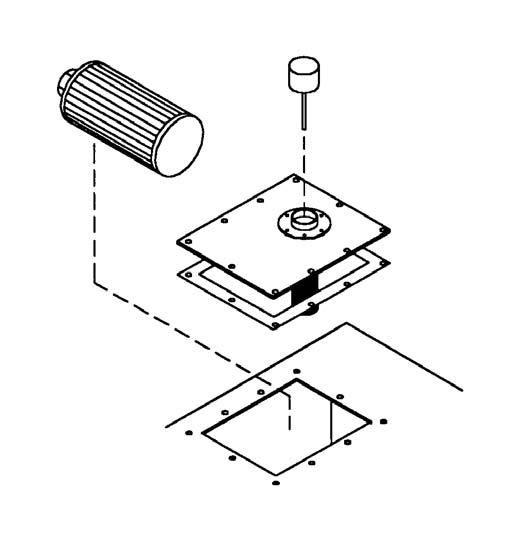
IMPORTANT: Hydraulic fluid and filters should be replaced any time contamination is present before the normally scheduled change.
Warning
NEVER use your hands to search for hydraulic fluid leaks. Escaping hydraulic oil under pressure can have sufficient force to penetrate the skin. Before applying pressure to the hydraulic system, be sure all connections are tight and lines and hoses are not damaged. Use a piece of wood or cardboard to search for suspected leaks. If injured by escaping hydraulic oil, see a doctor familiar with this type of injury at once or gangrene may result.
Change Radiator Coolant
Drain old coolant, flush the entire cooling system and fill with recommended coolant.
Drain the Coolant
IMPORTANT: DO NOT discharge coolant onto ground. Catch and dispose of per local waste disposal regulations.
1.Remove the drain plug and drain used oil. Wash or blow off all particles collected on the magnetic drain plug.
IMPORTANT: DO NOT discharge oil onto ground. Catch and dispose of per local waste disposal regulations.
2.Remove the access cover and wash the inlet screen with clean solvent. Remove and wash the sump filter strainer from the bottom inside of the reservoir. If the strainer has any damage, holes, etc., it should be replaced.
3.Flush out the bottom of the reservoir with clean hydraulic oil. Re-install all cleaned components and install the access cover on the reservoir with a new gasket. Clean the filter/breather cap.
Remove the radiator cap only when the engine is cool, or painful burns could result.
Follow this procedure to drain the coolant from the system:
1.Remove the radiator cap.
2.Drain the radiator by opening the drain valve at the bottom front of the radiator.
3.Working from under the right side of the engine, remove the drain plug at the bottom of the water inlet. See the following image for plug location.
4.Disconnect the EGR cooler coolant line to make sure coolant is drained from the EGR. This line is located on the left side of the engine as shown. Depending on accessiblity, the line can be disconnected on either end.
13.Follow Steps 7 - 8, then fill the system with water.
14.Operate the engine for 5 minutes with the coolant temperature above 176°F (80°C).
15.Shut the engine off and let it cool before draining the cooling system following Steps 2 - 4.
Filling the Cooling System
IMPORTANT: Fill the cooling system with a lowsilicate ethylene glycol based coolant mixed with quality water and supplemental coolant additives (SCAs) suitable for heavy-duty diesel engines. See the Lubrication chapter for engine coolant recommendations.
16.Follow Steps 7 - 9.
17.Open the cab heater valve if equipped.
18.Fill coolant to bottom of the radiator fill neck, (center of the sight glass).
19.Wait 2 to 3 minutess for air to vent from the system.
20.Repeat Steps 18 and 19 until the coolant level remains at the full level (center of the sight glass).
21.Start and run the engine 5 minutes to purge out remaining air.Heater should be on if equipped.
22.Turn off the engine, wait until coolant is below 122°F (50°C) to remove the radiator cap if installed.
5.Check for damaged hoses and loose or damaged hose clamps. Replace as required.
6.Check the radiator for leaks, damage and buildup of dirt. Clean and replace as required.
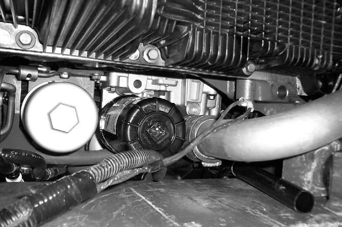
Flush the Cooling System
7.Close the radiator drain valve.
8.Install the drain plug in the water inlet.
9.Connect the EGR cooler coolant line.
10.Fill the cooling system with a mixture of sodium carbonate and water or a commercially available product such as Restore™ .
NOTE: Do not install the readiator cap.
11.Operate the engine for 5 minutes with the coolant temperature above 176°F (80°C).
12.Shut the engine off and let it cool before draining the cooling system following Steps 2 - 4.
23.Top off the coolant to bottom of the radiator fill neck (center of the sight glass).
24.Install the radiator cap and run the engine until it reaches a temperature of 176°F (80°C) and check for leaks.
25.Check the coolant level several times the first day after filling to be sure the coolant is at the correct level. Then check coolant level daily.
Refer to the Cummins engine Operation and Maintenance manual for additional coolant replacement instructions.
NOTE: Check the engine temperature gauge every minute or two after coolant has been changed. Air pockets can form and it may be necessary to refill the cooling system after a short period of use, as the air will naturally bleed out of the system.
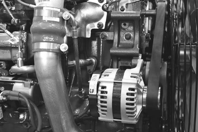
Check Coolant Hoses And Connections
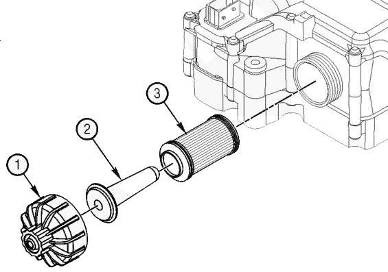
Check all coolant hoses for cuts, cracks or collapsing. Replace any damaged hoses.
NOTE: The silicone engine coolant hoses used on the machine will exhibit swelling due to the elesticity of the hose.
Service Every 4000 Hours or Three Years
Change Diesel Exhaust Fluid Dosing Unit Filter
The DEF dosing unit is located on the backwall of the battery compartment behind the DEF tank. The filter is located on the bottom of the dosing unit. Access to the filter can be gained through an opening in the battery compartment floor.
The aftertreatment DEF dosing unit filter consists of the following components:
Warning
Diesel exhaust fluid (DEF) contains urea. Do not get the substance in your eyes. In case of contact, immediately flush eyes with large amounts of water for a minimum of 15 minutes. Do not swallow. In the event the DEF is ingested, contact a physician immediately. Reference the Materials Safety Data Sheet (MSDS) for additional information.
Warning
The diesel exhaust fluid (DEF) line connecting the aftertreatment DEF dosing unit to the aftertreatment DEF dosing valve is under low pressure and should not be disconnected while the engine is running or before the system has completed the purge process after engine shutdown. Disconnecting the DEF line while under low pressure could cause DEF to spray.
DEF Dosing Unit Filter Removal
1.Aftertreatment dosing unit cap.
2.Aftertreatment dosing unit filter equalizing element.
3.Aftertreatment dosing unit filter element.
Inspect the area around the seal and vent of the aftertreatment DEF dosing unit filter cap for signs of leakage.
DEF leaks leave a white deposit. If deposits are found, see the Clean and Inspect for Reuse section in this procedure.
NOTE: Do not disconnect the vehicle batteries until the DEF dosing system has completed the purge cycle. Before beginning to remove and/or disconnect any components, wait at least five minutes after the keyswitch is turned OFF for the aftertreatment DEF dosing system to purge the DEF from the system. The purge cycle is an automatic process and does not require intervention to occur. The aftertreatment DEF dosing unit will create an audible pumping noise during the purging process.
Turn the battery disconnect switch to OFF and remove the key, then follow these removal instructions:
NOTE: There may be residual DEF in the filter housing. A collection container placed below the DEF filter cap is recommended.
1.Unscrew the DEF filter cap (1). A 27 mm wrench can be used on the cap to aid in removal.
2.Remove the aftertreatment DEF filter equalizing element (2).
3.Remove the old aftertreatment DEF dosing unit filter element (3). A disposable service tool is included with the filter to aid in filter removal. Use the appropriate end of the tool, depending on the color of the plastic on the filter. When inserting the tool, a "click" sound can be heard which indicates proper engagement with the filter.
DEF Dosing Unit Filter Installation
Slide the DEF filter equalizing element (2) into the DEF filter cartridge (3).
Insert the assembly into the aftertreatment DEF dosing unit.
Install and tighten the cap (1). A 27 mm wrench can be used to install and tighten the filter cap. Torque the cap to: 177 in-lb [20 Nm].
Storage
If the Telescopic Handler will not be operated for a period of three months or more, prepare and store it using the following procedure:
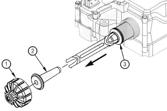
NOTE: If the storage area is outdoors or in a harsh environment, the storage procedure should be followed if the Telescopic Handler is to be stored for one month.
NOTE: If the filter element and equalizing element are removed from the aftertreatment DEF dosing unit, they must be discarded and replaced; regardless of condition.
Clean and Inspect DEF Cap for Reuse
1.Inspect the aftertreatment DEF dosing unit filter cap for cracks or holes that could create a DEF leak path.
2.Check the condition of the threads on the aftertreatment DEF dosing unit cap.
3.If the threads are damaged, replace the aftertreatment DEF dosing unit filter cap.
4.Inspect the aftertreatment DEF dosing unit threads. This is especially important if the aftertreatment DEF dosing unit cap was damaged.
5.If the aftertreatment DEF dosing unit threads are damaged, replace the entire aftertreatment DEF dosing unit.
NOTE: Never operate the vehicle with the DEF cap removed.
Clean the aftertreatment DEF dosing unit cap and threads on the dosing unit with warm water and a clean cloth.
Before Storage
Perform the following prior to placing the machine in storage:
1Wash the entire machine.
2.Lubricate all grease fittings as described in the Lubrication chapter of this manual.
3.Change engine oil as outlined in the Service and Storage chapter of this manual.
4.Apply grease to all exposed hydraulic cylinder rod areas.
5.Disconnect the battery cable clamps and cover the battery or remove the battery from the machine and store it separately.
6.If the ambient temperature (at any time during the storage period) is expected to drop below freezing, make sure the engine coolant is either completely drained from the radiator and engine block or that the concentration of anti-freeze is adequate to keep the coolant from freezing. Refer to the separate engine manual provided for anti-freeze recommendations and quantities.
During Storage
1.About once each month, connect the battery, check all fluid levels to make sure they are proper, and start the engine.
IMPORTANT: If it is desired to operate the hydraulic cylinders at this time, BE SURE to wipe the protective grease (and any adhering dirt) from the cylinder rods prior to starting the engine. After operating, BE SURE to recoat the cylinder rods with grease if the machine is to be returned to storage.
2.Allow the engine to run until it warms up and then move the machine a short distance to help relubricate the internal parts. Run the engine until the battery is recharged and then shut it off.
After Storage
After removing the machine from storage and BEFORE operating it, perform the following:
1.Change engine oil and filter to remove condensation and other residues.
2.Wipe off grease from cylinder rods.
3.Lubricate ALL grease fittings.
4.Follow the start-up and warm-up procedures outlined in the Operation and Adjustments chapter of this manual.


