19 minute read
Troubleshooting Guide


ProblemPossible CauseRemedy
Engine cranking speed too slow.
Check battery and charge/replace as necessary—tighten battery terminals. In cold temperatures, pre-warm the engine.
Fuel tank empty. Fill tank and vent fuel system if necessary.
Fuel filter plugged or restricted.Change fuel filter.
Fuel paraffin separation in winter.Use winter grade diesel fuel.
Fuel line leak. Tighten all threaded connections and clamps; replace fuel line as necessary.
Engine turns over but will not start
Fuel shut-off solenoid not energizing. Check electrical connections/voltage to shut-off solenoid.
Fuel filter restricted/fuel hose restriction. Replace filter/check for pinched fuel hose.
Fuel pump malfunction.Repair/replace fuel pump.
Water in fuel filter.Purge water from filter.
Fuel valve on water separator in the OFF position. Turn the valve to the ON position.
Engine fault code(s) displayed.Identify problem and correct.
Engine too cold/ambient temperature too low.
Pre-heating module malfunction; check connection and voltage and charge/ replace as necessary. Install block heater.
Troubleshooting Guide
ProblemPossible CauseRemedy
Crankcase oil level incorrect.Adjust oil level.
Cooling air circulation restricted.With engine off, remove restriction.
Fan shroud improperly positioned. With engine off, reposition shroud/ contact dealer.
Improper oil grade or oil excessively dirty. Change engine oil.
Exhaust restricted. Allow exhaust to cool; remove restriction.
Engine overheating
Air filter restricted.Replace filter(s).
Low coolant level.Top off coolant.
Loose fan belt.Tighten fan belt. Dirty/restricted radiator.Clean radiator.
Thermostat malfunction.Replace thermostat.
Engine overloaded.Reduce operating load.
Loose V-belt.Properly tension V-belt.
Blocked coolant hose.Find and remove obstruction.
Engine Components and Engine Controls - DPF Models
Engine Components and Engine Controls - Non-DPF Models
Air Cleaner and Exhaust Components - DPF Models
NOTE:
1. IF PRE CLEANER OPTION IS ORDERED WITH UNIT, SOUND DIFFUSER 192848 IS NOT USED.
Air Cleaner and Exhaust Components - Non-DPF Models
NOTE: IF PRE CLEANER OPTION IS ORDERED WITH UNIT, (192848) SOUND DIFFUSER CANNOT BE USED, RETURN TO INVENTORY
Radiator/Cooler Components - DPF Models
Radiator/Cooler Components - Non-DPF Models
NOTES:
1. IF SELF LEVEL OPTION IS USED, SHIFT BRACKET FROM TOWER TO OUTSIDE OF SELF LEVEL VALVE.
2. DISCARD FAN SPACERS THAT COME WITH THE ENGINE.
3. USE EXISTING FAN BOLTS THAT COME WITH THE ENGINE TO MOUNT THE FAN.
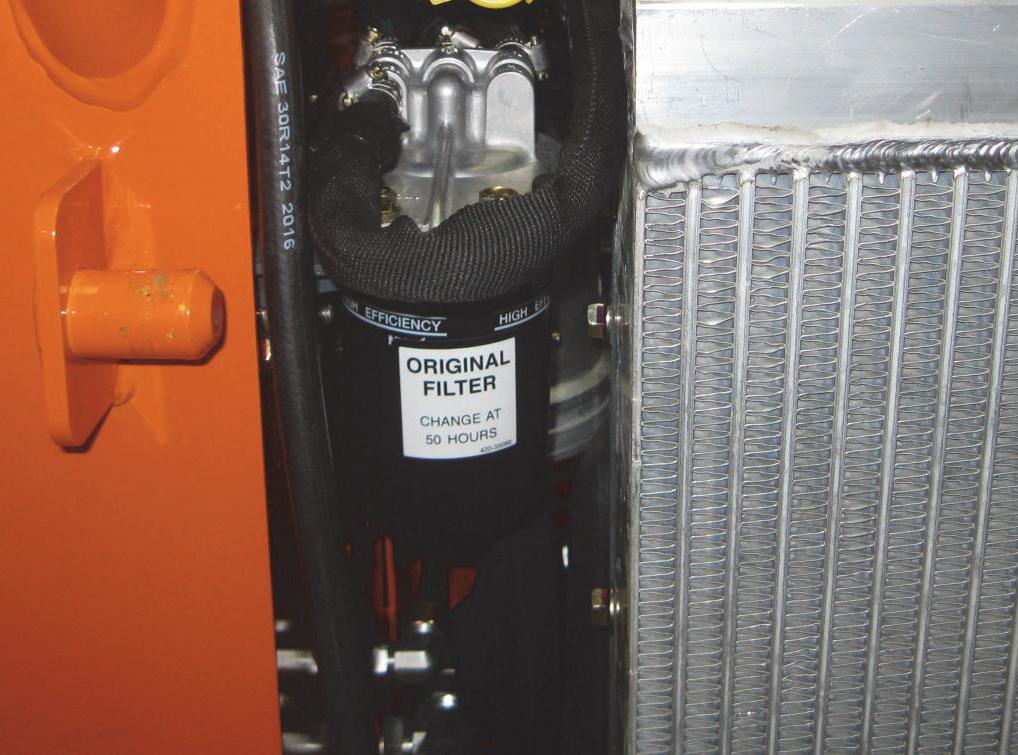
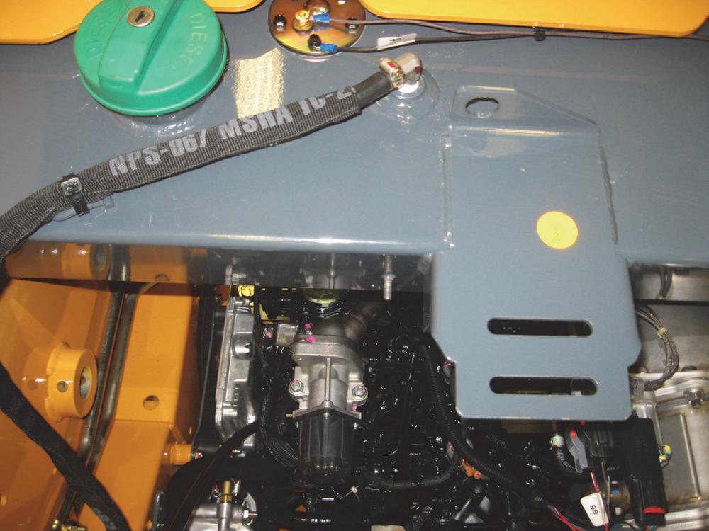
Oil Filter Element Removal and Installation
The engine oil filter is located on the left side of the engine and can be accessed through a belly pan in the chassis.
Warning
BEFORE beginning this service procedure, perform the following SAFETY procedures:
■ Shut off the engine and allow to cool.
(For detailed instructions, refer to the Safety chapter of this manual.)
Removal Procedure
1.Remove two capscrews on the rearmost belly pan and remove the pan.

4.Turning counterclockwise, loosen the oil filter element with a filter wrench.
5.Turn the filter element by hand until it is free of the oil filter mating surface.
Installation Procedure
1.Clean oil filter mating surface of any debris before installing new element.
2.Apply a thin film of oil to seal on filter element before installing.
3.Hand-tighten filter element, turning it clockwise, until gasket contacts filter mating surface, then turn element another 3/4 turn to seat gasket.
4.If old oil has been removed, fill crankcase with 7.6 qts. (7,2 L) of oil. (See Lubrication chapter.)
5.Start engine and check for leaks near oil filter. Shut off engine, recheck oil level, and fill as needed.
6.Replace the belly pan.
Air Cleaner Assembly Removal and Installation

Removal Procedure
Warning
BEFORE beginning this service procedure, perform the following SAFETY procedure:
■ Shut off the engine and allow to cool.
(For detailed instructions, refer to the Safety chapter of this manual.)
1.Open the engine access cover and lock open the rear grille.
2.Clean the area around the hose connection.
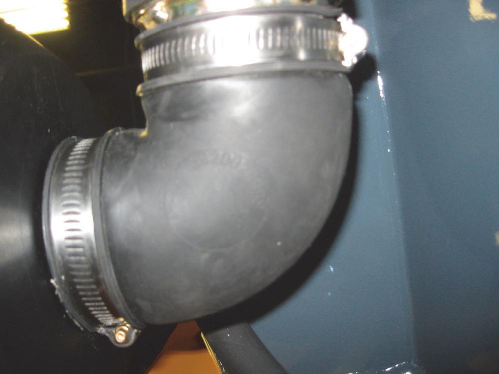
3.At the front of the air cleaner assembly, loosen the hose clamp securing the air filter hose to the assembly and pull the hose away from the air cleaner. Cover the air cleaner hose opening to help prevent contamination.
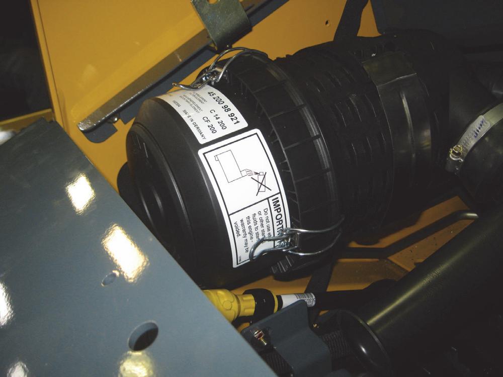
4.Loosen the hose clamp on the sound diffuser and remove the diffuser.
5.Remove the top capscrew and locknut securing the air cleaner bracket to the left riser to release the air cleaner canister.
6.Pull up on the bracket until it releases from itself and slide the air cleaner out of the bracket.
7.Remove the lower capscrew and locknut on the air cleaner bracket and remove the bracket.
Installation Procedure - Follow all warnings first, then reverse the removal steps.
Air Filter Element Removal and Installation
Service the air filter element when the restriction gauge shows in the red zone. The red zone indicates a clogged air filter. If the gauge shows red with the engine stopped, replace the air filter element. After fitting a clean element, push the gauge reset button.

Removal Procedure
Warning
BEFORE beginning this service procedure, perform the following SAFETY procedure:
■ Shut off the engine and allow to cool.
(For detailed instructions, refer to the Safety chapter of this manual.)
1.Open the engine access cover and lock open the rear grille.
2.Release the metal clips securing the air cleaner cover and remove the cover. Clean out any dirt build-up in the end cap.
3.Pull the primary and secondary air filters from the air cleaner assembly.

4.Replace both air filter elements, if needed. (See Service chapter of the Operator's Manual.)
5.Check the condition of the dust ejector. Installation Procedure - Follow all warnings first, then reverse the removal steps.*
* Clean the radial seal surfaces of the mating plastic body.
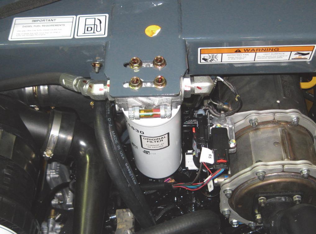
Fuel Filter Removal and Installation
The fuel filter is a maintenance item in the fuel system.
Removal Procedure
1.Shut off the fuel supply by turning a valve on the water separator.

Adding Fuel
The fuel tank is filled at the factory with United States off-road grade diesel fuel, dyed red for identification.
Warning
BEFORE beginning this service procedure, perform the following SAFETY procedures:
2.Remove the fuel filter.
■ Keep open flames and sparks away from fuel. Static electricity can produce dangerous sparks at the fuel-filling nozzle. Do not wear polyester, or polyester-blend clothing while fueling. Before fueling, touch the metal surface of the machine away from the fuel fill to dissipate any built-up static electricity. Do not re-enter the machine but stay near the fuel filling point during refueling to minimize the build-up of static electricity. Do not use cell phones while fueling. Make sure the static line is connected from the machine to the fuel truck before fueling begins.
■ Ultra-Low Sulfur Diesel (ULSD) poses a greater static ignition hazard than earlier diesel formulations. Avoid death or serious injury from fire or explosion; consult with your fuel or fuel system supplier to ensure the entire fuel delivery system is in compliance with fueling standards for proper grounding and bonding practices.
Installation Procedure
1.Lubricate the new fuel filter gasket with diesel fuel.
2.Install and turn the filter one-half turn past the point where the gasket contacts the filter head.
3.Turn the valve on the water separator to allow the diesel fuel to flow through the filter.
NOTE: When the fuel filter is changed, the system MUST BE primed.
1.Perform the “Mandatory Safety Shutdown Procedure” found in the Safety Chapter.
2.Open the engine access cover and lock open the rear grille. The fuel cap is located under the engine cover.
3.Use the ignition key to unlock fuel cap and remove the fuel cap from the fuel filler neck.
4.Fill the fuel tank by adding fuel through the fuel filler neck opening.
5.When the tank if full, replace and lock the fuel cap in the fuel filler neck opening.
IMPORTANT: To provide for proper fuel system venting, do not top off the fuel tank.
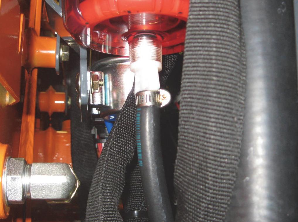
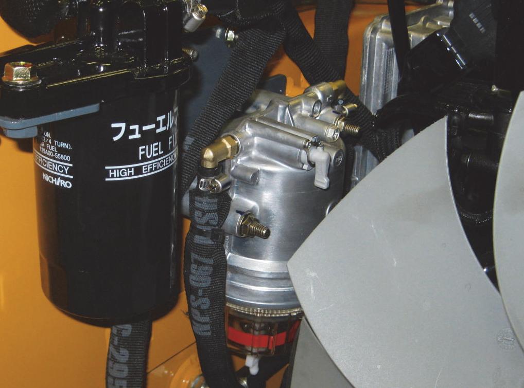
Water Separator Maintenance WARNING
BEFORE beginning this service procedure, perform the following SAFETY procedures:
■ Shut off the engine and allow to cool.
■ NEVER service the fuel system while smoking, while near an open flame, or if the engine is hot.
(For detailed instructions, refer to the Safety chapter of this manual.)
IMPORTANT: Water in the fuel system can cause severe engine damage. Drain the water from the fuel filter/water separator whenever water is present.

1.Inspect the water separator for the presence of water.
If the indicator ring (M) is floating off the bottom of the cup, water is present and needs to be drained.
2.If water needs to be drained, position a suitable collection container underneath the water separator drain.
3.Turn the fuel valve lever (V) on the water separator to the OFF position.
4.Loosen drain plug (N) at the bottom of the water separator. Allow water to drain until indicator ring falls to the bottom of the cup.
5.Tighten drain plug (N) and discard fuel/water according to environmental laws.
IMPORTANT: Dispose waste fuel according to environmental laws. DO NOT pour fuel onto the ground or down a drain.
6.Turn the fuel valve lever (V) on the water separator to the ON position.
7.Prime the fuel system by turning the ignition key to the ON position without starting the engine for 30 seconds. Repeat this step 3 times to ensure the fuel system is completely primed.
Caution
Do not use the starter motor to crank the engine to prime the fuel system. Damage to the engine starter motor, coils, pinion/ring gear could result.
8.Start the engine and check for leaks.
If the indicator ring (M) is at the bottom of the cup, no action is required.
Changing the Water Separator Filter WARNING
BEFORE beginning this service procedure, perform the following SAFETY procedures:
■ Shut off the engine and allow to cool.
■ NEVER service the fuel system while smoking, while near an open flame, or if the engine is hot.
(For detailed instructions, refer to the Safety chapter of this manual.)
1.Turn the fuel valve lever (V) on the water separator to the OFF position.
2.Unscrew the separator bowl from the housing and pull down on the existing filter to release it from the housing.
3.Install a new filter and reinstall the bowl.
4.Turn the fuel valve lever (V) on the water separator to the ON position.
5.Prime the fuel system by turning the ignition key to the ON position without starting the engine for 30 seconds. Repeat this step 3 times to ensure the fuel system is completely primed.
Caution
Do not use the starter motor to crank the engine to prime the fuel system. Damage to the engine starter motor, coils, pinion/ring gear could result.
6.Start the engine and check for leaks.
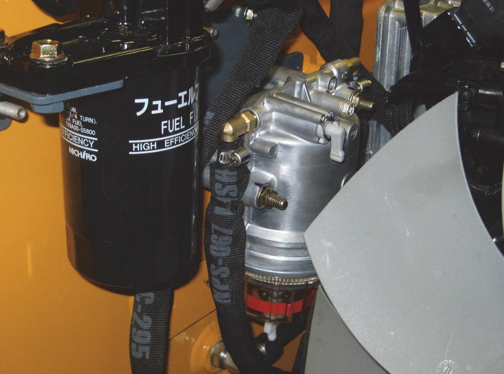
Changing the Fuel Filter WARNING
BEFORE beginning this service procedure, perform the following SAFETY procedures:
■ Shut off the engine and allow to cool.
■ NEVER service the fuel system while smoking, while near an open flame, or if the engine is hot.
(For detailed instructions, refer to the Safety chapter of this manual.)
IMPORTANT: Change the fuel filter every 250 hours of operation.
1.Turn fuel valve lever (V) on the water separator to the OFF position.
2.Remove the fuel filter (W) using a filter wrench if necessary. Carefully clean the filter head mounting surface with a clean cloth.
3.Apply a coating of clean diesel fuel on the new fuel filter gasket. Install the filter and tighten 3/4 rotation past the point where the gasket contacts the filter head.
4.Turn fuel valve (V) on the water separator to the ON position.
5.Prime the fuel system by turning the ignition key to the ON position without starting the engine for 30 seconds. Repeat this step 3 times to ensure the fuel system is completely primed.
Caution
Do not use the starter motor to crank the engine to prime the fuel system. Damage to the engine starter motor, coils, pinion/ring gear could result.
6.Start the engine and check for leaks.
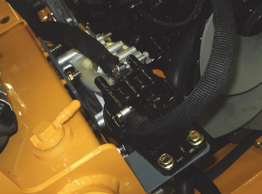
Electric Fuel Pump Removal and Installation
The electric fuel pump is located between the water separator and the fuel filter on the left inside riser, very close to the water separator.
Removal Procedure
1.Unplug the electrical connector on the fuel pump.
Priming the Diesel Fuel System
When the fuel filter is changed or if the diesel engine runs out of fuel, the system MUST BE primed.
Priming Procedure
1.Turn the keyswitch to the ON position to charge the electric fuel pump.
2.Air is vented through the excess fuel return line to the fuel tank. There is not vent plug to open.
3.Leave the keyswitch in the ON position until air is no longer heard being released in the fuel tank.
2.Shut off the fuel supply by turning the fuel shutoff valve on top of the water separator.
3.Loosen two small hose clamps at the top and bottom of the fuel pump.
4.Remove two locknuts securing the fuel pump to the chassis.
5.Slip the fuel hoses off of the fuel pump and plug the hoses.
Installation Procedure
1.Slip the new electric fuel pump (with the electrical connector positioned lower) over the bolts in the chassis and tighten with locknuts.
2.Unplug the fuel hoses and connect at top and bottom of the fuel pump and secure with hose clamps.
3.Plug the fuel pump’s electrical connector at its connection in the engine harness.
4.Turn the valve on the water separator to allow the diesel fuel to flow through the filter.
Battery Removal and Installation
Removal Procedure
Warning
BEFORE beginning this service procedure, perform the following SAFETY procedure:
■ Shut off the engine and allow to cool. (For detailed instructions, refer to the Safety chapter of this manual.)
Warning
Review the following safety considerations before working on or around the battery:
■ Keep sparks and flames away from battery. Gas given off by the battery’s electrolyte solution is extremely explosive.
■ Avoid contact with battery electrolyte; wash off any electrolyte immediately.
■ Wear safety glasses when working near battery.
■ Do not tip battery more than 45° to avoid spilling electrolyte solution.
■ To avoid injury from spark or short circuit, disconnect negative (-) battery cable before servicing electrical system.

1.Open the engine access cover and lock open the rear grille.
2.First, disconnect and remove the negative (-) battery cable and then disconnect the positive (+) battery cable from the battery.
4.Lift the battery up and out of the chassis. Installation Procedure - Follow all warnings first, then reverse the removal steps.
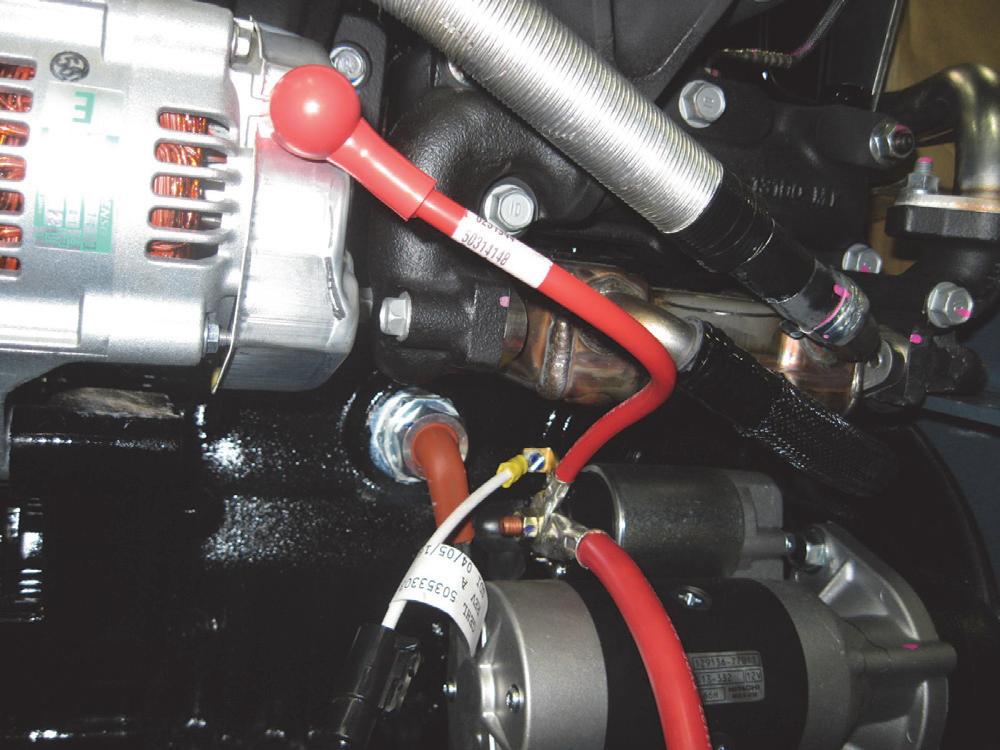
Starter Removal and Installation
For wiring connections to the starter and solenoid, refer to the Electrical System chapter of this manual.

Removal Procedure
Warning
BEFORE beginning this service procedure, perform the following SAFETY procedures:
■ Remove attachment from lift arm.
■ Raise lift arm, engage lift arm support device.
■ Shut off the engine.
■ Tilt back ROPS/FOPS until lock engages.
˘ (For detailed instructions, refer to the Safety chapter of this manual.)
1.Open the engine access cover and lock open the rear grille.
2.Disconnect and remove the negative (-) battery cable from the battery.
3.On the starter solenoid, remove the nut that secures the positive (+) battery cable and a smaller wire. Also, disconnect the push-on connector attached at the solenoid.
4.Remove the two capscrews securing the starter to the engine.
5.Remove the starter from the engine. Installation Procedure - Follow all warnings first, then reverse the removal steps.
Exhaust Assembly Removal and Installation - Non-DPF Models
Removal Procedure
Warning
BEFORE beginning this service procedure, perform the following SAFETY procedures:
■ Lower the lift arm completely.
■ Shut off the engine and allow to cool.
(For detailed instructions, refer to the Safety chapter of this manual.)
1.Open the engine access cover and lock open the rear grille.
2.Remove
Installation Procedure - Follow all warnings first, then reverse the removal steps.*
*Tighten the mounting hardware only after checking the alignment of the exhaust assembly so that the tailpipe is centered in the opening on the engine cover when closed.
Exhaust Tube Removal and InstallationDPF Models
Removal Procedure
Warning
BEFORE beginning this service procedure, perform the following SAFETY procedures:
■ Lower the lift arm completely.
■ Shut off the engine and allow to cool.
(For detailed instructions, refer to the Safety chapter of this manual.)
1.The exhaust tube is connected to the DPF cannister.


Installation Procedure - Follow all warnings first, then reverse the removal steps.*
*Tighten the mounting hardware only after checking the alignment of the exhaust assembly so that the tailpipe is centered in the opening on the engine cover when closed.
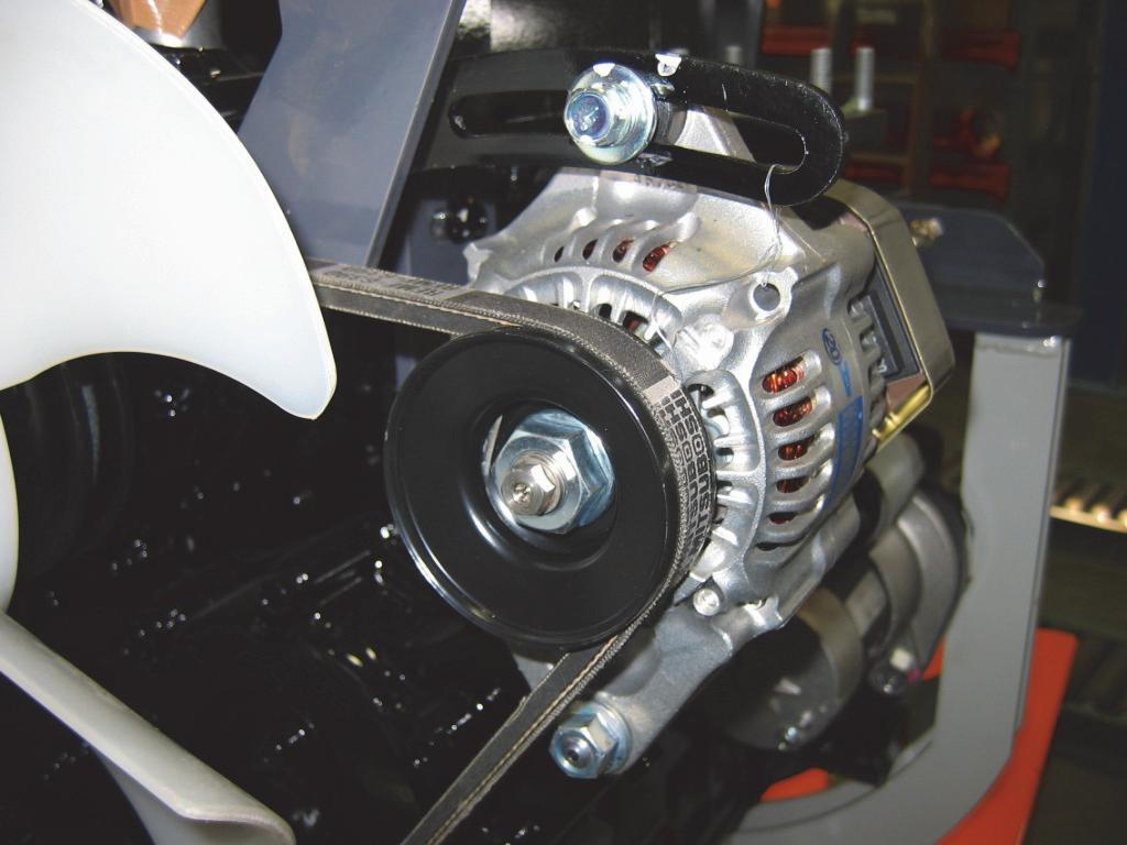
Fan Belt Adjustment Adjustment Procedure
Warning
BEFORE beginning this service procedure, perform the following SAFETY procedure:
■ Shut off the engine and allow to cool. (For detailed instructions, refer to the Safety chapter of this manual.)
1.Open the engine access cover and lock open the rear grille.
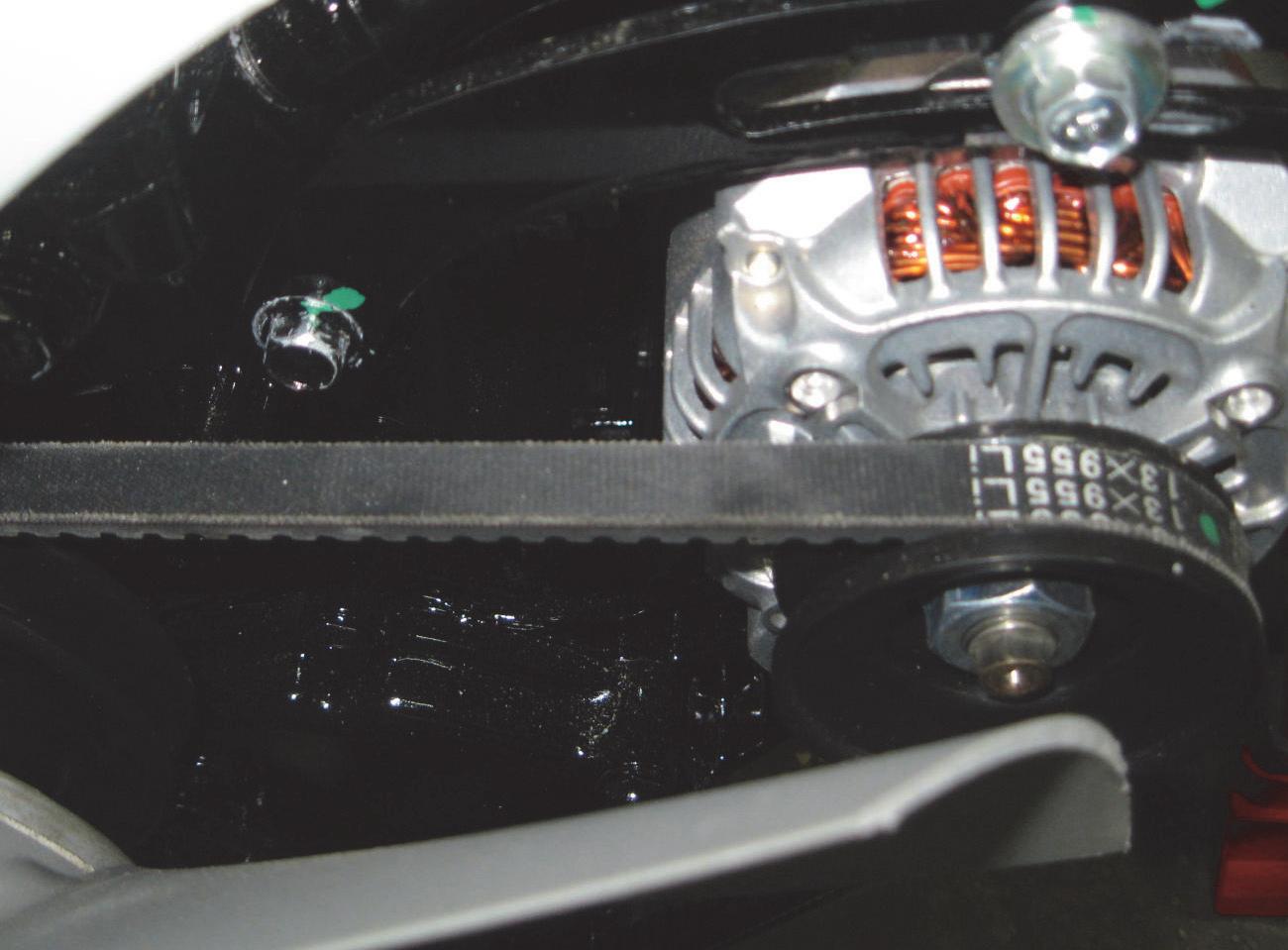
2.Test the fan belt tension by pushing on the belt midway between the alternator and the engine crankshaft pulley. The belt should deflect about ½" (13 mm) under a load of 20 lbs. (90 N). If adjustment is needed, follow the next steps.
4.Rotate the alternator in a clockwise direction (viewed from the engine end) until the correct belt tension is achieved.
5.Retighten the bolts.
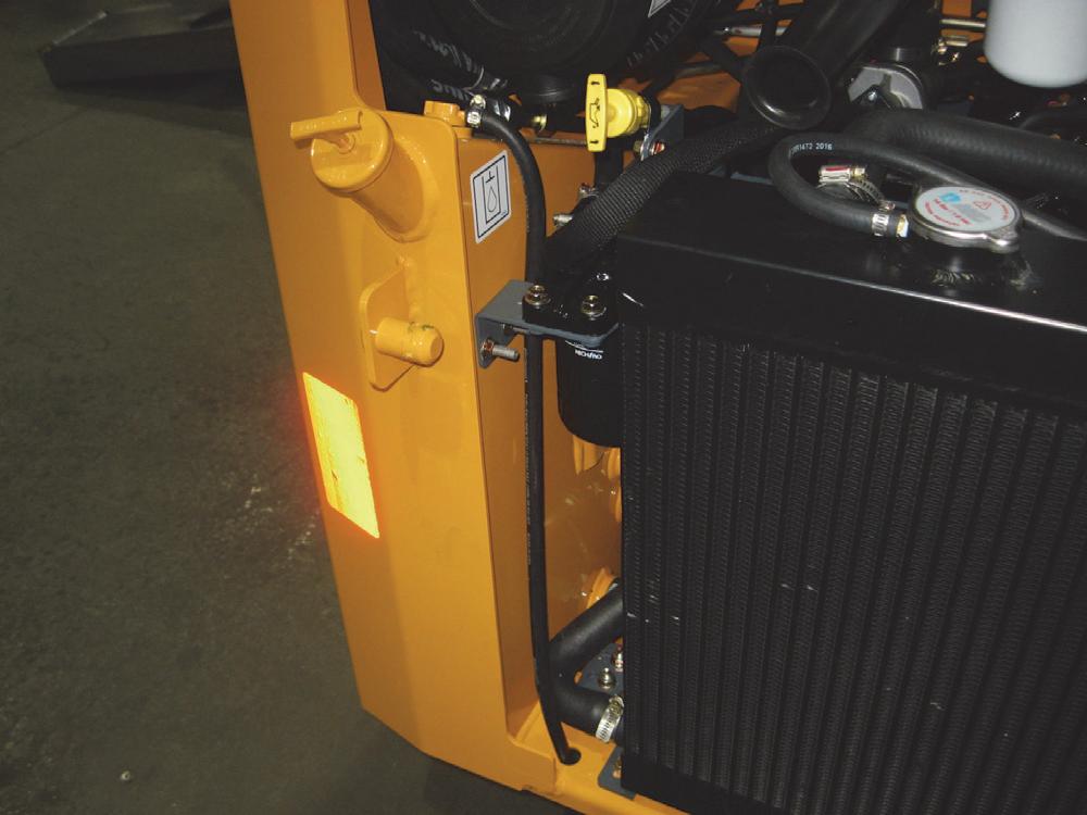
Radiator/ Oil Cooler Removal and Installation
The radiator/oil cooler is mounted on a shroud located just behind the engine.

Removal Procedure
Warning
BEFORE beginning this service procedure, perform the following SAFETY procedure: connect the hose clamps on the radiator hoses and the hydraulic oil lines from their fittings.
■ Shut off the engine and allow to cool.
(For detailed instructions, refer to the Safety chapter of this manual.)
1.If necessary, drain the oil from the hydraulic reservoir per the procedure in the Lubrication chapter.

2.If necessary, drain the engine coolant from the radiator per the procedure in the Lubrication chapter.
NOTE: Hydraulic oil lines should be plugged to prevent contaminants from entering the hydraulic system. If the hydraulic oil lines are plugged after removal to prevent oil leakage, it should not be necessary to drain the hydraulic reservoir.
3.Open the engine access cover and lock open the rear grille.
4.Disconnect the recovery tanks hose leading to the overflow bottle at the radiator cap.
5.Remove coolant hoses and hydraulic oil lines from the inlets and outlets of the radiator/oil cooler. Dis-

NOTE: BE SURE to use two wrenches on the hydraulic oil lines, one on the oil cooler fitting and the other on the hydraulic oil line to prevent damage to the oil cooler.
6.Remove remote radiator overflow line at the top of the radiator.
7.Remove three locking capscrews on each side securing the radiator/oil cooler tab to the shroud.
Fan Shroud and Support Brackets
Removal and Installation
Removal Procedure
Warning
BEFORE beginning this service procedure, perform the following SAFETY procedure:
■ Shut off the engine and allow to cool.
(For detailed instructions, refer to the Safety chapter of this manual.)
8.Using a suitable hoist of adequate capacity and a positive locking mechanism able to support the radiator/oil cooler or equivalent, remove the radiator/oil cooler from the skid-steer loader.
Installation Procedure - Follow all warnings first, then reverse the removal steps.
Warning
NEVER use your hands to search for hydraulic fluid leaks. Use a piece of cardboard or paper. Escaping fluid under pressure can be invisible and penetrate the skin causing serious injury. If any fluid is injected into your skin, see a doctor at once. Injected fluid MUST be surgically removed by a doctor familiar with this type of injury or gangrene may result.
Warning
ALWAYS wear safety glasses when checking for hydraulic fluid leaks. Escaping fluid under pressure can be invisible and can cause permanent eyesight damage if safety glasses are not worn.
9.ALWAYS check for hydraulic fluid leaks after installing any components of the hydraulic system.
Warning
DO NOT attempt to service any part of radiator/oil cooler system until engine has been allowed to cool. Serious injury may result from high temperature oil or water coolant or high pressure.
1.Remove the hydraulic reservoir drain plug and drain the hydraulic oil into a suitable container. Refer to the procedure in the Lubrication chapter.
NOTE: Hydraulic oil lines should be plugged after disconnecting to prevent contaminants from entering the hydraulic system. If the hydraulic lines are plugged after disconnecting to prevent leakage, it should not be necessary to drain the hydraulic reservoir.

2.Remove the radiator/oil cooler per the procedure in this chapter.
3.Underneath the skid-steer loader there is space to access and remove two locknuts securing the shroud support brackets to a bracket on the floor of the chassis, on each side of the skid-steer loader.

Fan Shroud Adjustment Adjustment Procedure

Warning
BEFORE beginning this service procedure, perform the following SAFETY procedure:
■ Shut off the engine and allow to cool. (For detailed instructions, refer to the Safety chapter of this manual.)
1.Loosen, but do not remove, the two locking capscrews on the shroud support connected to the shroud.
5.Unbolt the shroud supports at this time, if necessary.
Installation Procedure - Follow all warnings first, then reverse the removal steps.*
* BE SURE and uncap/unplug the hydraulic oil lines prior to reconnecting them to the radiator/oil cooler.
2.Move the shroud and radiator/oil cooler assembly up or down until the fan is centered in the shroud opening.

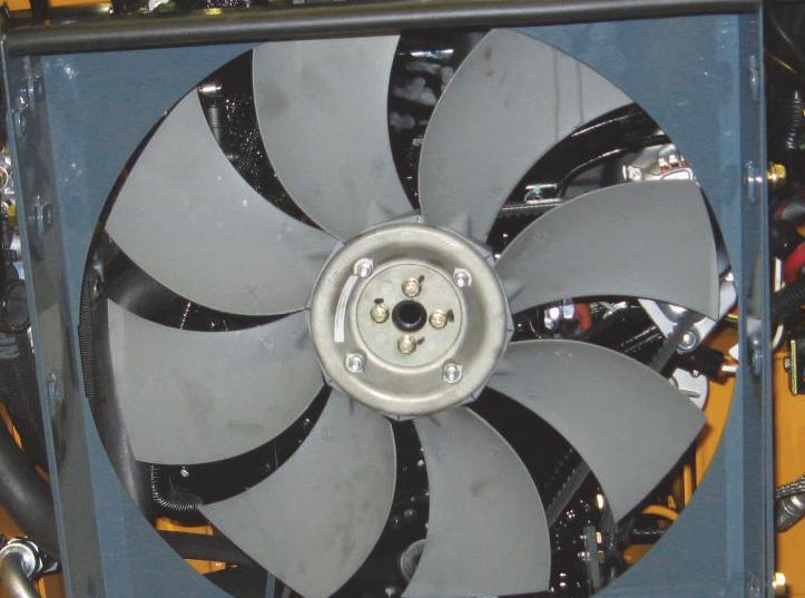
Fan Removal and Installation
Removal Procedure
Warning
BEFORE beginning this service procedure, perform the following SAFETY procedure:
■ Shut off the engine and allow to cool.
(For detailed instructions, refer to the Safety chapter of this manual.)
1.If necessary, drain the oil from the hydraulic reservoir per the procedure in the Lubrication chapter.
2.If necessary, drain the engine coolant from the radiator per the procedure in the Lubrication chapter.
NOTE: Hydraulic oil lines should be plugged to prevent contaminants from entering the hydraulic system. If the hydraulic oil lines are plugged after removal to prevent oil leakage, it should not be necessary to drain the hydraulic reservoir.
3.Remove the radiator/oil cooler per the procedure in this chapter.
4.Unbolt four nuts securing the fan to the engine.
Fuel Tank Removal
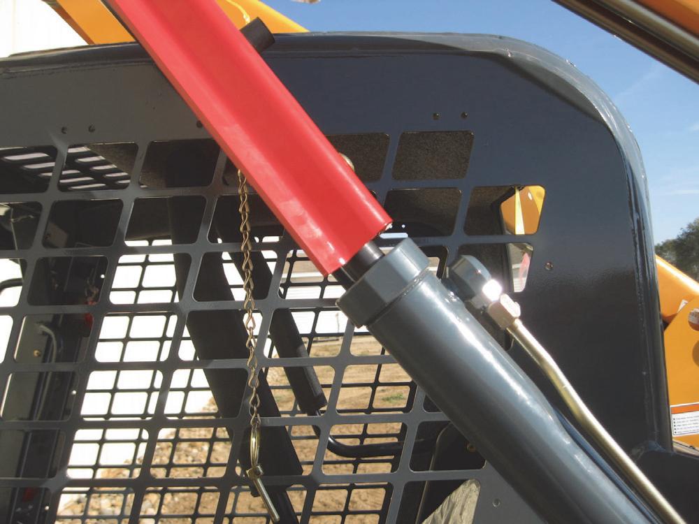
The welded-steel fuel tank on Gehl R105 and Mustang 1050R skid-steer loaders is nestled in a chassis crossmember behind the ROPS/FOPS.
Removal Procedure
Warning
BEFORE beginning this service procedure, perform the following SAFETY procedure:
■ Remove attachment from lift arm.
■ Raise lift arm; engage lift arm support device.
■ Shut off the engine and allow to cool.
■ Tilt back ROPS/FOPS until lock engages. (For detailed instructions, refer to the Safety chapter of this manual.)
1.Open the engine access cover and lock open the rear grille.
2.Remove the air cleaner assembly per the procedure found in this chapter.
3.Turn the water separator fuel shut off valve to its OFF position.
5.Carefully pull the fan out the rear of the skid-steer loader.
6.Repair or replace the engine fan. Installation Procedure - Follow all warnings first, then reverse the removal steps.
4.Loosen the clamp on the fuel supply hose on the outside of the water separator. Place the hose end in an approved container with enough capacity (9.5 gal.) (36 L) to hold a full tank of fuel.
5.Loosen the fuel cap on the fuel tank and drain the diesel fuel into the approved container.
6.Reinstall the fuel supply hose to the water separator.
7.Loosen the hose clamps on two hose lines at the top and bottom of the fuel tank and pull the hoses off the barbed fittings.
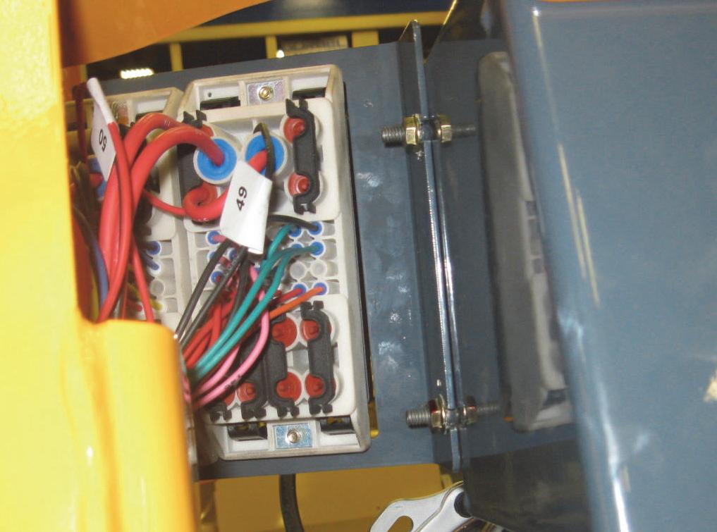
10.Remove two nuts holding the fuse panel at the right side of the fuel tank.

NOTE: Cap or plug all hydraulic hoses and tubes immediately after they are disconnected to prevent fluid loss and contamination of the hydraulic system.
11.Remove the capscrews securing the hydraulic filter assembly to the fuel tank welded tab.
12.Remove locknuts on carriage bolts securing the fuel tank bracket to the left side of the chassis riser.
8.Remove the fuel sender wiring and fuel sender per the procedure in the Mainframe chapter.
9.Remove
13.Remove locking capscrews at the front of the fuel tank securing the tank to the chassis crossmember.

14.Maneuver the tank out of the chassis.
Installation Procedure* - Follow all warnings first, then reverse the removal steps.
* Perform the “Priming Diesel Fuel System” procedure in this chapter after the re-connection of the fuel tank.
Engine Removal and Installation
The following procedure allows removal of the diesel engine without removing the hydrostatic pump assembly. Some hydraulic hoses/oil lines need to be disconnected in this procedure, and if they cannot be capped/plugged to prevent fluid loss, the hydraulic reservoir should be drained BEFORE disconnecting any hydraulic hoses/oil lines.

Removal Procedure
Warning
BEFORE beginning this service procedure, perform the following SAFETY procedures:
■ Raise lift arm; engage lift arm support device.
■ Shut off the engine.
(For detailed instructions, refer to the Safety chapter of this manual.)
1.Drain the hydraulic oil reservoir and the engine oil.
2.Remove the floor covers and kickplate per the procedure in the Mainframe chapter.
3.Remove the rear grille per the procedure in the Mainframe chapter.
4.Remove the ROPS/FOPS per the procedure found in the Mainframe chapter.
5.Remove the battery per the procedure in this chapter.
6.Remove the air cleaner assembly per the procedure in this chapter.
Warning
DO NOT PROCEED with the following steps unless engine has completely cooled and is safe to touch.
7.Remove the exhaust assembly per the procedure in this chapter.
8.Remove the radiator/oil cooler per the procedure in this chapter.
9.Remove the fan shroud and support brackets per the procedure in this chapter.
13. Non-DPF Models Only: Remove the hand throttle cable and engine throttle cable per the “Handle Throttle, Hand Throttle Cable and Throttle Rod Removal and Installation” procedure in the Controls chapter.
14.Unplug engine harness connectors located in several areas on the engine and attached to the chassis.


NOTE: The following step includes disconnection of hydraulic hoses. If hoses cannot be capped/plugged to prevent fluid loss, the hydraulic reservoir should be drained BEFORE disconnecting hoses. Refer to the Hydraulic System chapter for the procedure.
NOTE: ALWAYS clean area around hydraulic fittings BEFORE disconnecting any hydraulic hose or tube.

15.Label and disconnect all the hydraulic hoses connected to the hydrostatic pump. Refer to the “Hydrostatic Pump Removal” procedure in the Hydrostatic System chapter for hydraulic hose removal procedure on the pump.

16.Disconnect the negative (-) battery cable from the engine, located beneath the engines starter.
17.On the starter solenoid, remove the nut that secures the positive (+) battery cable and a smaller wire. Also, disconnect the push-on connector attached at the solenoid.
18.Attach lift hooks to engine lifting locations on the front and rear of the cylinder head.
19.Remove one capscrew, lock nut (110 ft-lbs) (149 N•m) and three washers on two forward engine mounts.

20.Remove one capscrew, locknut (55 ft-lbs) (75 N•m) and two washers on the rear engine mount.
Warning
NEVER use your hands to search for hydraulic fluid leaks. Use a piece of cardboard or paper. Escaping fluid under pressure can be invisible and penetrate the skin causing serious injury. If any fluid is injected into your skin, see a doctor at once. Injected fluid MUST be surgically removed by a doctor familiar with this type of injury or gangrene may result.
21.Using a suitable hoist of adequate capacity and a positive locking mechanism able to support the engine, lift slightly and pull the engine rearward. Continue pulling the engine rearward until the pump is free from the drive coupling, then remove the engine from the chassis.
Warning
ALWAYS wear safety glasses when checking for hydraulic fluid leaks. Escaping fluid under pressure can be invisible and can cause permanent eyesight damage if safety glasses are not worn.
ALWAYS check for hydraulic fluid leaks after installing any components of the hydraulic system.
Engine Diagnostic Chart (DPF Models)
When detecting faults, the information center electronic display uses a diagnostic trouble code (DTC) screen to alert the operator to the occurrence of the fault conditions.
The data port for accessing the diagnostic trouble codes can be found underneath an electrical cover, right of the seat.

Installation Procedure - Follow all warnings first, then reverse the removal steps.*
* Bleed the fuel system. Also check engine oil and hydraulic oil levels prior to starting the engine.
* If the diesel fuel was drained, add fuel, then prime the fuel system according to the “Priming Diesel Fuel System” procedure in this chapter.
* Safely check for hydraulic fluid leaks observing the correct procedure in doing so (refer to Hydraulic System chapter).
* Perform the neutral centering adjustment procedure found in the Controls chapter.

Engine Diagnostic Trouble Codes (DTC)
Table1:YanmarEngineDiagnosticTroubleCodes(DTC)