20 minute read
Troubleshooting Guide


ProblemPossible CauseRemedy
Lift arm will not raise a heavy load or any load Lift solenoid malfunctioning
Lift spool in control valve not actuated or leaking
Main relief valve malfunctioning (squealing noise evident while operating)
Check electrical connections to solenoid. Repair or replace as needed.
Check valve body for scores or cracks. Replace control valve as needed.
Check pressures in relief valve. Repair or replace as needed.
Bucket does not level on the lift cycle
Self-leveling valve misadjusted or malfunctioning
Bucket will not tilt; lift arm works properly Tilt solenoid valve malfunctioning Tilt spool in control valve not actuated or leaking
Auxiliary hydraulics functions slowly
Control linkage misadjusted
Low engine speed
Hydraulic oil level low
Hydraulic oil viscosity too heavy
Control valve relief pressure low
Auxiliary hydraulics do not functionRestraint bar raised
Restraint bar switch or seat switch malfunctioning
Blown fuse or relay
Faulty electrical connections
Repair or replace self-leveling valve as needed.
Check electrical connections to tilt solenoid and repair connections as needed. Replace solenoid as needed.
Check hose or tube connection to valve. Check pressure and flow.
Check linkage; readjust for full spool travel.
Operate engine at higher speeds. Add oil to reservoir.
Allow for longer warm-up period.
Check pressure at control valve. Readjust if necessary.
Lower restraint bar
Replace malfunctioning switch
Replace fuse or relay.
Check electrical connections for security, broken or damaged wires. Replace as needed.
Solenoid valve malfunctioning
Check electrical connections to solenoid. Repair or replace as needed.
Chapter Notes
Introduction
Description of Operation - Instrument Panel - DPF Models
The instrument panel for Gehl R105 and Mustang 1050R DPF model skid-steer loaders includes a parking brake switch, engine preheat switch, light switch, 12VDC power outlet and keyswitch.
The instrument panel contains the following switches and indicators. Symbols on the panel represent various functions and conditions, and are visible only when indicator lamps are on.
1.Keyswitch – In a clockwise rotation, these positions are:
OFF Position – With the key vertical, power from the battery is disconnected from the controls and instrument panel electrical circuits. This is the only position from which the key can be inserted or removed.
ON (or RUN) Position – With the key turned one position clockwise from vertical, power from the battery is supplied to all control and instrument panel circuits.
START Position – With the key turned fully clockwise, the electric starter engages, to start the engine. Release the key to RUN position after the engine starts.
NOTE: The engine cannot be started unless the operator is sitting in the seat and the restraint bar is lowered. To verify that the seat and restraint bar switches are working properly, after the keyswitch is turned to ON, raise the restraint bar or lift body off the seat. Either action should prevent the engine from cranking with the keyswitch turned to START.
2.Information Center Electronic Display.
3.Fuel Level Gauge – Displays the amount of fuel in the tank.
4.Fasten Seatbelt – A momentary visual (and audible) indicator to remind the operator to fasten the seatbelt.
5.Engine Oil Pressure – Lights if the engine oil pressure drops too low, warning the operator to immediately stop the engine and determine the cause for the pressure drop. During normal operation, this indicator should be OFF
6.Battery – Lights if the charging voltage is too high or too low. During normal operation, this indicator should be OFF.
7.Preheat Indicator Lamp – Lights when the (automatic) preheat is active. During normal operation this indicator should be OFF.
8.Engine Malfunction Lamp – Indicates the engine ECU has detected a malfunction of the engine.
9.Engine Coolant Temperature – Lights if the engine coolant becomes too hot, warning the operator to stop the engine. Allow the engine to cool, determine the cause for the high temperature and correct the problem before restarting the engine. During normal operation, this indicator should be OFF.
10.Hydraulic Oil Temperature – Lights if the hydraulic oil becomes too hot, warning the operator to stop engine. Allow the hydraulic system to cool and determine the cause of the high temperature. During normal operation, this indicator should be OFF.
11.Parking Brake Switch – Used to manually apply the parking brake. Lights when the parking brake is applied.
12.Engine Speed Control – Controls the engine speed. Move the control clockwise to increase and counter-clockwise to decrease the engine speed.
13.Light Switch – Controls all the lights on the loader. Symbols denote the four positions of the light switch. In a clockwise direction these are:
Front Work Lights with Tail Lights ON both Front and Rear Work Lights
For the lights to function, the keyswitch must be in the RUN position.
14.Accessory Outlet – 12-volt DC power outlet.
Notes
Description of Operation - Instrument Panel - Non-DPF Models
The instrument panel for Gehl R105 and Mustang 1050R Non-DPF model skid-steer loaders includes a parking brake switch, engine preheat switch, light switch, 12-VDC power outlet and keyswitch.
The instrument panel contains the following switches and indicators. Symbols on the panel represent various functions and conditions, and are visible only when indicator lamps are on.
1.Hourmeter – Displays the total operating hours on the loader.
2.Fuel Level Gauge – Displays the amount of fuel in the tank.
3.Engine Coolant Temperature Gauge – Indicates the engine coolant temperature.
NOTE: Items 4 through 9 are indicator lamps which display the following:
4.Fasten Seatbelt – A momentary visual (and audible) indicator to remind the operator to fasten the seatbelt.
5.Engine Oil Pressure – Lights if the engine oil pressure drops too low, warning the operator to immediately stop the engine and determine the cause for the pressure drop. During normal operation, this indicator should be OFF.
6.Battery – Lights if the charging voltage is too high or too low. During normal operation, this indicator should be OFF.
7.Preheat Indicator Lamp – Lights when the preheat switch is pressed. During normal operation, this indicator should be OFF.
8.Engine Coolant Temperature – Lights if the engine coolant becomes too hot, warning the operator to stop the engine. Allow the engine to cool, determine the cause for the high temperature and correct the problem before restarting the engine. During normal operation, this indicator should be OFF.
9.Hydraulic Oil Temperature – Lights if the hydraulic oil becomes too hot, warning the operator to stop engine. Allow the hydraulic system to cool and determine the cause of the high temperature. During normal operation, this indicator should be OFF.
10.Keyswitch – In a clockwise rotation, these positions are:
OFF Position – With the key vertical, power from the battery is disconnected to the controls and instrument panel electrical circuits. This is the only position the key can be inserted or removed from the keyswitch.
ON (or Run) Position – With the key turned one position clockwise from vertical, power from the battery is supplied to all control and instrument panel electrical circuits.
START Position – With the key turned fully clockwise, the electric starter energizes, start the engine. Release the key to the RUN position after the engine starts.
NOTE: The engine cannot be started unless the operator is sitting in the seat and the restraint bar is lowered. To verify that the seat and restraint bar switches are working properly, after the keyswitch is turned to ON, raise the restraint bar or lift body off the seat. Either action should prevent the engine from cranking with the keyswitch turned to START.
11.Parking Brake Switch – Used to manually apply the parking brake. The red indicator on the switch lights when the parking brake is applied.
12.Light Switch – Controls all the lights on the loader. Symbols denote the four positions of the light switch. In a clockwise direction these are:
Tail Lights ON
Front Work Lights with Tail Lights ON both Front and Rear Work Lights
For the lights to function, the keyswitch must be in the RUN position.
13.Circuit Breakers – Four circuit breakers on the instrument panel protect the loader’s electrical circuits.
IMPORTANT: Do not attempt to defeat the circuit protection by jumping across a circuit breaker or by using a higher amperage circuit breaker.
14.Accessory Outlet – 12-volt DC power outlet.
Notes
Troubleshooting Guide
ProblemPossible CauseRemedy
Seatbeltbuzzerindicatornotsounding whenkeyswitchturnedto“ON”indicator lampsworkproperly.
Pluggedorobstructedbuzzer
Faultybuzzer
Buzzerisdisconnected
Electrical system does not function
Cleanoutbuzzer.
Replaceparkingbrakemodule.
Reconnectwirestobuzzer.
Battery disconnect switch is in OFF position. Turn battery disconnect switch to the ON position.
Battery terminals or cables loose or corroded.
Clean battery terminals and cables and retighten.
Battery malfunction. Test battery. Recharge/replace as necessary.
Blown main fuse.
Correct over-current problem and replace main fuse.
ROPS/FOPS wiring harness not properly plugged into chassis harness. Check harness connectors. Reconnect/ repair as needed.
Circuitbreakertripped
Ignition switch malfunction.Repair/replace ignition switch. Noinstrumentpanellampslightwith keyswitchturnedto“ON”.
Batteryterminalsorcableslooseor corroded
ROPS/FOPSpowerfuseblown
Fuelgaugedoesnotwork.Faultyfuelgaugesender
Loosewiring/terminalconnections
Faultyfuelgauge
Consultwiringdiagram,checkcircuit andlocatetroublebeforeresetting breaker.
Cleanbatteryterminalsandcablesand tightenthem.
Consultwiringdiagram,checkcircuit andlocatetroublebeforereplacingfuse.
Replacefuelgaugesender.
Verifywiringconnections.
Replacefuelgauge.
Enginetemperaturegaugedoesnot work-Non-DPFModelsOnly.
Hour meter inoperative -Non-DPF ModelsOnly
Control pad and information center display do not activate with ignition keyswitch in the ON/RUN position
Faultysender
Loosewiring/terminalconnections
Faultytemperaturegauge
Replacetemperaturesender.
Verifywiringconnections.
Replacetemperaturegauge.
Loose wiring/terminal connections.Check wiring/connections. Alternator malfunction.Repair/replace alternator.
Hour meter malfunction. Replace information center electronic display.
Blown fuse.Check circuit and replace fuse.
Battery terminals/cables loose/corroded. Clean battery terminals and cables and tighten.
ROPS/FOPS wiring harness not properly plugged into chassis harness. Check harness connectors. Reconnect/ repair as needed.
Relay malfunction.Replace relay.
Troubleshooting Guide
ProblemPossible CauseRemedy
Poor electrical connections in start circuit. Check connections and repair as necessary.
Battery terminals/cables loose/corroded. Clean battery terminals and cables and tighten.
Starter relay malfunction.Test relay; replace if necessary.
Starter does not engage when ignition keyswitch turned to the START position
Battery discharged/malfunctioning. Test battery. Recharge/replace if necessary.
Starter solenoid malfunction. Repair/replace as necessary. Starter or pinion malfunctioning.
Ignition wiring, seat switch, restraint bar switch, etc. loose or disconnected.
Check wiring for poor connections, broken leads; repair wiring or connection.
Restraint bar raised.Lower restraint bar.
Engine fault code(s).Resolve engine fault.
Batterywillnotrecharge.Batteryterminalsorcableslooseor corroded
Batteryoralternatordefective
Work/road lights inoperative
Cleanbatteryterminalsandcablesand tightenthem.Replacecablesasneeded.
Testbatteryandalternator.Replaceas needed.
Check and replace light bulb as needed, check wiring connections. No lights—blown fuse.Check circuit and replace fuse. Light switch malfunction, poor ground or other wiring connection. Check ground/wire connections, replace light switch.
Single light not working— light bulb burned out, faulty wiring.
Lift/Tiltand/orDriveSolenoidsdonot work. Wiringtosolenoidsdisconnectedor faulty
Faultyseatorrestraintbarswitch
Faultysolenoidvalvecoil
Faultyhydraulicsolenoidrelayinthe fusebox
Battery terminals or cables loose or corroded.
Battery not recharging
Refertowiringdiagram,locatetrouble andrepairasneeded.
Replaceseatorrestrainbarswitchesas needed.
Replacesolenoidvalvecoil.
Testrelay,replaceasneeded.
Clean battery terminals and cables and tighten securely. Replace cables if necessary.
Battery malfunction.Replace battery.
Alternator malfunction.
Check alternator function. Repair/ replace as necessary.
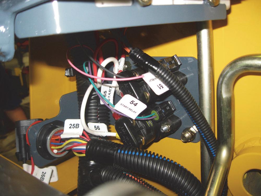
Electrical Chassis Components - DPF Models
Electrical Chassis Components - Non-DPF Models
NOTES:
1. COIL AND TIE BACKUP ALARM WIRES IN SAFE LOCATION WHEN NOT IN USE.
2. WIRE TIE ALTERNATOR WIRES TO THE STARTER. WIRES CANNOT CONTACT EXHAUST MANIFOLD OR MUFFLER.
3. APPLY HI-TACK GASKET ADHESIVE.
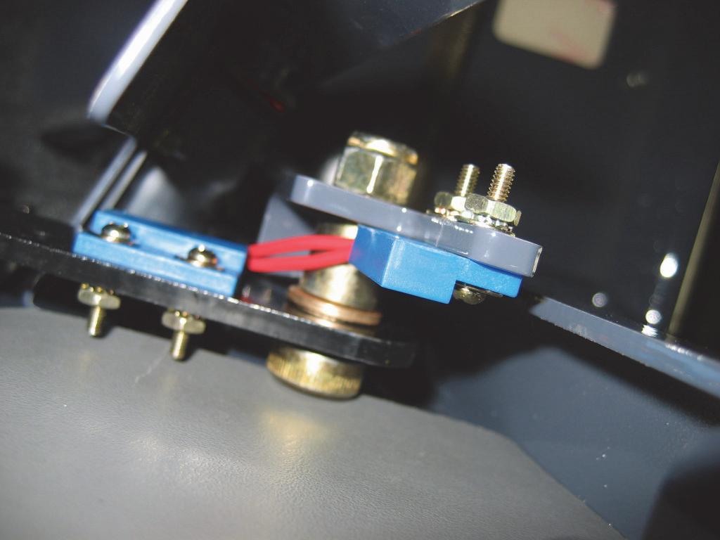
1STOP/BATTERY
12SENDER
13NUT/SPIRALOCK
14CLAMP/HOSE
15AUTO GLOW CONTROL
16SOLENOID
17RELAY MOUNTING BRKT ASSY
18COVER/ELECTRICAL
19NUT/FLRSUF
20RELAY MOUNT COVER ASSY
21RELAY/40 AMP/SEALED
Electrical ROPS/FOPS Components - DPF Models
1TIE/CABLE
2CLAMP/HOSE
3HLN INST
4CS FL LOCK
5NUT/SPEED
6HOUSING/DISPLAY 7BULB/LAMP
8GASKET. DISPLAY HOUSING
9CLAMP/HOSE
10GAUGE-FUEL LEVEL 11CONNECTOR,12V POWER PORT 12COVER,12V POWER PORT
Electrical ROPS/FOPS Components - Non-DPF Models
1TIE/CABLE
2CLAMP/HOSE
3HLN INST
4CS FL LOCK
5NUT/SPEED
6NUT/FLLSUF
7HLN INST
8GAUGE/HOURMETER
9HOUSING/DISPLAY
10BULB/LAMP
11GASKET. DISPLAY HOUSING
12CLAMP/HOSE
13GAUGE-TEMP (WATER)
14GAUGE-FUEL LEVEL
15CONNECTOR
16COVER,12V POWER PORT
17BREAKER/CIRCUIT 15 AMP
18BREAKER/CIRCUIT 25 AMP
19LIGHT SWITCH
20KNOB/CONTROL SKIRTED
21NUT/FLRSUF
22STANDOFF
23RELAY/40 AMP/SEALED
24SWITCH/IGNITION
25CIRCUIT BREAKER 8 AMPS
26MOUNT/WIRE
27SWITCH/BRAKE
29KNOB/CLAMPING
30COVER/ELECTRICAL
31PANEL/INSTRUMENT/ASSEMBLY
32DECAL/INSTRUMENT PANEL
33WIRE HARNESS/ROPS
34MOUNT/COVER ASSY 35LW
Power Distribution Module Test and Operation - DPF Models
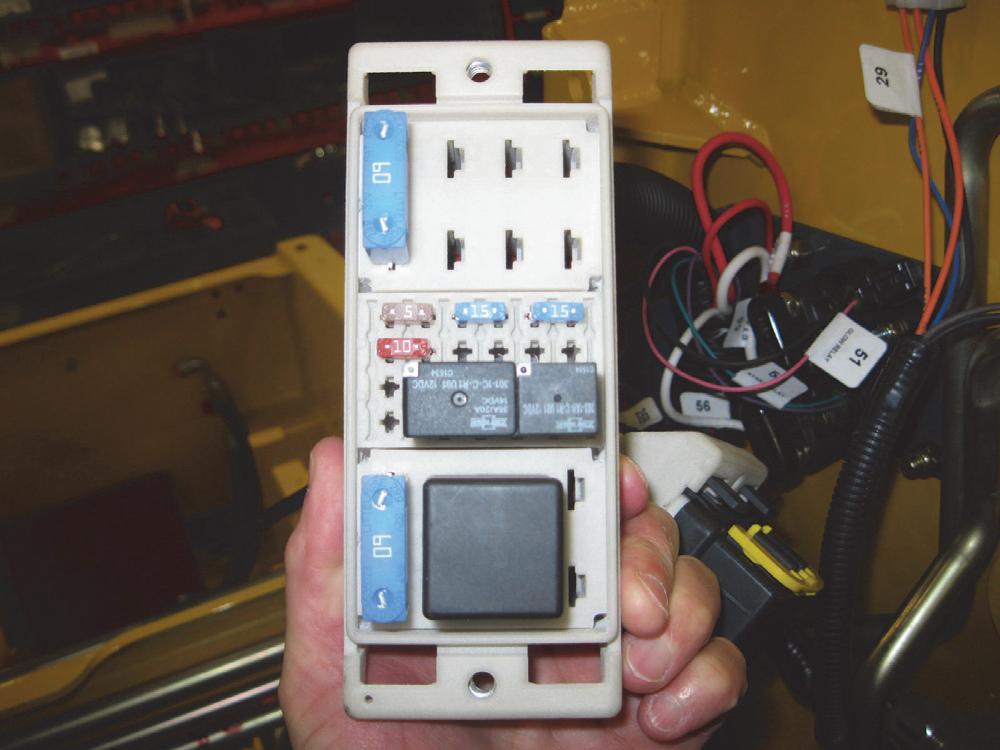
The electrical circuitry of Gehl R105 and Mustang 1050R DPF model skid-steer loaders are protected from overloading and short circuits by a combination of fuses and relays that are contained in the power distribution modules located in the engine and operator’s compartments. The Power Distribution Modules (PDM’s) in the engine compartment are positioned on the right side of the machine besides the fuel tank. These modules contain fuses and power relays that protect those circuits which utilize live power from the battery. The power relays function to provide keyswitched power to the circuits located in the forward PDM’s in the operator’s compartment. The outer surface of the cover of each PDM bears a decal that identifies the fuses and relays contained in that module.
Notes
Power Distribution Module Fuse Test

The following procedure can be used to test the fuses found inside the engine and ROPOS/FOPS PDM’s.
Warning
BEFORE beginning this service procedure, perform the following SAFETY procedure: ■ Shut off the engine.
(For detailed instructions, refer to the Safety chapter of this manual.)
1.The ROPS/FOPS PDM contains fuses for the instrument panel functions, headlights and safety interlock functions. A decal on the metal access cover identifies the fuses.

2. ROPS/FOPS Module: Fuses can be checked by removing them and inspecting the internal metal link. If the link is separated, replace the fuse.
4. Engine Modules: The PDM’s in the engine compartment contain fuses that protect the main power relays, engine operation circuits and rear lights.
3.Fuses may also be tested using a volt/ohm multimeter and checking for continuity between both fuse prongs.
5.Fuses can be checked by removing them and inspecting the internal metal link. If the link is separated, replace the fuse. Fuses may also be tested using a volt/ohm multimeter and checking for continuity between both fuse prongs.
6. Larger 60 amp fuses: Check for continuity between test points with the circuits turned “OFF”.
Power Distribution Module Relay Test
There are two power relays inside the engine compartment PDM’s that supply power to the fuses for individual circuits. The cover identifies the relays. There are several other relays in the ROPS/FOPS and engine compartment PDM’s that supply power for other circuits. The covers have a decal or is information is etched into the cover to identify the relays.

Machine Test: The relays can be tested in the machine as follows:
1.With an operator in the seat and the restraint bar lowered, turning the keyswitch to the “ON” position should produce an audible “click” from each relay closing.
2.While the keyswitch is in the “ON” position, test each relay individually, pull one relay out of the panel at a time, listening for the audible “click” of the relay opening.
3.Plug the relay back into the panel and listen for the audible “click” of the relay re-closing, if the circuit is activated.
4.Replace any relay for which there is no discernible “clicking” sound heard at keyed power or opening (removing) of the relay.
• The solenoid lock relay and start safety relay will actuate only with the keyswitch in the “ON” position, the restraint bar down and an assistant in the seat.
5.Replace any relay that does not have continuity between powered terminals #85 and #86.

Bench Test: The relays can also be tested on a work bench as follows:
Power Relays
1.A relay may be tested by removing it and taking it to a work bench. Apply a ground to terminal #85 and a 12 V source to terminal #86. The relay should actuate. There should be continuity between terminal #30 and terminal #87.
2.Replace any relay that does not have continuity between powered terminals.
Solenoid Test - Both DPF and Non-DPF Models
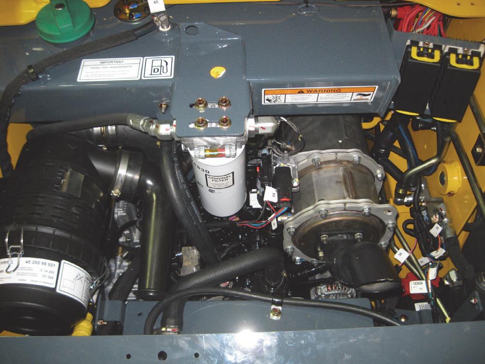
The following procedure can be used to test the engine starter and glow solenoids. They are located in the engine compartment on a panel on the right chassis riser. The bottom solenoid is used for the engine starter and the top solenoid is used for the engine glow circuit.
• With keyswitch in “OFF” position, there should be 12 VDC only on the top left large copper stud of each solenoid.
3.The top solenoid, the engine glow circuit will engage for a time, dependent on what the ambient temperature is. For DPF model loaders, the engine’s ECU provides the control current for the solenoid:
• With keyswitch in “OFF” position, there should be 12 VDC only on top left large copper stud of the solenoid.
• Unplug the control current connector and install a test lamp between #85 and #86 in the connector. Have a second operator turn the keyswitch to “ON” position, the test lamp should light if ambient temperature is low enough.
4.For the engine starter solenoid:
• With keyswitch in “OFF” position, there should be 12 VDC only on top left large copper stud of the solenoid.
• The external starter solenoid will engine when the keyswitch output calls for START.
• Unplug the control current connector and install a test lamp between #85 and #86 in the connector. Have an second operator turn the keyswitch to crank and the test lamp should light.
Warning
BEFORE beginning this service procedure, perform the following SAFETY procedure:
■ Shut off the engine.
■ Raise engine cover, lock open the rear grille. (For detailed instructions, refer to the Safety chapter of this manual.)
1.Remove two protective electrical covers from the solenoids.
2.Using a volt/ohm multimeter or test lamp, confirm the following condition with the wiring connected.
Relay Test and Operation - Non-DPF Models
Gehl R105 and Mustang 1050R Non-DPF model skidsteer loaders utilize relays in the electrical system to maximize the efficiency of engine, hydraulic, power and electrical operations. Following in this section are test and operation procedures.
Relay Test
The following procedure can be used to the test relays located behind a metal cover in the cab at the operator’s right elbow.

1.There should be 12-VDC on terminal #87 (#2 red wire from battery supply) at all times. Pushing horn button on left control handle should provide 12-VDC to terminal #86 and produce an audible “click” from relay. There should be 12-VDC on terminal #30 while horn button is pressed.
2. Relay coil test: Using a volt/ohm multimeter with all wires disconnected, measure the resistance across terminals #85 and #86. There should be 75 ohms ± 5 ohms. There should be no continuity between terminals #30 and #87.
Interlock Control Module Test
The following procedure can be used to test the interlock control module located inside the ROPS/ FOPS, behind the right metal access panel, near the operator’s right elbow.
Warning
BEFORE beginning this service procedure, perform the following SAFETY procedure:
■ Shut off the engine.
(For detailed instructions, refer to the Safety chapter of this manual.)
1.Remove two knobs securing the right metal access panel to the right ROPS/FOPS panel.
2.Put an operator in the seat with the restraint bar down.
3.Most module troubleshooting can be done by observing green diagnostic LED indicators.
• Disconnect 12-pin and 6-pin connectors and inspect terminals. Be sure no pins are bent on module and no sockets are damaged on harness. Replace damaged components and reconnect harness to control module.

4.Refer to truth table to analyze functionality of module. The module controls operation of components listed in OUTPUTS section of truth table. The ON or OFF state of various outputs is determined by ON or OFF state of various input conditions listed in INPUTS section of truth table. The keyswitch must be in “ON” position.
• Example 1 (initial keyswitch “ON”): At initial keyswitch ON, input LED “12-VDC In” should light and internal seat belt alarm should sound for five seconds.
5.The truth table section “Diagnostic LED States” specifies active (ON) state of each input and output.
• Example: Active (ON) state of engine oil pressure switch input (connector #1, pin #8) is a low or grounded input. Active state of seat switch input (connector #1, pin #3) is a high or 12VDC input.
1. BLUE - PARK BRAKE SOLENOID, (5 AMP MAX CONTINUOUS)
2. YELLOW - HYD RELAY, (3 AMP MAX CONTINUOUS)
3. BROWN - SEAT BELT LIGHT, (2 AMP MAX CONTINUOUS)
4. GREEN - PARK BRAKE LIGHT, (2 AMP MAX CONTINUOUS)
5. NOT USED
6. PINK - START RELAY, (3 AMP MAX CONTINUOUS)
MATING CONNECTOR: DEUTSCH PNB DT06-06S
INPUT PIN DESCRIPTIONS:
1. RED - KEYED POWER
2. BLACK - GROUND
3. WHITE - SEAT SWITCH
4. GREEN - RESTRAINT BAR SWITCH
5. PURPLE - PARK BRAKE SWITCH
6. GRAY - HYD TEMP SWITCH
7. ORANGE - ENG TEMP SWITCH
8. GRAY - IGN VOLT SENSE
9. WHITE - DOOR SWITCH
10. RED - CRANK SIGNAL
11. NOT USED
12. NOT USED
MATING CONNECTOR: DEUTSCH PNB DT06-12S
Seats - Standard and Suspension
Suspension Seat
Restraint Bar Components
Seat Switch Removal and Installation
Removal Procedure
Warning
BEFORE beginning this service procedure, perform the following SAFETY procedure:
■ Shut off the engine.
(For detailed instructions, refer to the Safety chapter of this manual.)
1.Remove seat per the procedure found in the Mainframe chapter. Turn the seat over.
2.Remove the two Phillips-head screws and nuts securing the seat switch to the seat. Press the three tabs to separate the dome from the base. Press the two tabs to remove the switch from the base.
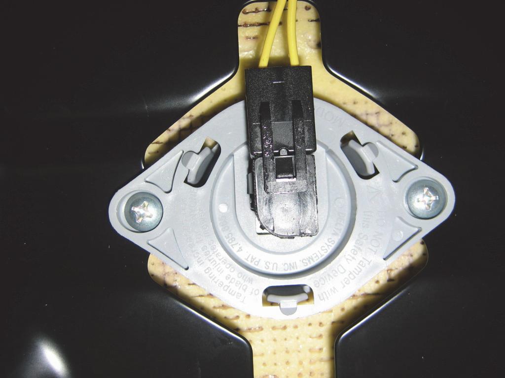
Restraint Bar Switch Removal and Installation
Removal Procedure
Warning
BEFORE beginning this service procedure, perform the following SAFETY procedure:
■ Shut off the engine.
(For detailed instructions, refer to the Safety chapter of this manual.)
1.Remove the restraint bar assembly per the procedure in the Mainframe chapter.
2.Remove the two machine screws, washers and hex nuts that secure the restraint bar switches to the restraint bar and restrain bar mount.
Warning
DO NOT attempt to operate the loader without the seat switch installed.
Installation Procedure - Follow all warnings first, then reverse the removal steps*.
* Install seat on loader per the procedure in the Mainframe chapter.
3.Remove the switches from the bracket assembly.
Warning
DO NOT attempt to operate loader without the restraint bar switch installed.
Installation Procedure - Follow all warnings first, then reverse the removal steps*.
* Adjust position of restraint bar switch and actuator switch so they are aligned with each other when restraint bar is down against the rubber stops.
* Install the restraint bar according to the procedure in the Mainframe chapter.
Electrical Lights Components
Front and Rear Work Light Bulb Replacement
Removal Procedure
Warning
BEFORE beginning this service procedure, perform the following SAFETY procedure:
■ Shut off the engine.
■ Raise engine cover; lock open the rear grille. (For detailed instructions, refer to the Safety chapter of this manual.)
Important
Halogen bulbs SHOULD NOT be touched with bare fingers; they can fail prematurely. Wear clean gloves or use a clean rag if you must handle the halogen bulbs.

4.Replace the used bulb with a new 55 W H3 bulb (if a white work light), or a new 35 W H3 bulb (for red warning light).


Installation Procedure - Follow all warnings first, then reverse the removal steps.

Dome Light Bulb Replacement Removal Procedure
Warning
BEFORE beginning this service procedure, perform the following SAFETY procedure:
■ Shut off the engine.
(For detailed instructions, refer to the Safety chapter of this manual.)
Diesel Particulate Filter (DPF) Regeneration Procedures - DPF Models
The Diesel Particulate Filter (DPF) treats exhaust emissions in compliance with Tier 4 / Stage 3B emission standards. The DPF filter relies on high exhaust temperatures. Periodic DPF maintenance (regeneration) is required, dependent upon machine operation load / temperature.
Note: Machines operated primarily at high loads and operating temperatures require less frequent DPF maintenance. Extended periods of engine idling rapidly increases DPF soot levels, requiring more frequent regeneration operations.

There are three modes of DPF regeneration:
• Passive / Assist Regeneration: Occurs automatically without operator input. Passive/assist regeneration does not affect machine operation.
• Reset Regeneration: Occurs automatically, but can be inhibited by the operator. Increases exhaust gas temperatures. Reset regeneration occurs approximately every 100 hours of operation.
Note: Reset regeneration effectiveness is improved if the machine is operated at mid- to high-throttle settings when reset regeneration mode is in progress.
• Stationary Regeneration: Requires operator action to initiate and takes approximately 25-30 minutes to complete.
Important: The machine cannot be operated and must be parked in a well-ventilated area away from flammable materials when stationary regeneration is in progress.
There is a possibility of carbon monoxide poisoning if stationary regeneration occurs in an enclosed space. Always perform stationary regeneration in a well-ventilated area.
During regeneration, there will be high exhaust gas temperatures, even at low load. Stay clear of the DPF during regeneration.
Reset Regeneration
Important: Reset regeneration can be prevented from occurring.
Reset regeneration occurs automatically (unless inhibited) approximately every 100 hours of operation.
Note: Reset regeneration effectiveness is improved if the machine is operated at mid- to high-throttle settings while regeneration is in progress.
When reset regeneration occurs, the DPF in-progress (elevated temperature) symbol (K) displays on the screen.
Stationary Regeneration
Stationary regeneration may be periodically required to reduce DPF soot build-up. The frequency of stationary regeneration is dependent upon machine operation and engine load.
The machine cannot be used during stationary regeneration and cannot be moved without interrupting the stationary regeneration process.
When stationary regeneration needs to be performed, the regeneration request screen displays on the information center electronic display.
Reset Regeneration Inhibit
DPF regeneration inhibit prevents reset regeneration from occurring.
Permanently inhibiting regeneration is not recommended, as this will eventually cause significant reduction in engine power and will force premature DPF soot filter replacement.
To temporarily inhibit reset regeneration, hold down button (U) until the strikethrough in the Reset Regeneration symbol (W) turns to red.
Note: The stationary regeneration request screen can be temporarily dismissed by pressing the reset regeneration inhibit button (U) for three seconds. Until the previous screen displays. The stationary regeneration request screen will return 1 minute after being dismissed, for as long as the request remains active.
Important: Perform stationary regeneration as soon as possible when the stationary regeneration request screen displays. Postponing stationary regeneration for extended periods will cause significant reduction in engine power and will force premature DPF filter core replacement.
To proceed with stationary regeneration:
1.Park the machine in a safe, well-ventilated location away from flammable materials.
2.The following conditions need to be met before stationary regeneration continues:
A.Press the button on the control keypad or lift the operator restraint bar to apply the parking brake. A checkmark is displayed next to the parking brake symbol (A).
Note: DPF in-progress (elevated temperature) symbol (K) will not be displayed when reset regeneration is inhibited.
B.When engine coolant has reached operating temperature (above 140° F / 60° C, a checkmark is displayed next to the coolant temperature symbol (B).
C.Place throttle controls to the lowest speed setting. A checkmark is displayed next to the engine RPM symbol when the engine is running at low idle.
Forcing Stationary Regeneration
Stationary regeneration can be performed at any time after 50 operating hours following the previous stationary regeneration.
To perform stationary regeneration on-demand: Press button (Y) associated with the DPF regeneration symbol (X), until the regeneration screen displays.
3.When all three checkmarks (A, B & C) are displayed on the Stationary Regeneration screen, press and hold the button (Z) until the Stationary Regeneration In-Progress screen displays.
DPF Maintenance
DPF soot filter replacement is required when the DPF (Diesel Particulate Filter) Service Screen displays.
Note: Stationary regeneration can be interrupted at any time by releasing the parking brake, advancing the throttle, or stopping the engine. Stationary regeneration must start again from the beginning if it is interrupted.
Stationary regeneration completion percentage is displayed as during the stationary regeneration progresses. Progress percentage disappears when stationary regeneration completes.
Note: Stationary regeneration takes approximately 2530 minutes.
Note: Contact your dealer when the DPF Service screen displays.
Caution
It is not necessary to stay in the machine during stationary regeneration. Keep the machine under observation while regeneration is in progress in case of malfunction. Keep bystanders away from the machine while regeneration is in progress.
Chassis Electrical Schematic - DPF Models (schematic overlaps onto following page)
Chassis Electrical Schematic - DPF Models
ROPS/FOPS Electrical Schematic - DPF Models (schematic overlaps onto following page)
Rops Harness
Rops Harness
ROPS/FOPS Electrical Schematic - DPF Models
Electrical Schematic - Non-DPF Models (schematic overlaps onto following page)
Electrical Schematic - Non-DPF Models
Chapter Notes
Introduction
This chapter covers troubleshooting, removal, installation, and adjustment procedures for engine components on Gehl R105 and Mustang 1050R model skid-steer loaders. The primary engine system components are shown on following pages. They are equipped with a Yanmar model 3TNV88CKMS (DPF Models) or a 3TNV88-BKMS (Non-DPF) naturally-aspirated diesel engine. Both are threecylinder engines with 100 cubic inch (1,64 L) displacement and a 18.5.1 compression ratio. The direct injection four-stroke engines have a firing order of 1, 3, 2.
A “full-flow” oil filter is used in the lubrication system. As with any engine, clean oil, fuel and air are critical to satisfactory performance and long engine life. If properly maintained, this engine can be expected to provide thousands of hours of trouble-free operation.
When ordering engine parts, always check the Gehl or Mustang Parts Manual to see if a special part has been fitted to the engine. If Gehl or Mustang parts are required, they can be ordered from Gehl Company.
Troubleshooting Guide
The following troubleshooting guide lists potential engine problems, as well as possible causes and remedies, for Gehl R105 and Mustang 1050R model skid-steer loaders.
When a problem occurs, don’t overlook simple causes. A malfunction could be caused by something as simple as an empty fuel tank. After a mechanical failure has been corrected, be sure to locate the cause of the problem. For further troubleshooting information, refer to the engine manufacturer’s manual.
Important
DO NOT attempt to service or repair major components, such as the fuel injector pump, unless authorized to do so by your Gehl or Mustang dealer. Any unauthorized repair will void the warranty.
Troubleshooting Guide
Starterwillnotengagewhenkeyswitch isturnedto“START”
Seatorrestraintbarswitch malfunctioningornotactivate
Batteryterminalsorcablesarelooseor corroded
Batterydischargedordefective
Startersolenoidinchassis malfunctioning
Ignitionwiring,seatswitch,restraint barswitch,etc.looseordisconnected
Starterorpinionfaulty
Replaceswitchesasneeded.
Cleanbatteryterminalsandcablesand tightenthem.
Rechargeorreplacebattery.
Troubleshootcircuitperwiringdiagram tolocatetrouble.Replacestarter solenoid.
Checkwiringforpoorconnections, brokenleads;repairwiringor connection.
Removestarter;repairorreplaceas needed.
Troubleshooting Guide
ProblemPossible CauseRemedy
Blown fuse.Check circuit and replace fuse. Dead battery.Charge or replace battery.
Battery disconnect switch in open position or malfunctioning.
Place battery disconnect switch into closed position— Repair or replace if necessary.
Starter malfunction.Repair/replace starter.
Operator not in operator’s seat.
Operator’s seat must be occupied for the engine to start.
Engine does not turn over
Malfunctioning seat/restraint bar/door switch/wiring.
Replace seat/restraint bar/door switch. Check wiring for poor connections, broken leads; repair wiring or connection.
Cab door open (if equipped).Close cab door.
Engine electronics logic error.Resolve error
Engine fault code(s) displayed.Identify problem and correct.
Relay malfunction.Replace relay.
Solenoid malfunction.
Troubleshoot circuit per wiring diagram. Replace solenoid as necessary.