
84 minute read
INTRODUCTION

With correct maintenance and proper use, the Gehl R105 and Mustang 1050R skid-steer loaders will give years of dependable service. This service manual is intended to be a guide in the assembly and disassembly, installation and removal, adjustment and testing, troubleshooting and replacement of components that together make up the Gehl R105 and Mustang 1050R skid-steer loaders.
In many of the procedures found within, the installation steps are the exact opposite of the removal steps and vice versa, and therefore, the opposite procedure is not written. Instead, a note to reverse the procedure will be stated. This reduces redundancy and excessive pages in the manual. In cases though, where the assembly and disassembly or removal and installation procedures differ and additional steps or safety concerns are paramount, the entire reverse procedure will be written out to include the new information.
The Table of Contents and Index can be used to make the procedure you need to find an easier process. Many schematics, photographs, and line art drawings are used to help perform the necessary repairs, tests, or adjustments that the skid-steer loader needs to keep it in good running condition.
If you have any additional questions, please contact your authorized Gehl or Mustang dealer or call the Manitou Americas Service Department for assistance.
Specifications
ModelR105 / 1050R
Engine MakeYanmar
Engine Model (DPF Models)3TNV88C-KMS
Engine Model (Non-DPF Models)3TNV88-BKMS
FuelDiesel
Displacement100 CID (1,64 L)
Horsepower - Net (DPF Models)35 hp (26 kW) @ 2800 rpm
Horsepower - Net (Non-DPF Models)35 hp (26 kW) @ 2600 rpm
Peak Torque (DPF Models)80 lbf-ft. (109 N•m) @ 1820 rpm
Peak Torque (Non-DPF Models)80 lbf-ft. (109 N•m) @ 1200 rpm
CapacitiesCapacities
Travel Speed (with standard tire)0 to 5.5 mph (0 to 9,0 km/h)
Tire OptionsTire Options Description
8.50 x 15 Heavy-Duty 8-PlyTitan
27 x 8.50-15 Heavy-Duty 8-PlyTitan
10.50 x 15 Heavy-Duty 8-PlyTitan
27 x 10.50 Heavy-Duty 8-PlyTitan
10 x 16.5 Heavy-duty 8-PlyTitan
7 x 15 SS NarrowTitan
Buckets and Capacities
Width - DescriptionCapacity (Heaped)
36 inches (914 mm) - Dirt/Construction5.3 cubic feet ; 0,15 cubic meters
44 inches (1118 mm) - Dirt/Construction7.4 cubic feet ; 0,21 cubic meters
48 inches (1219 mm) - Utility/Snow9.8 cubic feet ; 0,28 cubic meters
15.75-19.68-24 inches (400-500-610 mm) Pallet Not Applicable
*Operating capacity rated with a 8.50-15 tires, 10.3 cubic foot (0.3 m3) dirt/construction bucket in accordance with SAE J818, SAE J732 and ISO 14397-1.
Dimensional Specifications R105 / 1050R1 in.mm
AOverall operation height - fully raised1423607
BHeight to hinge pin - fully raised107.52731
COverall height - top of ROPS70.31786
DOverall length - bucket down1182997
EDump angle @ full height40º
FDump height822083
GDump reach - bucket (full height)25.25641
JRollback at ground31º
MRollback angle @ full height101º
OSeat-to-ground height32.5826
PWheelbase - nominal34.5876
QOverall width - less bucket48.5/571232/1448
ROverall bucket width55.31404
SGround clearance to chassis (between wheels)6.25159
VOverall length (less bucket)88.52248
WDeparture angle22º
XClearance circle - front (with bucket)721829
YClearance circle - front (less bucket)421067
ZClearance circle - rear541372
General Information
The above safety alert symbol means: ATTENTION! BECOME ALERT! YOUR SAFETY IS INVOLVED! It stresses an attitude of “safety awareness” and can be found throughout this service manual and on decals on the machine.

Before operating or working on this machine, read and study the following safety information. In addition, be sure that everyone who operates or works on this equipment is familiar with these safety precautions. It is essential to have competent and careful operators, who are not physically or mentally impaired, and who are thoroughly trained in the safe operation of the machine and the handling of loads. It is recommended that the operator be capable of obtaining a valid motor vehicle operator’s license.
The use of skid-steer loaders is subject to certain hazards that cannot be eliminated by mechanical means, but only by exercising intelligence, care and common sense. Such hazards include, but are not limited to, hillside operation, overloading, instability of the load, poor maintenance and using the equipment for a purpose for which it is not intended or designed.
Both Gehl and Mustang Company ALWAYS consider the operator’s safety when designing machinery and guards exposed moving parts for the operator’s protection. However, some areas cannot be guarded or shielded in order to assure proper operation. The Operator’s Manual and the decals on the machine warn of additional hazards and should be read and observed closely.
These topics in the Safety chapter of the service manual include procedures, which, when followed, will allow safe performance of service procedures: Mandatory Safety Shutdown Procedure, Lift Arm Support Device, Roll-Over Protective Structure (ROPS)/Falling Object Protective Structure (FOPS) Lock Mechanism, Loader Raising and Lowering Procedures, and Relieving Hydraulic Pressure.

Signal Words DANGER
“DANGER” indicates an imminently hazardous situation, which, if not avoided, will result in death or serious injury.
Warning
“WARNING” indicates a potentially hazardous situation, which, if not avoided, could result in death or serious injury.
Caution
“CAUTION” indicates a potentially hazardous situation, which, if not avoided, may result in minor or moderate injury. May also alert against unsafe practices.
Additional Safety Reminders
Read and understand the Service Manual and all decals before maintaining, adjusting or servicing this equipment.
Doors, Guards and Shields - Some photographs in this manual may show doors, guards and shields open or removed for illustrative purposes only. BE SURE all doors, guards and shields are in their proper operating positions before starting engine to operate unit.
Damaged or Worn-out Parts - For safe operation, replace damaged or worn-out parts with genuine Gehl/ Mustang service parts, before operating this equipment. Attachments - Gehl and Mustang loaders are designed and intended to be used only with Gehl/Mustang Company attachments or approved referral attachments. The Company cannot be responsible for operator safety if the loader is used with a non-approved attachment.
Battery Safety - To avoid injury from a spark or short circuit, disconnect the negative battery cable before servicing any part of the electrical system. Do not tip the battery more than 45º.
Loader Stability - A skid-steer loader’s stability is determined by its wheelbase and tread width. The following elements can affect stability: terrain, speed, load being carried or dumped, and sudden control movements. DISREGARDING ANY OF THESE FACTORS CAN CAUSE THE LOADER TO TIP, POSSIBLY RESULTING IN DEATH OR SERIOUS INJURY. Therefore, ALWAYS have the operator restraint bar lowered and wear the seat belt. Operate the controls only from the operator’s seat. Operate the controls smoothly and gradually at an appropriate engine speed that matches the operating conditions.
DO NOT exceed the rated operating capacity of the machine. For additional stability when operating on inclines or ramps, ALWAYS travel with the heavier end of the loader toward the top of the incline.
ALWAYS look to the rear before backing up.
When parking machine, before leaving seat, check restraint bar for proper operation. The restraint bar, when raised, applies the parking brake and deactivates lift/tilt controls and auxiliary hydraulics.
Operator visibility is limited in certain areas; ROPS/ FOPS posts, attachments, the lift arm, items in the cab, etc., can obstruct the operator's view and could mask hazards or people in the area around the machine. It is very important the operator is aware of these masked visibility areas before operating the machine, especially on busy worksites.
To reduce the hazards posed by masked visibility areas:
•Use caution when raising or lowering attachments; masked visibility areas can change dramatically when attachments and/or the lift arm is moved.
•Look around the machine before operating. Objects near the machine and close to the ground can be difficult to see from the operator’s position.
•Always look in the direction of travel, including reverse. A back-up alarm is not a substitute for looking behind you when operating the machine in reverse.
•Keep bystanders out of, and away from, the work area.
•Keep the lift arm as low as possible while traveling.
•Additional equipment may be installed on the machine to serve as visual aids (e.g., mirrors, CCTV systems) that provide visibility to areas masked by the machine structure. Keep all machine components that affect visibility in a clean, properly adjusted state and in good working order.
Static electricity can produce dangerous sparks at the fuel-filling nozzle. Do not wear polyester, or polyesterblend clothing while fueling. Before fueling, touch the metal surface of the machine away from the fuel fill to dissipate any built-up static electricity. Do not re-enter the machine but stay near the fuel filling point during refueling to minimize the build-up of static electricity. Do not use cell phones while fueling. Make sure the static line is connected from the machine to the fuel truck before fueling begins.
Ultra-Low Sulfur Diesel (ULSD) poses a greater static ignition hazard than earlier diesel formulations. Avoid death or serious injury from fire or explosion; consult with your fuel or fuel system supplier to ensure the entire fuel delivery system is in compliance with fueling standards for proper grounding and bonding practices. Exposure to crystalline silica (found in sand, soil and rocks) has been associated with silicosis, a debilitating and often fatal lung disease. A Hazard Review (Pub. No. 2002-129) by the U.S. National Institute for Occupational Safety and Health (NIOSH) indicates a significant risk of chronic silicosis for workers exposed to inhaled crystalline silica over a working lifetime. NIOSH recommends an exposure limit of 0.05 mg/m3 as a time-weighted average for up to a 10-hr. workday during a 40-hr. workweek. NIOSH also recommends substituting less hazardous materials when feasible, using respiratory protection and regular medical examinations for exposed workers.
Keyswitch - NEVER attempt to bypass the keyswitch to start the engine. Use the jump-starting procedure detailed in the Service chapter of the Operator’s Manual.
Hydraulic Fluid Leaks - NEVER use hands to search for hydraulic fluid leaks. Instead, use paper or cardboard. Fluid under pressure can be invisible, penetrate the skin and cause a serious injury. If any fluid is injected into skin, see a doctor at once. Injected fluid MUST be surgically removed by a doctor or gangrene may result.
Wear Safety Glasses - ALWAYS wear safety glasses with side shields when operating the machine or striking metal against metal. In addition, it is recommended that a softer (chip-resistant) material be used to cushion the blow. Failure to heed could lead to serious injury to eyes or other parts of the body.
ALWAYS wear safety glasses when searching for hydraulic leaks or when working near batteries.
Loaded Bucket/Fork - DO NOT raise or drop a loaded bucket or fork suddenly. Abrupt movements under load can cause serious loader instability.
NEVER push the lift control into the “float” position with the bucket or attachment loaded or raised, because this will cause the lift arm to lower rapidly.
DO NOT drive too close to an excavation or ditch. BE SURE that the surrounding ground has adequate strength to support the weight of the loader and the load.
DO NOT smoke or have any sparkproducing equipment in the area while filling the fuel tank or while working on the fuel or hydraulic systems.
Exhaust Gases - Exhaust fumes can kill. DO NOT operate this machine in an enclosed area unless there is adequate ventilation.
Engine - NEVER use ether or starting fluid.
People - NEVER carry riders. DO NOT allow others to ride on the machine or attachment, because they could fall or cause an accident.
BE SURE all persons are away from the machine and warn others in the area before starting the engine.
ALWAYS face the machine and use handholds and steps when getting on and off. DO NOT jump off machine.
Wear appropriate ear protection for prolonged exposure to excessive noise.
ALWAYS perform a daily inspection of the machine before using it. Look for damage, loose or missing parts, leaks, etc.
Remove trash and debris from the machine and engine compartment each day to minimize risk of fire.
New operators MUST operate loader in an open area away from bystanders. Practice with controls until the loader can be operated safely and efficiently.
Mandatory Safety Shutdown Procedure
BEFORE cleaning, adjusting, lubricating or servicing the unit or leaving it unattended:
1. Move drive control handle(s) to the neutral position.
2. Lower the lift arm and attachment completely. If the lift arm must be left in the “raised” position, BE SURE to properly engage the lift arm support device.
3. Move the throttle to the low idle position, shut off the engine and remove the key.
4. Before exiting, move the lift/tilt control(s) to verify that controls do not cause movement of the lift arm or hitch.
Only after these precautions can you be sure it is safe to proceed. Failure to follow the above procedure could lead to death or serious injury.
Lift Arm Support Device WARNING
BEFORE leaving operator’s compartment to work on the loader with the lift arm raised, ALWAYS engage the lift arm support device. Turn the keyswitch to OFF, remove the key and take it with you.
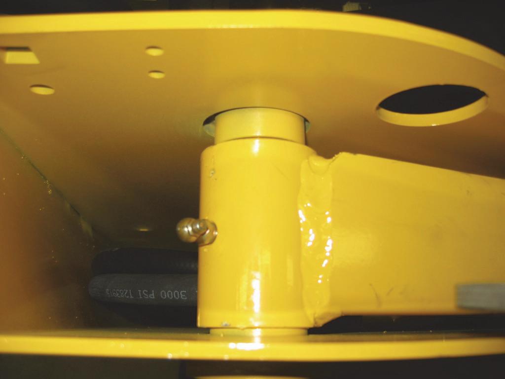
Many service procedures require a raised lift arm to allow easier access to loader components. For operator and service personnel safety, a lift arm support device is standard on Gehl and Mustang skid-steer loaders. Used as a cylinder block, it helps prevent a raised lift arm from unexpectedly lowering.
BE SURE to engage the lift arm support device whenever the lift arm is raised. When the device is not being used, secure it to the anchor on the underside of the lift arm using the slide latch and retainer provided.

The lift arm support device is a safety device which must be kept in proper operating condition at all times. The following procedures outline the correct way to engage and disengage the lift arm support device.
Lift Arm Support Device Engagement
1.Remove any attachment from the lift arm.
2.Lower the lift arm until contact with the loader frame.
3.Turn keyswitch to OFF position to stop engine.
4.Leave the operator’s compartment. Pull down on the lock pin button to release its locking mechanism. Pull out the lock pin holding the support device up against the lift arm. All the support device to come down into contact with the lift cylinder.
5.Return to the operator’s compartment and restart the engine.
6.Use the lift control to raise the lift arm until the lift arm support device drops over the end of the lift cylinder and around the lift cylinder rod. Slowly lower the lift arm until the free end of the support device contacts the top (rod end) of the lift cylinder.
Lift Arm Support Device Disengagement
Warning
NEVER leave the operator’s compartment to disengage the lift arm support device with the engine running.
To return the lift arm support device to its storage position, proceed as follows:
1.Raise the lift arm completely.
2.Turn the keyswitch to the OFF position to stop the engine, remove the key and take it with you.
Warning
BEFORE testing the machine, ALWAYS clear people from the area.
3.Before leaving the operator’s compartment, check to be sure the lift arm is being held in the raised position by the solenoid valve (See NOTE).
NOTE: With the keyswitch OFF, and the solenoid valve functioning properly, the lift arm will not move when the lift control is moved forward. If the valve does not hold the lift arm, DO NOT leave the operator’s compartment. Instead, have someone store the support device for you. Then, contact your Gehl/Mustang dealer to determine the reason why the lift arm lowers while the keyswitch is in the OFF position.

4.To store the lift arm support device, remove it from the lift cylinder rod and return it to its storage location. Secure the support device under the lift arm with the lock pin.
ROPS – Raising
For service, the ROPS can be unbolted and tilted back. Gas-charged springs help tilt it back. A self-actuating lock mechanism engages to lock the ROPS in a rolledback position.
1.The lift arm should be lowered or locked in the raised position as per the “Lift Arm Support Device Engagement” procedure in this chapter.
2.Turn the keyswitch to the OFF position to stop the engine. Remove the key and take it with you.
3.Leave the operator’s compartment.
Warning
DO NOT leave the operator’s compartment with the engine running. Before leaving the loader, shut off the engine according to the “Mandatory Safety Shutdown Procedure” described in this chapter.
4.Remove one capscrew, three washers and one nut and mounting isolator on each side of the ROPS forward stanchions
5.Lift ROPS up and tilt it back until the self-actuating lock mechanism engages. The lock mechanism locks the ROPS in a rolled-back position.
2.Lower the ROPS until it contacts the chassis.
Important
BEFORE raising the ROPS, position the seat as far back as it will go. Avoid damaging control handles by slowly raising the ROPS. BE SURE the control handles clear the ROPS.

ROPS – Lowering
1.With an assistant’s help, apply upward force on the ROPS while pulling the lock mechanism handle toward the front of the loader.

Important
Avoid damaging control handles by slowly lowering the ROPS. BE SURE the control handles clear the ROPS.

3.Be sure control handles clear the ROPS.
4.Reinstall the one capscrew, three washers and one nut and mounting isolator on each side of the ROPS forward stanchions.
Relieving Hydraulic Pressure
The following procedure should be used to relieve pressure in the hydraulic system before performing service procedures on hydraulic system components.
1.Completely lower the bucket or attachment.
2.Turn the keyswitch to the “OFF” position to shut off engine.
3.With the operator in the seat and the restraint bar lowered, turn the keyswitch to the “ON” position, but DO NOT start the engine.
4.Move the lift, tilt and auxiliary hydraulics controls through several cycles.
Loader Raising Procedure
The following procedure is used to raise the skid-steer loader so that all four tires are off the ground.
Warning
BEFORE servicing the machine, exercise the “Mandatory Safety Shutdown Procedure” described in this chapter.
Warning
DO NOT rely on a jack or hoist to maintain the “raised” position without additional blocking and supports. Serious personal injury could result from improperly raising or blocking the skid-steer loader.
1.To raise and block the skid-steer loader, obtain four jack stands (or blocks) of sufficient strength to support the loader. A reinforced pallet may also be used.
2.Using a jack or hoist capable of raising the fullyequipped loader, lift the loader until the tires are off the ground.
3.Place the reinforced pallet, jack stands (or blocks) under the flat part of the loader chassis. Place them parallel with, but not touching, the tires.

4.Slowly lower the loader so that its weight rests on the reinforced pallet, jack stands (or blocks).
5.When the procedure is finished, all four tires will be off the ground, and the wheels can be removed as necessary.
Loader Lowering Procedure
When the service procedures are complete, the skidsteer loader can be taken down from the “raised” position. To lower the loader onto its tires:
1.Using a jack or hoist, raise the loader until its weight no longer rests on the reinforced pallet, jack stands (or blocks).
2.Carefully remove the reinforced pallet, jack stands (or blocks) under the loader.
3.Slowly lower the loader until the tires are on the ground.
Notes
General Information WARNING
NEVER service this unit when any part of the machine is in motion. ALWAYS BE SURE to exercise the “Mandatory Safety Shutdown Procedure” (see Safety chapter) BEFORE servicing this equipment.
Routine lubrication is an important factor in preventing excessive part wear and premature failures. Loader and engine operation depend on using correct grade, highquality lubricating oils. This chapter and the chart below list locations, temperature ranges and types of recommended lubricants to be used when servicing this machine. In addition, refer to the engine manual for specific grades and ratings as specified by the engine manufacturer.
Important
Whenever service is performed on hydraulic components (valves, cylinders, hoses, etc.), fuel tanks and lines, care must be taken to prevent discharging fluid onto the ground. Catch and dispose of fluid per local waste disposal regulations.

Hydraulic Oil Reservoir
The oil reservoir for hydraulic and hydrostatic systems has a capacity of 8.0 U.S. gallons (30 liters). A dipstick built into the reservoir cap provides a visual oil level indicator for convenient maintenance of the hydraulic oil level.
The hydraulic oil reservoir should be drained and filled after every 500 hours of operation or annually (whichever occurs first).
Hydraulic System Reservoir
Use Petro-Canada Premium HVI60, or equivalent that contains anti-rust, anti-foam, and anti-oxidation additives and conforms to ISO VG46.
Capacity: 8.0 Gallons (30 L)
ChaincasesGrease FittingsCrankcase Oil
Use hydraulic system oil or SAE grade 15W-40 motor oil.
Capacity (each side): 8.0 Quarts (7,6 L)
Use lithium-based greaseBelow 32°F (0°C) use SAE Grade* 10 or 10W-30
Above 32°F (0°C) use SAE Grade* 15W-40
*Service Classification: API - CJ-4 SM
Capacity (w/ filter change): 7.6 Quarts (7,2 L)
Use Petro-Canada Premium HVI60 hydraulic oil (or ISO VG46 equivalent) that contains anti-rust, anti-foam and anti-oxidation additives. Hydraulic oil filter element should be replaced after every 500 hours of operation or annually (whichever occurs first). For details, refer to “Hydraulic Oil Filter Element Replacement” procedure in the Hydraulics System chapter.
NOTE: An initial 50-hour hydraulic oil filter element replacement is recommended for new skid-steer loaders.
Hydraulic Oil Tank Drain Procedure
1.Open the engine access cover and lock open the rear grille.
2.Because the tank is pressurized, slowly remove the hydraulic oil tank cap from the filler neck.
3.Underneath the left riser, remove the drain plug on the hydraulic oil tank. Place a suitable container under the drain plug hole to catch the hydraulic oil.
NOTE: Care must be taken to prevent discharging fluid onto the ground. Catch and dispose of fluid per the local waste disposal regulations.
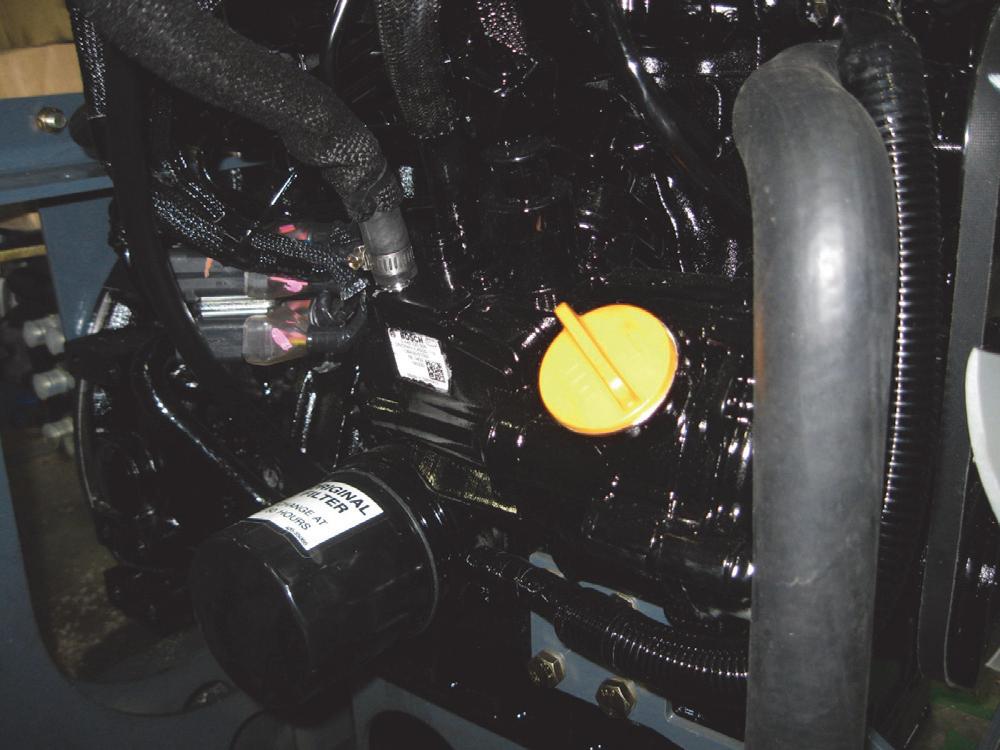
Crankcase Oil
The Yanmar three-cylinder diesel engine crankcase has a capacity of 7.6 U.S. quarts (7,2 liters). The chart below lists recommended oil viscosity for the Yanmar engine.
Below 32°F (0°C)SAE 10 or 10W-30
Above 32°F (0°C)SAE 15W-40
Service classification: API - CJ-4 SM
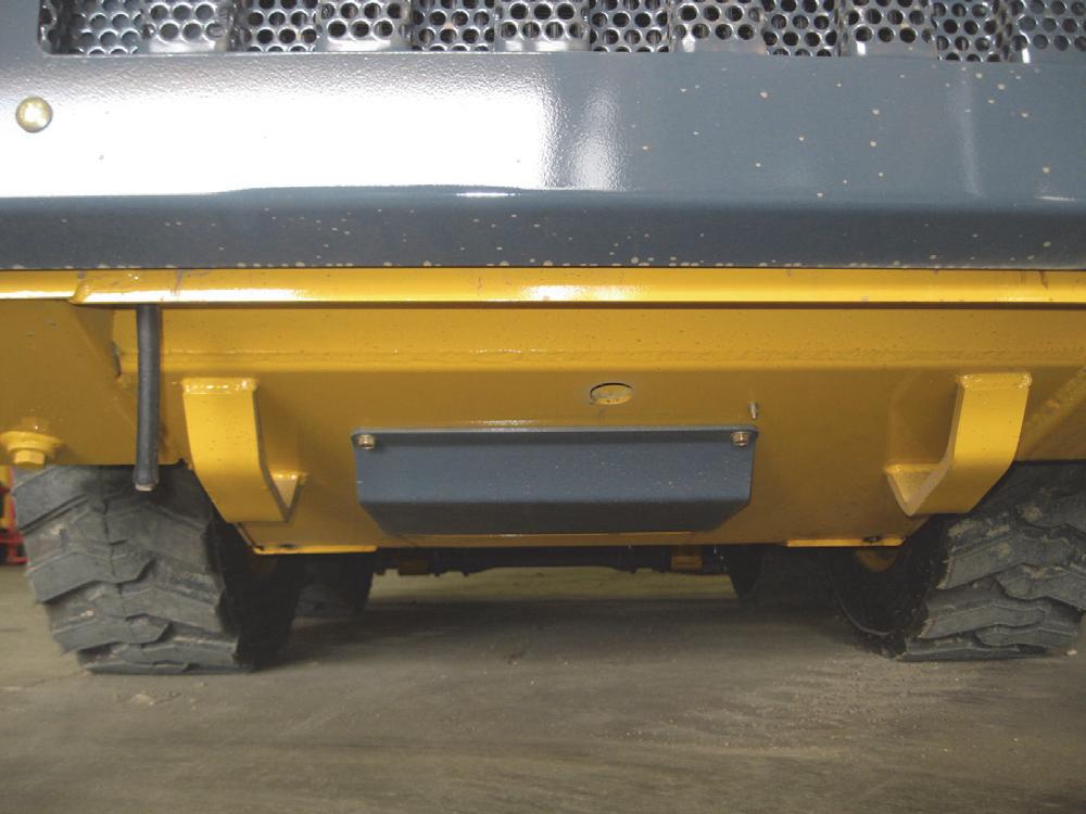
Engine oil should be changed and filter element replaced every 500 hours of service. Access to the engine oil filter and drain plug is from underneath the skid-steer, through the rear belly pan.

Refer to engine operator’s manual (see NOTE) for details on changing oil, and to “Oil Filter Removal” and “Oil Filter Installation” procedures in Engine chapter of this manual.
NOTE: Refer to engine operator’s manual for additional information on oil change intervals, including the 50-hour initial oil change.
Chaincases
Each chaincase requires 8.0 U.S. quarts (7,6 L) of motor oil. This quantity of oil should be maintained at all times. The oil in both chaincases should be drained and refilled every 1000 hours of operation or annually, whichever occurs first.
NOTE: An initial 50-hour chaincase oil change is recommended for new skid-steer loaders.

Change Chaincase Oil
1.Find a level position outdoors or in a workshop.
2.Remove drain plug on either chaincase and drain the oil into a suitable container.
Important
Always dispose of waste lubricating oil according to local regulations or take to a recycling center for disposal; do not pour onto the ground or down the drain.
3.Reinstall the chaincase drain plug.
4.Remove the chaincase oil fill plug.
5.Add motor oil through the chaincase fill/check plug until oil begins to flow out of the fill/check plug.
6.Reinstall the fill/check plug.
Grease Fitting Locations
Use lithium-based grease on all grease fittings. Grease every 10 hours of operation (or daily)
1.Grease All-Tach® hitch attachment pivots.

Cooling System Drain Procedure
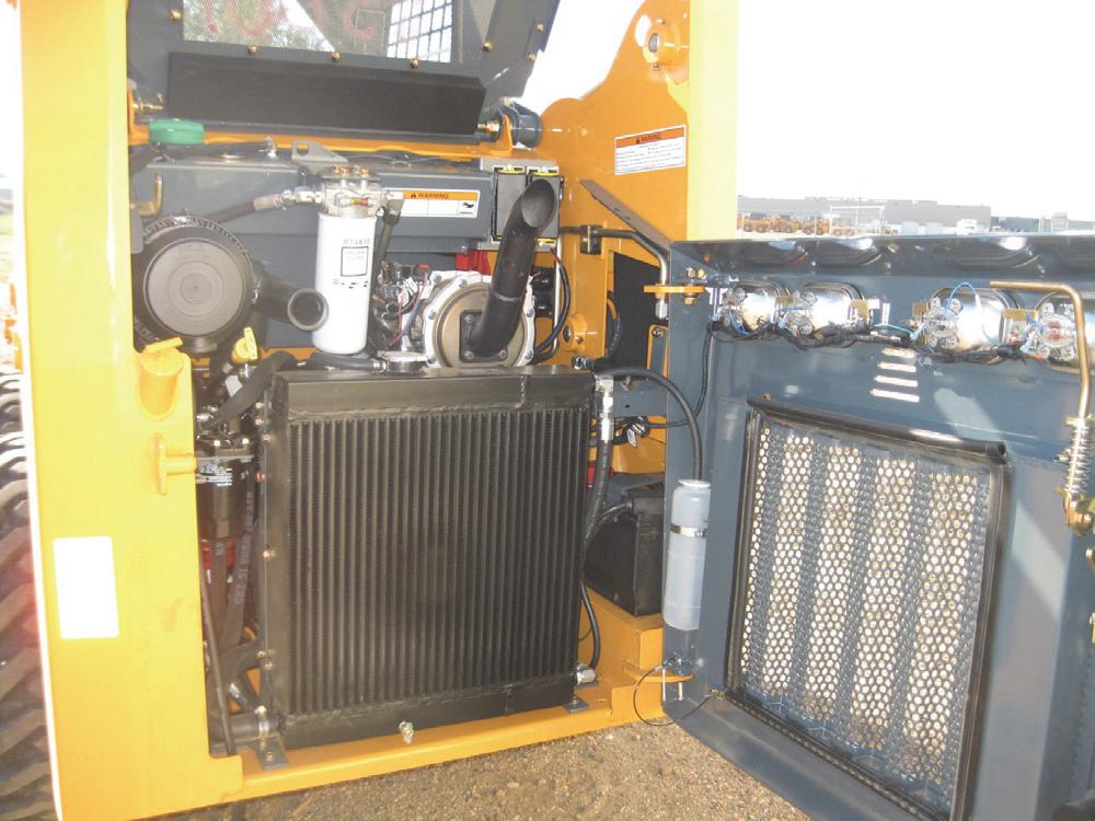
Gehl R105 and Mustang 1050R kid-steer loaders use a hydraulic oil cooler/radiator design to help keep the hydraulic oil and engine coolant from overheating. Many procedures in this Service Manual require partially or fully draining the radiator/cooler to perform the procedures.

Warning
BEFORE beginning this service procedure, perform the following SAFETY procedure:
■ Shut off the engine and allow it to cool.
(For detailed instructions, refer to the Safety chapter of this manual.)
Radiator Drain Procedure
1.Open the engine access cover and lock open the rear grille.
2.Remove the radiator cap.
3.A drain cock is located at the bottom rear of the radiator.
4.Place a catch pan with a capacity of at least 10-gallons (37,9 L) behind and underneath the chassis, below the drain cock or plug.

5.Open the drain cock and drain the coolant into a suitable container.
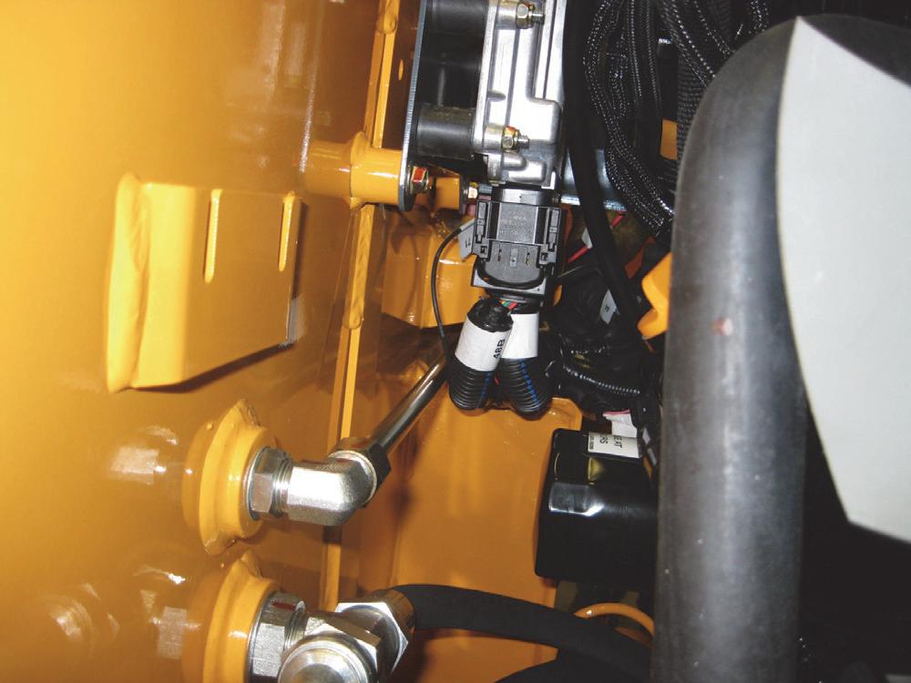
2.On the cooler side, unscrew the bottom right cooler hose from the 90º fitting in the cooler port and plug/cap the hose and the 90º fitting.
NOTE: Care must be taken to prevent discharging fluid onto the ground. Catch and dispose of fluid per the local waste disposal regulations.
6.Close the drain cock when finished draining.
7.Refill the radiator per the specifications found in the Specifications chapter.
Hydraulic Oil Cooler Plug/Cap Procedure
1.On the oil cooler side, unscrew the 90º fitting from the top right cooler hose and plug/cap the hose and the 90º fitting.
Note: Plugging or capping the two hoses in steps 1 and 2 will help prevent hydraulic oil from spilling onto the floor of the chassis if removal of the radiator/cooler is required.

Chapter Notes
Introduction
Gehl R105 and Mustang 1050R model skid-steer loaders have a welded steel chassis. Maintenance, service and repair may be performed through standard access panels.
Two side chaincases provide mounting for the drive motors and for the front and rear axles. The side cases also serve as sealed housings for the drive chains and sprockets. Oil is used inside these cases to ensure the chains always receive proper lubrication.
The lift arm and the lift and tilt cylinders are mounted with pivot pins. Capscrews are used to secure the pivot pins. A Rollover Protective Structure/Falling Object Protective Structure (ROPS/FOPS) is standard for operator safety, and both the seat and restraint bar include interlock switches.
1TIE/CABLE
2CLAMP/HOSE
3NUT/FLLSUF
4LOCKNUT
5FUEL SENDER GASKET
6CAP ASSEMBLY-FILLER
7SENDER
8PLUG 9PLUG 10FILTER/VENT
11COVER/AXLE ACCESS
12COVER/CHAINCASE ACCESS
13COVER OIL PAN
14DOWN STOP
15VENT/REMOTE
16PLATE/VALVE MOUNT
17KICK PLATE
18THWH TR
19LN FL SERR
20LN FL SERR
21CAP/FUEL FILLER
22STRAINER/FUEL
23CS FLAT HD
24COVER
25SHIM
26HOSE /FUEL
27FITTING/STRAIGHT
28CHASSIS
29PLATE/COVER
30FUEL
31PLATE/FUEL SEPARATOR
32FITTING/90
33PAN/BELLY
34FITTING/90
35BOLT/CARRIAGE
36BOLT/CARRIAGE
37BOLT/CARRIAGE
38BOLT/CARRIAGE
39SCREW/CAP
40THWH TC USL
41HWHMS
42HWHTRS TAP/R
43SCREW/CAP
Mainframe (Chassis) - Non-DPF Models
1TIE/CABLE
2CLAMP/HOSE
3NUT/FLLSUF
4LOCKNUT
5FUEL SENDER GASKET
6CAP ASSEMBLY-FILLER
7SENDER
8PLUG 9PLUG 10FILTER/ VENT
11COVER/AXLE ACCESS
12COVER/CHAINCASE ACCESS
13FUEL TANK
14COVER OIL PAN
15DOWN STOP
16VENT/REMOTE
17PLATE/VALVE MOUNT
18KICK PLATE
19THWH TR
20NUT/FLRSUF
21CS FLAT HD
22COVER
23SHIM 24HOSE /FUEL
25CHASSIS
26PAN/BELLY
27BOLT/CARRIAGE
28BOLT/CARRIAGE
29BOLT/CARRIAGE
30THWH TC USL
31HWHMS
32HWHTRS TAP/R
33HN
Engine Access Cover - Removal and Installation
Warning
BEFORE beginning this service procedure, perform the following SAFETY procedure:

■ Shut off the engine.
(For detailed instructions, refer to the Safety chapter of this manual.)
Removal Procedure
1.Open the engine access cover and lock open the rear grille.
2.Disconnect the gas spring from the engine access cover by removing the gas spring clip at the access cover end of the gas spring, and then pulling the gas spring off the ball stud on the access cover.
Installation Procedure - Follow all warnings first, then reverse the removal steps.

Roll-Over and Falling Object Protective Structure Components - ROPS/FOPS
1SCREW/SHOULDER
2SCREW/SHOULDER
3SCREW/SHOULDER
4BUSHING/OILITE
5WASHER/FLAT
6MOUNTING/ISOLATOR
7NUT/SPEED
8HLN INST
9LN LG FL SERR
10LOCKNUT
11LOCKNUT
12LOCKNUT
13ISOLATOR/ROPS
14ROPS SUPPORT
15ROPS LATCH
16PLATE/UPRIGHT SUPPORT
17BUSHING
18TAG/RIP CORD
19RING
20GAS SPRING/ROPS
21LN FL CTR
22ROPS/FOPS
23PHIL PAN S
24INSTRUMENT PANEL/LEFT
25PLATE/HEATER SEAL
26COVER/SEATPLATE
27SPRING/EXTENSION
28WASHER/FLAT PLATED
29STRIP/LOCKING
30REAR
33TOP WINDOW
34SHIELD/ASSEMBLY
35FOAM, REAR PANEL/ROPS
36FOAM, SIDE RH/ROPS
37FOAM, SIDE RH/ROPS
38FOAM, SIDE LH/ROPS
39FOAM, SIDE LH/ROPS
40FOAM, HEADLINER/ROPS
41HWHMS
ROPS/FOPS Removal and Installation WARNING
BEFORE beginning this service procedure, perform the following SAFETY procedure:
■ Shut off the engine.
(For detailed instructions, refer to the Safety chapter of this manual.)
Removal Procedure
1.Remove the engine access cover per the procedure in this chapter.
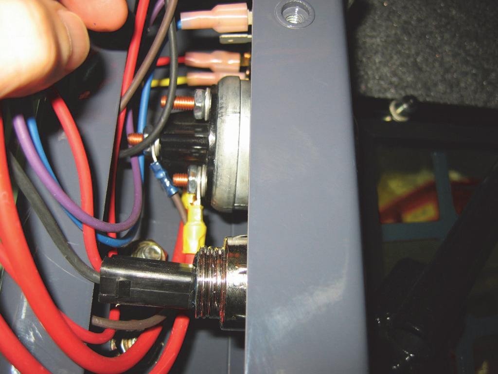
2.Disconnect the negative (-) battery cable at the battery, or, if equipped, turn the electrical disconnect switch to OFF.
3.Disconnect ROPS/FOPS harness connectors at the harness bulkhead, right of the fuel tank.
6.If equipped with a cab heater, remove the three clamps securing the heater hoses to the left side of the ROPS/FOPS.


4.Raise the ROPS/FOPS per the procedure in the Safety chapter of this manual.
5.With the ROPS/FOPS rolled back and locked, attach a suitable hoist of adequate capacity and a positive locking mechanism able to support the ROPS/FOPS or equivalent to the ROPS/FOPS.
Warning
The hoist MUST BE situated precisely above the ROPS/FOPS or else performing the following steps may cause the ROPS to swing as the bolts are removed. This could cause serious bodily injury and/or damage the loader.
7.Remove one capscrew and flat washer securing each gas spring to the ROPS/FOPS.
8.Disconnect the ROPS/FOPS lock mechanism from the welded hinge by removing the shoulder bolt and locknut. Remove the limiter assembly from the ROPS/FOPS.
9.The hardware connecting the ROPS/FOPS to the chassis should already be removed per the engine access cover removal procedure in this chapter.

10.Lift the ROPS/FOPS off the loader.
Seat Removal and Installation WARNING
BEFORE beginning this service procedure, perform the following SAFETY procedures:
■ Remove attachment from lift arm.
■ Raise lift arm; engage lift arm support device.
■ Shut off the engine.
■ Tilt back ROPS/FOPS until lock engages. (For detailed instructions, refer to the Safety chapter of this manual.)

Removal Procedure
Installation Procedure - Follow all warnings first, then reverse the removal steps.
1.Remove four nuts from the studs attaching the seat to the seat pan underneath the ROPS/FOPS.
2.Release the lock mechanism and lower the ROPS/ FOPS.
3.Disconnect seat switch from the wiring harness.

4.Lift the seat from the seat pan.
Installation Procedure - Follow all warnings first, then reverse the removal steps.

Seat Slide Replacement
Replacement Procedure
1.Remove the seat per the procedure in this chapter.
2.Remove the four screws attaching the seat slides to the seat.
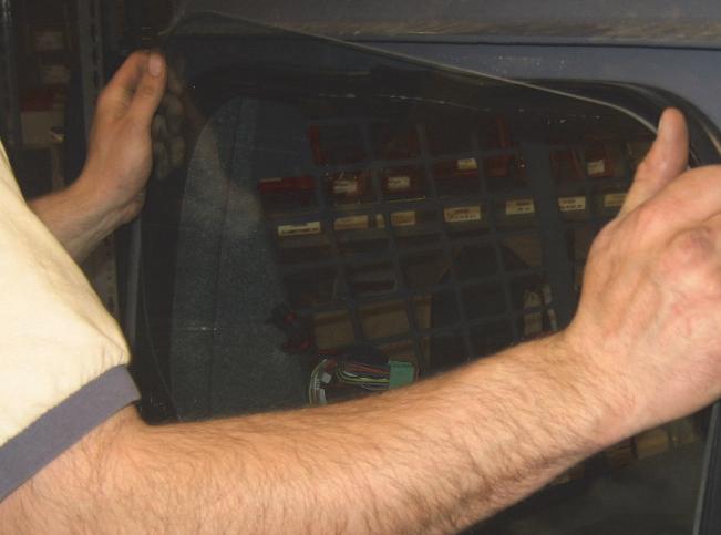
ROPS/FOPS Rear Window Removal and Installation
Warning
BEFORE beginning this service procedure, perform the following SAFETY procedure:
■ Shut off the engine.
(For detailed instructions, refer to the Safety chapter of this manual.)
Removal Procedure
1.Grab and pull emergency exit tag until the ripcord pulls free of rubber seal.
3.Slowly pull weatherstrip away from window frame.
5.Use L-hook tool between glass and weatherstrip and work it underneath the glass. Lift the glass lip up over the weatherstrip.
Installation Procedure
1.Recommended but not required: Mix a solution of 10% liquid dish soap and 90% water in a spray bottle.
NOTE: To install the rear window, obtain two insert tools from your glass dealer.

6.Use the pigtail hook tool to “pull down” weatherstrip seal on the outside of the ROPS/FOPS to secure the window.

2.Apply soap solution to window, weatherstrip and metal frame surfaces.
3.Start at top of window frame and install weatherstrip with the ripcord lip facing inside the ROPS/ FOPS and the glass lip facing out.
4.From inside the ROPS/FOPS, spray soap solution between glass window and inside edge of rear window.


7.On the inside of the ROPS/FOPS, install the ripcord in the ripcord lip, starting at top of weatherstrip. Be sure to have emergency exit tag slipped over the ripcord before performing this step.
8.Using L-hook tool, secure the ripcord in the ripcord lip by “pulling down” the lip over the cord.
9.Test the window for security and mating of all seals.
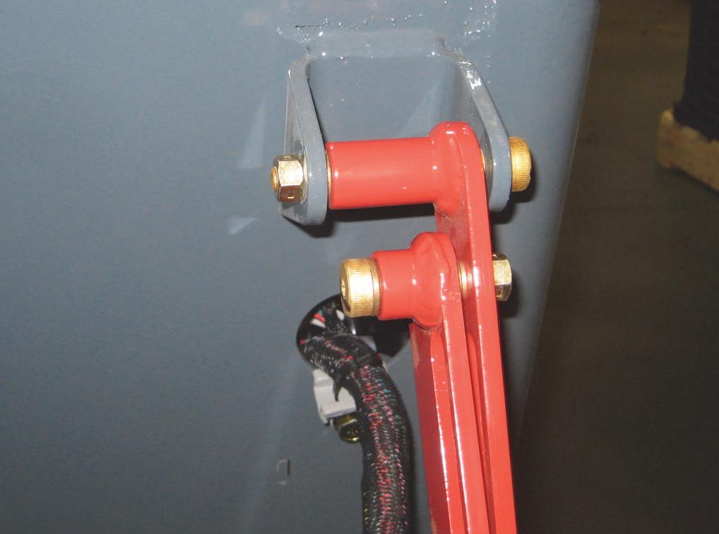
Restraint Bar Components
Restraint Bar Removal and Installation
Removal Procedure
1.Pop four “Christmas tree” clips off each restraint bar hinge cover. Pull the cover over the shoulder bolt and down the arm of the restraint bar to the rubber arm rest.

3.Remove one shoulder bolt, washer and locknut securing each side of the restraint bar to the ROPS/ FOPS. Remove the restraint bar.
NOTE: For restraint bar switch removal, refer to the Electrical chapter.
Installation Procedure - Reverse the removal steps.
2.Unplug the restraint bar switch red wire from the ROPS/FOPS wire harness.

Lift Arm Components - Gehl
1BUSHING/OILITE
2BUSHING/OILITE 3NUT/LOCK
4PIN/KLIK
5LIFTARM
6PIN/LIFTARM
7SUPPORT/STEP
8NUT/CENTERLOCK
9PIN/PIVOT
10STOP/LIFTARM LEFT
11STOP/LIFTARM RIGHT
12ROD/WIPER
13STOP/RUBBER
Lift Arm Components - Mustang
All-Tach® Hitch Components
NOTE:
1. APPLY LOCK TIGHT 242 TO ITEMS 10, 17, AND 18.
2. SPRING PIN TO EXTEND EQUAL DISTANCE ON EACH SIDE OF ADAPTOR ROD, BUT NOT BEYOND FACE PLATE OF WELDMENT.
3HANDLE/ATTACHMENT BRACKET LEFT 4HANDLE/ATTACHMENT BRACKET RIGHT
HEAD
All-Tach® Hitch Removal and Installation
Removal Procedure
1.Lower the lift arm and slightly extend the two tilt cylinders.
NOTE: Attach a suitable hoist of adequate capacity and a positive locking mechanism able to support the hitch or equivalent before performing the next step.
2.Remove two capscrews and locknuts securing the lower tilt cylinder pivot pins. While supporting the tilt cylinders, drive the pins out of their mounts.
Lift Arm Removal and Installation
Removal Procedure
1.Lower the lift arm.
2.Remove the bucket or attachment from the loader.
3.Remove the hitch per the procedure in this chapter.
Warning
BEFORE continuing this service procedure, perform the following SAFETY procedures:
■ Shut off the engine.
■ Relieve hydraulic system pressure.
(For detailed instructions, refer to the Safety chapter of this manual.)
4.Attach a suitable hoist of adequate capacity and a positive locking mechanism able to support the lift arm or equivalent to the lift arm assembly.
5.Remove two locknuts and capscrews securing the lift cylinder pivot pins to the lift arm.
3.Remove two capscrews and locknuts securing the hitch to the lowest pivot pins on the lift arm, and drive the pins out of their mounts.
Warning
ALWAYS wear safety glasses with side shields when operating the machine or striking metal against metal. In addition, it is recommended that a softer (chip-resistant) material be used to cushion the blow. Failure to heed could lead to serious injury to eyes or other parts of the body.
Installation Procedure - Reverse the removal steps.
6.While supporting the lift cylinder, remove the lift cylinder pins from the lift arm. Left side lift cylinder: Remove the lift arm support device secured to the lift arm by the lift cylinder pin and lynch pin. Keep lynch pin in a safe place.

7.Repeat steps 5 and 6 for other side of the lift arm.
NOTE: Always clean around hydraulic fittings before disconnecting any hydraulic line. When removing hydraulic lines, cap or plug the ends to prevent contaminating the hydraulic system.
NOTE: To help in the correct reassembly of the hydraulic hoses and tubes, mark them prior to disassembly with an oil-resistant chalk or marker or other suitable marking material.
8.Disconnect four upper and lower tilt cylinder hoses from the tilt cylinder.
11.Remove capscrews, line clips, hose guide and tee fittings from the tilt hoses secured underneath the lift arm and on its crossmember. Remove tilt hoses.
9.Remove both tilt cylinders from the lift arm per the procedure in the Hydraulics System chapter.


10.Remove four self-tapping screws securing the support step to the hydraulic tubes cover plate and remove the plate.


12.Disconnect two hydraulic tubes from their 90° fittings on two flat-faced quick couplers located on the left knee of the lift arm.
13.Remove three self-tapping screws securing the auxiliary bracket to the lift arm at the quick couplers.
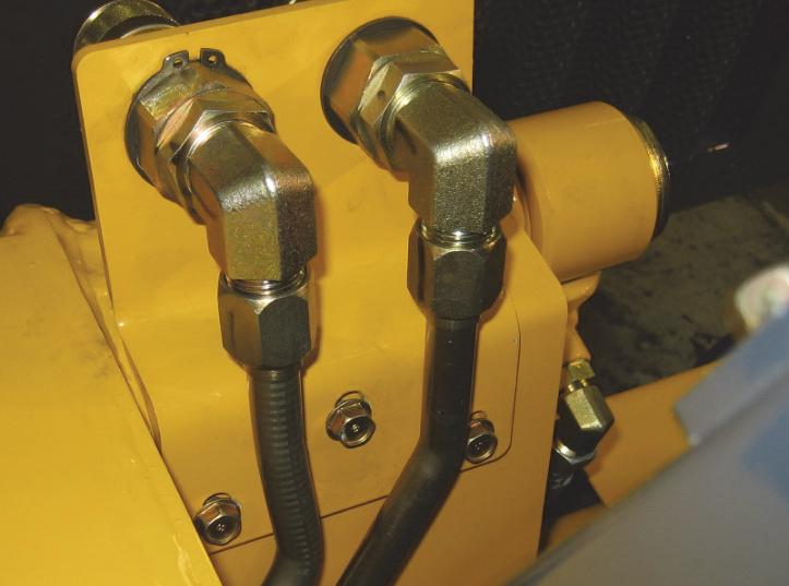
14.Remove both flat-faced couplers, 90° fittings and hardware from the lift arm.

15.Raise lift arm to gain access to the hydraulic hoses and the lift tube fittings.

16.Disconnect all hydraulic hoses attached to hydraulic tubes found underneath the lift arm.
18.Remove
Installation Procedure - Reverse the removal steps.
NOTE: After removing/replacing any components of the lift and tilt system, ALWAYS prime hydraulic system by operating the lift arm attachment (NO LOAD) slowly up and down for several cycles. Check system for hydraulic oil leaks following guidelines in the Safety chapter. Fill the hydraulic reservoir until fluid becomes visible in the hydraulic oil level sight gauge.
NOTE: Refer to the lift arm bushing installation procedure in this chapter if bushings require replacement.
Lift Arm Bushing Replacement WARNING
ALWAYS wear safety glasses with side shields when operating the machine or striking metal against metal. In addition, it is recommended that a softer (chip-resistant) material be used to cushion the blow. Failure to heed could lead to serious injury to eyes or other parts of the body.
Replacement Procedure
1.Remove the lift arm from the loader per the procedure in this chapter.
2.Use a punch to drive out the four upper lift arm bushings, two on each side of the lift arm.
NOTE: Applying heat to the upper lift arm bushings will release the adhesive and simplify removal.
3.Clean inside the opening to provide a smooth surface for installation of the new bushings.
4.Apply Loctite® 680 or its equivalent to the new lift arm bushings and press or drive them into the lift arm.
5.If replacing the bushings in each lower lift arm, use a punch to drive them out of the lift arm. Use a long-nosed plier to carefully remove the rubber wiper rods at the lower attachment bracket pivot.
6.Install new bushings by pressing them into place or using a rubber mallet to drive them into the lift arm.
7.Reinstall the lift arm on the loader per the procedure in this chapter.
Lift Arm Stop Installation and Adjustment Installation/Adjustment Procedure
NOTE: Lift arm stops should be shimmed as needed to ensure a gap of no more than 1/8" (3 mm) between the stops and the lift arm when the lift arm is fully lowered.
1.Lower lift arm and measure any gap between the stop and lift arm.
NOTE: It will be necessary to add one shim for every 1/8" (3 mm) gap.
2.Raise lift arm and engage the lift arm support device.
3.Remove one capscrew on the lift arm stop attached to the front of the chassis that needs adjustment.
4.Install shim(s) behind the rubber stop and secure with resecure the stop to the chassis. Use removable Loctite® 242 or equivalent retaining compound.
5.Start the engine and lower the lift arm. Verify gap and repeat procedure as needed.

Mainframe Components - DPF Models
1TIE/CABLE
2CLAMP/HOSE
3NUT/FLLSUF
4LN
5FUEL SENDER GASKET
6CAP ASSEMBLY-FILLER
7SENDER
8PLUG
9PLUG
10FILTER/VENT
11COVER/AXLE ACCESS
12COVER/CHAINCASE ACCESS
13COVER/OIL PAN
14DOWN STOP
15VENT/REMOTE
16PLATE/VALVE MOUNT
17KICK PLATE
18THWH TR
19LN FL SERR
20LN FL SERR
21CAP/FUEL FILLER
22STRAINER/FUEL
23CS FLAT HD
24COVER
25SHIM
26HOSE /FUEL
27FITTING/ST
28CHASSIS/WELDMENT
29PLATE/COVER
30FUEL TANK
31PLATE/FUEL SEPARATOR
32FITTING/90
Mainframe Components - Non-DPF Models
1TIE/CABLE
2CLAMP/HOSE 3NUT/FLLSUF
4LN
5FUEL SENDER GASKET
6CAP ASSEMBLY-FILLER
7SENDER
8PLUG 9PLUG 10FILTER/ VENT
11COVER/AXLE ACCESS
12COVER/CHAINCASE ACCESS
13FUEL TANK
14COVER/OIL PAN 15DOWN STOP
16VENT/REMOTE 17PLATE/VALVE MOUNT
18KICK PLATE
19THWH TR
20NUT/FLRSUF
21CS FLAT HD
22COVER
23SHIM
24HOSE /FUEL
25CHASSIS
26PAN, BELLY
27BOLT/CARRIAGE
28BOLT/CARRIAGE
29BOLT/CARRIAGE
30THWH TC USL
31HWHMS
32HWHTRS TAP/R
33HN
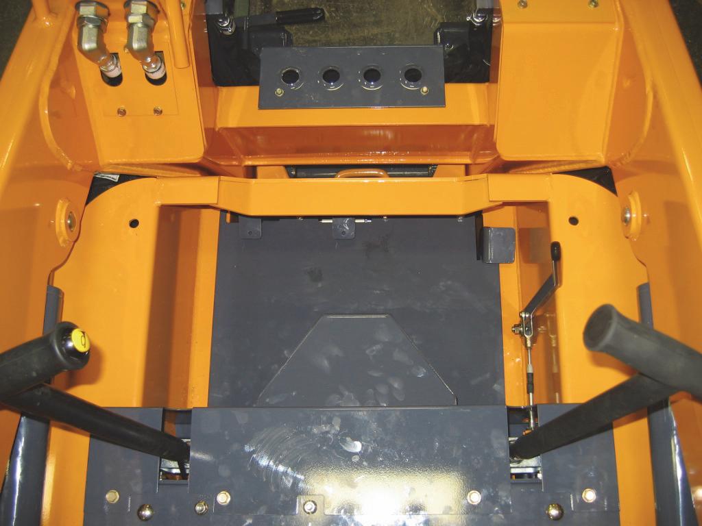
Floor Covers and Kickplate Removal and Installation
The floor covers and kickplate may be removed for access to handle assemblies, control linkages and connections to control rods, cables, tubes and hoses.


Warning
BEFORE beginning this service procedure, perform the following SAFETY procedures:
■ Remove attachment from lift arm.
■ Raise lift arm, engage lift arm support device.
■ Shut off the engine.
■ Tilt back ROPS/FOPS until lock engages. (For detailed instructions, refer to the Safety chapter of this manual.)
Removal Procedure - T-Bar floor bracket per the procedure in the Controls chapter.
1.Remove four capscrews securing the upper floor plate to the kick plate and control mount. Pull the upper floor plate up and out around the foot throttle pedal and auxiliary pedal (if so equipped).
2.On the lower floor plate, disconnect the auxiliary hydraulics cable from the auxiliary pedal and the
3.Disconnect the foot throttle pedal electrical harness from the throttle pedal.
4.Remove the capscrews, two on the auxiliary pedal assembly, securing the lower plate to the chassis. Pull the lower floor plate with the throttle pedal and auxiliary hydraulic pedals out the loader.
Kickplate
Removal Procedure - Hand/Foot
Warning
BEFORE beginning this service procedure, perform the following SAFETY procedures:
■ Remove attachment from lift arm.
■ Raise lift arm, engage lift arm support device.
■ Shut off the engine.
■ Tilt back ROPS/FOPS until lock engages. (For detailed instructions, refer to the Safety chapter of this manual.)

1.On the linkage cover, remove four capscrews securing the linkage cover to the kickplate. Two of the four capscrews are found at the front of the loader between and above the dirt clean-out openings and remove the linkage cover.


Installation Procedure - Reverse the removal

6.Pull the kickplate forward and up to remove it from the loader.
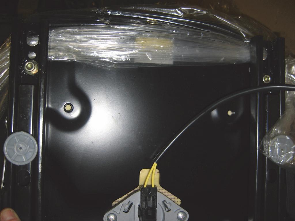
Fuel Sensor Removal and Installation
Removal Procedure
Warning
BEFORE beginning this service procedure, perform the following SAFETY procedures:
■ Shut off the engine. (For detailed instructions, refer to the Safety chapter of this manual.)
1.Open the engine access cover and lock open the rear grille.

2.Locate the fuel level sensor right of the fuel tank cap.
3.Drain the fuel tank into a clean approved container. Drain the fuel below the sensor mounting (½ full).
4.Disconnect the two wires from the sensor.
5.Remove the five screws securing the sensor, then remove the sensor and gasket from the tank.

Installation Procedure
1.Clean old gasket adhesive off the fuel tank.
2.Match the holes in the new gasket to the holes on the fuel tank.
3.Install new gasket using Form-A-Gasket #7651211 (or equivalent) to seal sensor opening on fuel tank.
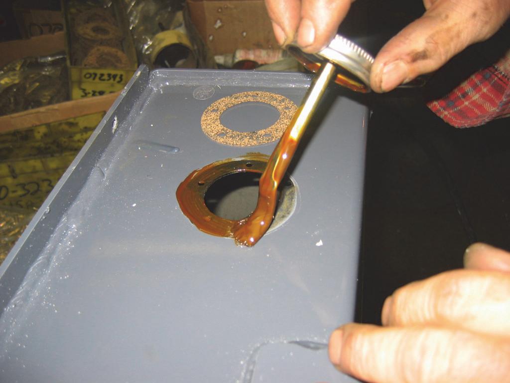
7.Attach the #25 (brown) wire to center stud with a nut, and the #0 (black) wire to ground stud with the fifth screw.
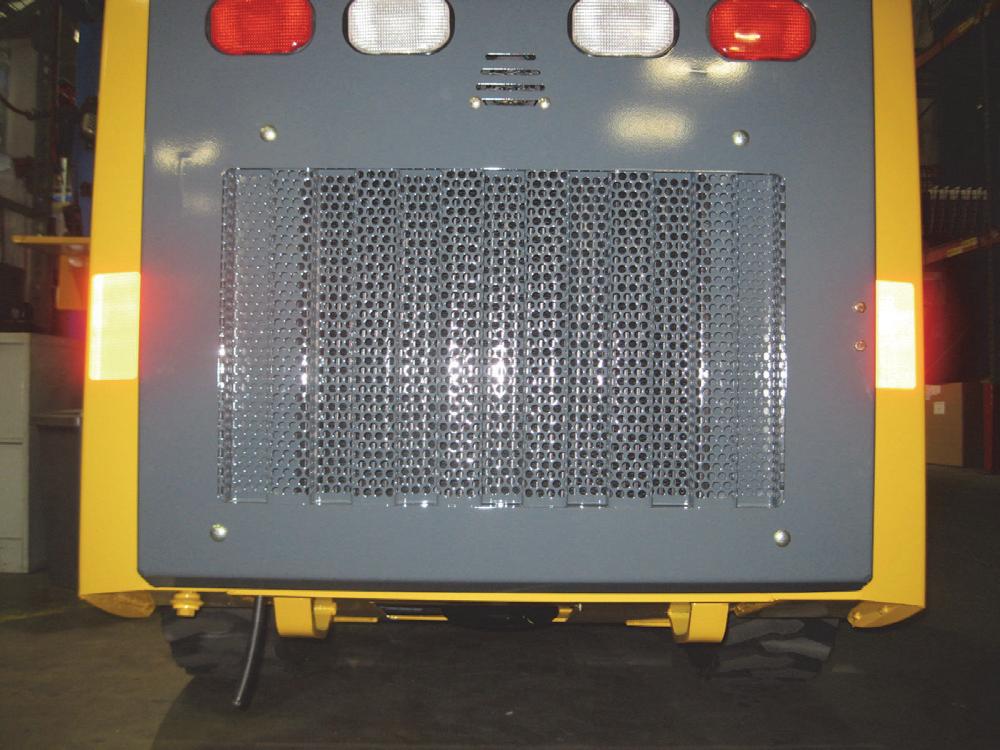
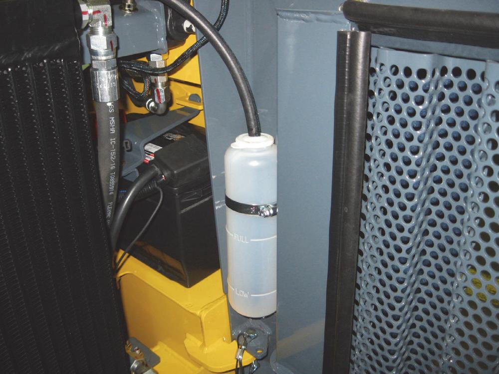
Rear Grille Removal and Installation
The rear grille is bolted onto the chassis and can be removed to perform work on the cooling system, engine, engine fan and shrouds.
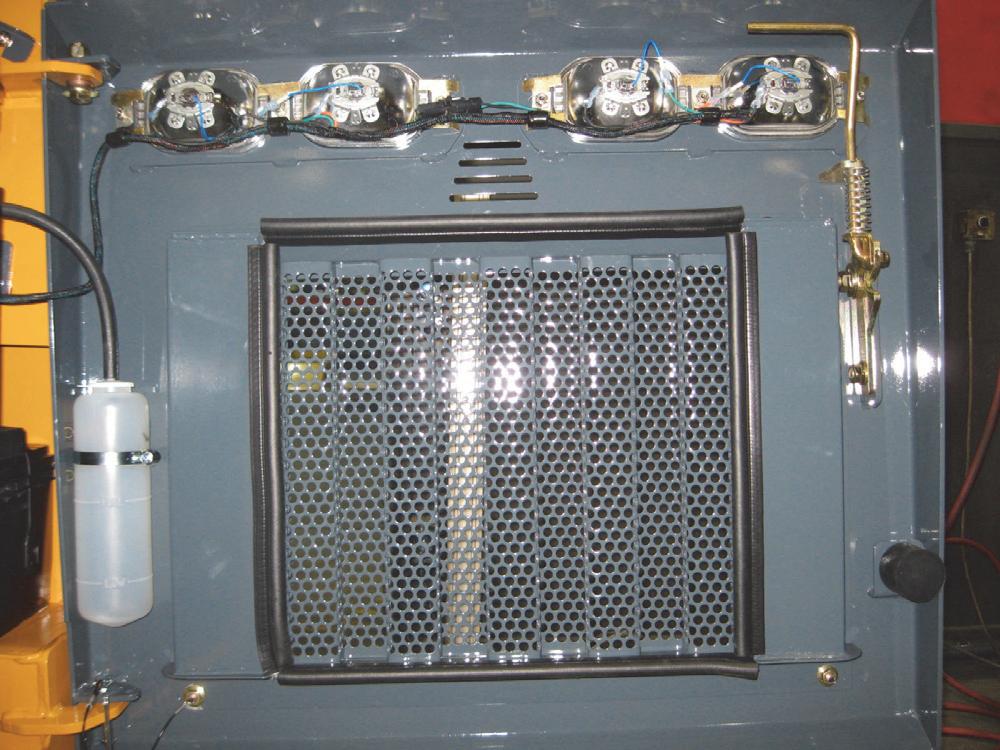
Removal Procedure
1.Open the engine access cover and lock open the rear grille.
2.Remove the hose from the top of the coolant recovery bottle secured to the rear grille.
5.Install new gasket using Form-A-Gasket #7651211 (or equivalent) to the five screws.

6.Install the five screws through the sensor into the fuel tank. DO NOT OVERTIGHTEN.

3.Disconnect the tail lights wire harness and free the harness from the rear grille.
4.Attach a suitable hoist of adequate capacity and a positive locking mechanism able to support the rear grille or equivalent to the rear grille.
Rear Grille Latch Removal and Installation


Removal Procedure

1.Open
Introduction
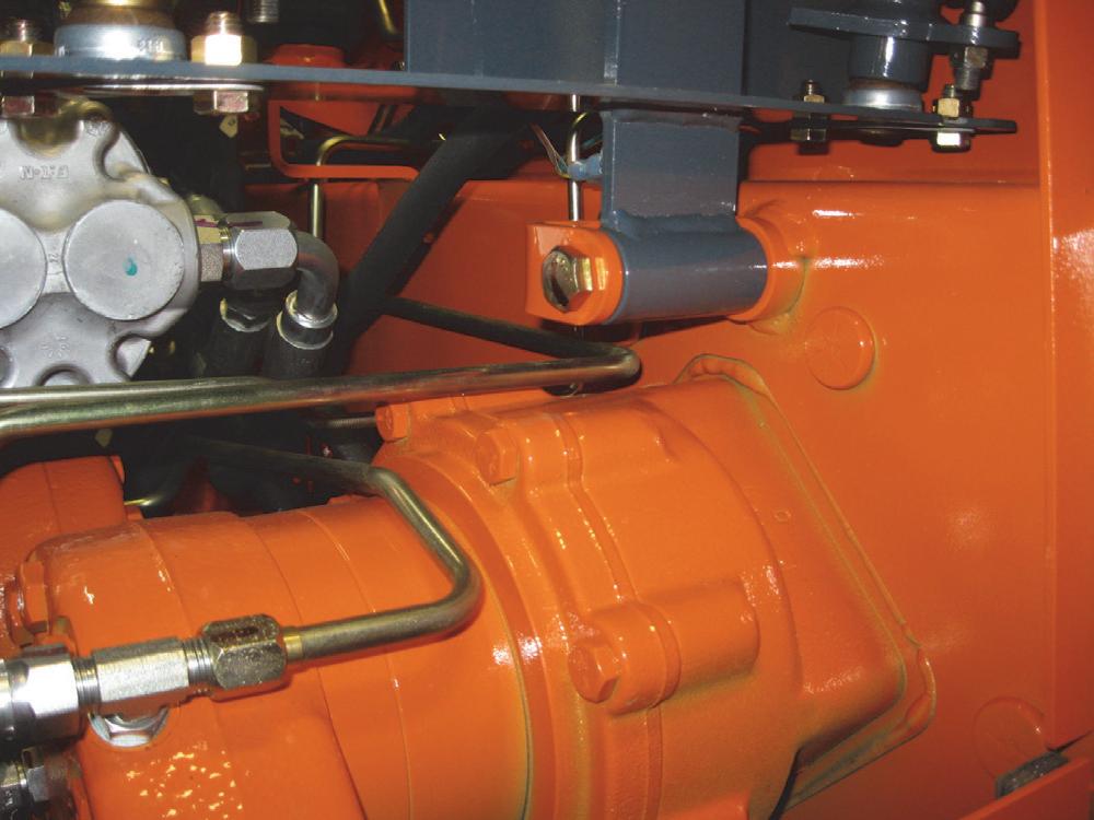
This chapter covers removal, installation, assembly and adjustment procedures for wheel drive system components on Gehl R105 and Mustang 1050R model skid-steer loaders. Wheel drive components covered in this chapter are shown below.
Gehl R105 and Mustang 1050R model skid-steer loaders are equipped with a hydrostatic pump assembly coupled to the diesel engine, providing hydrostatic power to the two fixed-displacement hydrostatic drive motors. The drive motors are directly connected to chaincases. Each motor drives one set of wheels on each side of the loader through a chain and sprocket system.
Service procedures related to the hydrostatic pump and drive motors can be found in the Hydrostatic System chapter.
Wheel Drive Components
INSTRUCTIONS
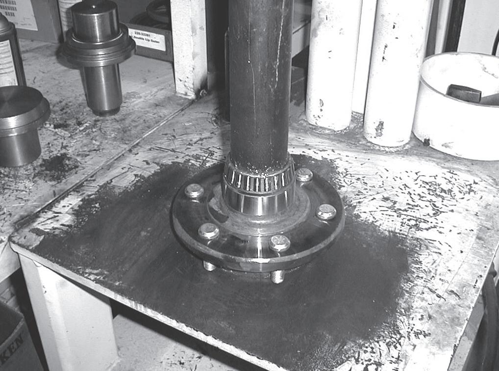
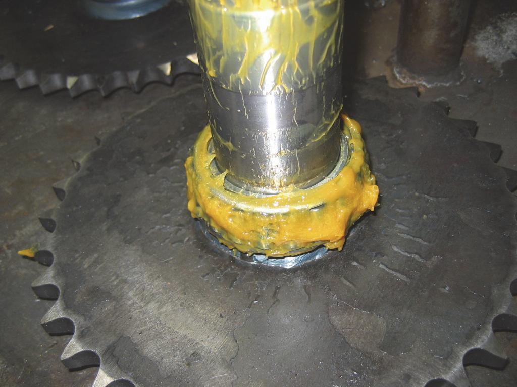
STEP 1. TIGHTEN HEX NUT (653102) TO 100 FT LBS TO PRESS BEARINGS IN PLACE. USE RUBBER FACED HAMMER TO APPLY A SHARP BLOW TO OUTSIDE HUB OF AXLE.
STEP 2. USE NUT RUNNER OR LIKE TOOL TO ROTATE AXLE
5-10 REVOLUTIONS TO HELP SEAT BEARINGS.
STEP 3. BACK OFF NUT UNTIL WASHER (400-32535) IS FREE FROM PRESSURE.
STEP 4. RE-TIGHTEN HEX NUT (653102) TO 30 FT LBS AND THEN BACK OFF TO NEAREST SLOT ALIGNMENT WITH COTTER PIN HOLE. IF NUT SLOT LINES UP WITH HOLE AT 30 FT LBS USE THAT SLOT.
STEP 5. INSTALL COTTER PIN (651160).
1BOLT/HUB
2CONE/BEARING
3CUP/BEARING
4ASSY/ROLLER CHAIN 80K 52 PITCHES
5ASSY/ROLLER CHAIN 80K 64 PITCHES
6SEAL/OIL
7PLATE/MOTOR MOUNT
8ASSEMBLY/AXLE AND LUG BOLT
9NUT/LUG
10NUT/HEX FLANGED TOP LOCK
11O-RING
12RING/SNAP INTERNAL
13SPROCKET/MOTOR
14SPROCKET/AXLE
15WASHER/SPECIAL
16WASHER/BACKING
17PIN/COTTER
18SCREW/CAP
19NUT/HEX SLOTTED
Drive Chain Adjustment
Skid-steer loader drive chain tension should be checked every 1000 hours of operation.
Adjustment Procedure
Warning
BEFORE beginning this service procedure, perform the following SAFETY procedures: drive motor in the slots on the motor mounting plate to adjust chain tension.
■ Shut off the engine.
■ Raise and securely block the loader so all four tires are off the ground.
(For detailed instructions, refer to the Safety chapter of this manual.)
1.Remove the wheels and tires on the side of the loader to be serviced.
2.Remove screws on the chaincase access cover (between tires) to access the drive chain.
3.Drain the oil from the chaincase. See the procedure in the Lubrication chapter.
4.Correct chain deflection is ½" @ 20 lbs. force (13 mm @ 89 N) - halfway between the sprockets.
5.To adjust chain tension, loosen the locknuts on the drive motor on one side of the loader. Slide the
6.After the proper chain tension is obtained, retighten the locknuts on the drive motor.
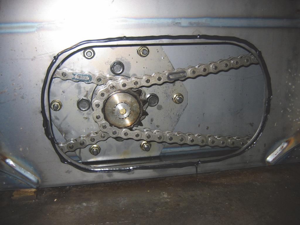
NOTE: The drive chain must have a minimum of 1/2" (13 mm) deflection; overtightening causes premature drive chain and sprocket wear.
7.Scrape off the old oil-resistant RTV and reapply new RTV. Reinstall the access cover.

8.Remove the fill plug on the chaincase access cover.
9.Refill the chaincase oil until the oil is up to the fill plug.
10.Reinstall the wheels and tires. Axle nut torque is: 100 ft.-lbs. (136 N•m) to press the bearings into place. Loosen the nut, then retighten to 30 ft.-lbs. (41 N•m).
11.Repeat the adjustment procedure for the other side.
Axle Housing Assembly Removal and Installation
Removal Procedure
Warning
BEFORE beginning this service procedure, perform the following SAFETY procedures:
■ Remove attachment from lift arm.
■ Raise and securely block the loader so all four tires are off the ground.
■ Raise lift arm; engage lift arm support device.
■ Shut off the engine.
■ Tilt back ROPS/FOPS until lock engages. (For detailed instructions, refer to the Safety chapter of this manual.)
1.Remove the lug nuts (120 ft-lbs.) (163 N•m), on the wheels and tires on the side of loader being serviced.
2.Drain the oil from the chaincase. See the procedure in the Lubrication chapter.
3.Remove the floor cover(s) per the procedure in the Mainframe chapter for access to the front axle access covers. Rear axle access covers are behind the drive motors on the chaincase housing.
6.Inside the loader, remove the screws on the axle access cover on each axle to be serviced.
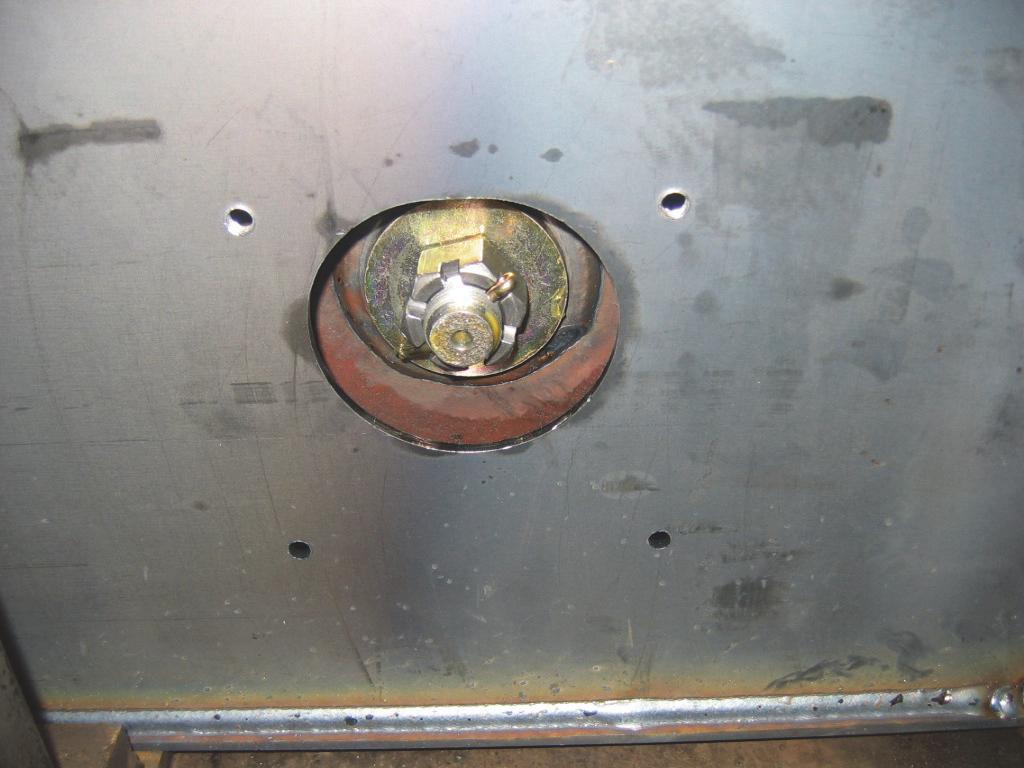

7.Remove a large cotter pin on a slotted axle nut on the axle hub.
4.Remove the screws on the chaincase access cover (between tires) to access the drive chain.
5.Remove the drive chains per the procedure in this chapter.
8.With a wrench, remove the slotted axle nut and the special washer beneath it.
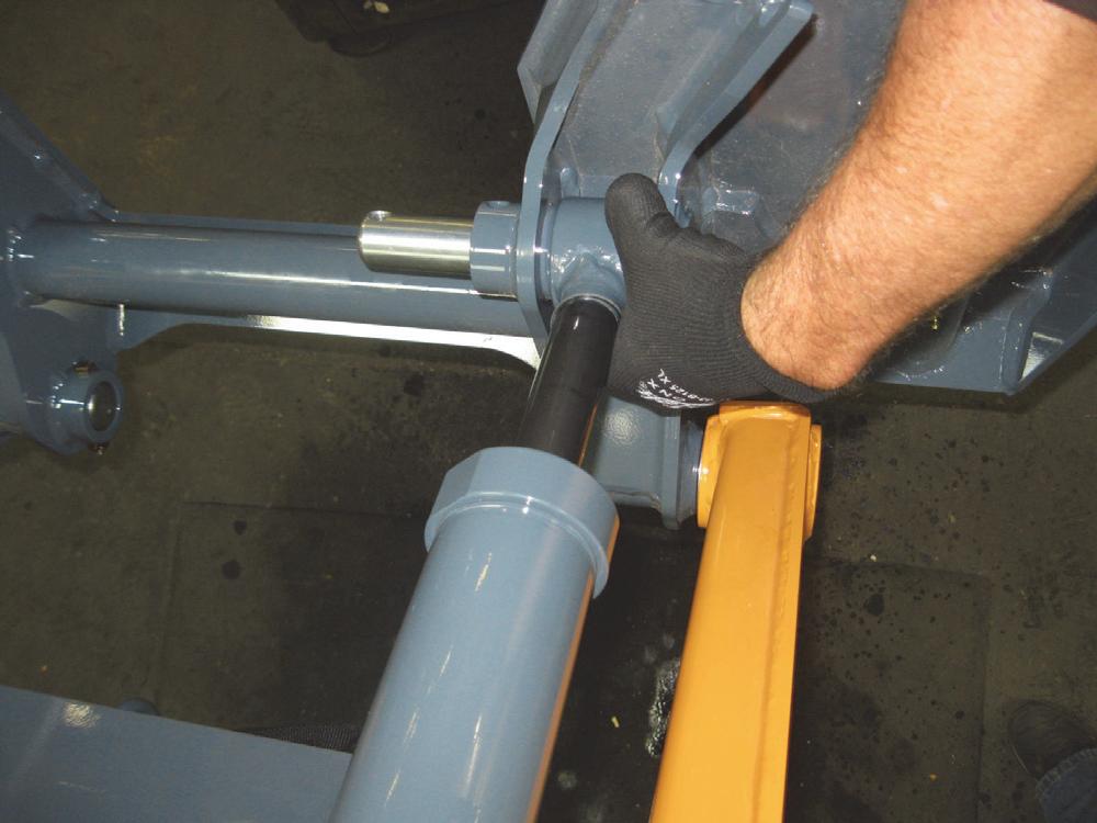
9.Use a slide hammer mounted the axle hub. A slight impact is needed to remove the axle from the inner bearing.

10.Attach a suitable hoist of adequate capacity and a positive locking mechanism able to support the axle assembly or equivalent to the axle assembly.
11.Remove the outer axle bearing and, if needed, the seal.
NOTE: Note the orientation of the bearing and the seal at remove for the correct reassembly procedure.
Installation Procedure
1.Install a new seal (if old was replaced) and an outer bearing on the axle.
NOTE: Pack the tapered bearings with grease before assembling.
2.Reinstall the inner bearing on the axle.
10.Install the cotter pin.
11.Install and adjust the drive chains per the procedure in this chapter.
12.Fill the chaincase with oil until it is up to the oil fill/level check plug.
13.Reinstall the chaincase access cover using oilresistant RTV sealant (or equivalent) between the cover and the chaincase.
14.Reinstall the wheels and tires. Wheel nut torque is: (120 ft-lbs.) (163 N•m).
Drive Chain Removal and Installation
3.Attach a suitable hoist of adequate capacity and a positive locking mechanism able to support the axle assembly or equivalent to the axle assembly and insert it into the axle sprocket in the axle housing weldment.
4.Slip the washer onto the axle hub. Tighten the slotted locknut on the axle hub to 100 ft.-lbs. (136 N•m) to press the bearings into place. Loosen the nut, then retighten to 30 ft.-lbs. (41 N•m).
5.Rotate the axle for 10 revolutions to help seat the bearings.
6.Strike the outside end of the axle with lead shot or a soft hammer to ensure the bearings are seated.
7.Recheck the slotted locknut on the axle hub is tightened to 100 ft.-lbs. (136 N•m).

8.Back off the slotted locknut until the nut is free from pressure.
9.Retighten the slotted locknut to 30 ft.-lbs. (41 N•m) then increase to alignment slot with the cotter pin hole. If the nut lines up with the cotter pin hole at 30 ft.-lbs. (41 N•m), then use that slot.
Removal Procedure
Warning
BEFORE beginning this service procedure, perform the following SAFETY procedures:
■ Shut off the engine.
■ Raise and securely block the loader so all four tires are off the ground. (For detailed instructions, refer to the Safety chapter of this manual.)
1.Remove the wheels and tires on the side of the loader being serviced.
2.Drain the oil from the chaincase. See the procedure in the Lubrication chapter.
3.Remove the screws on the chaincase access cover to gain access to the drive chain.
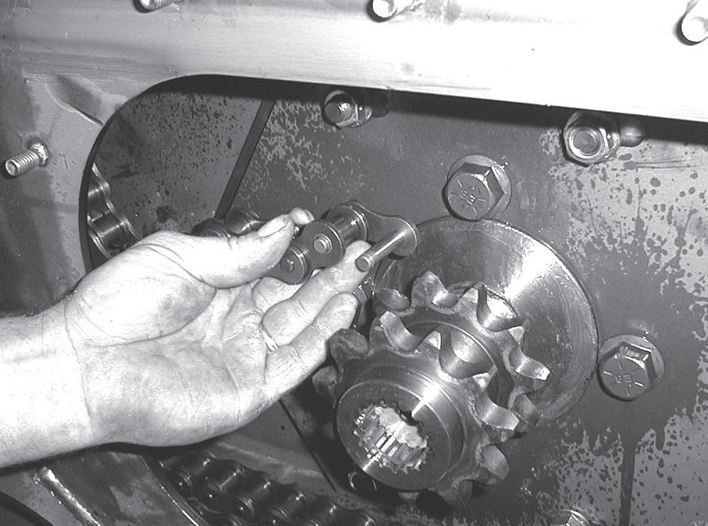
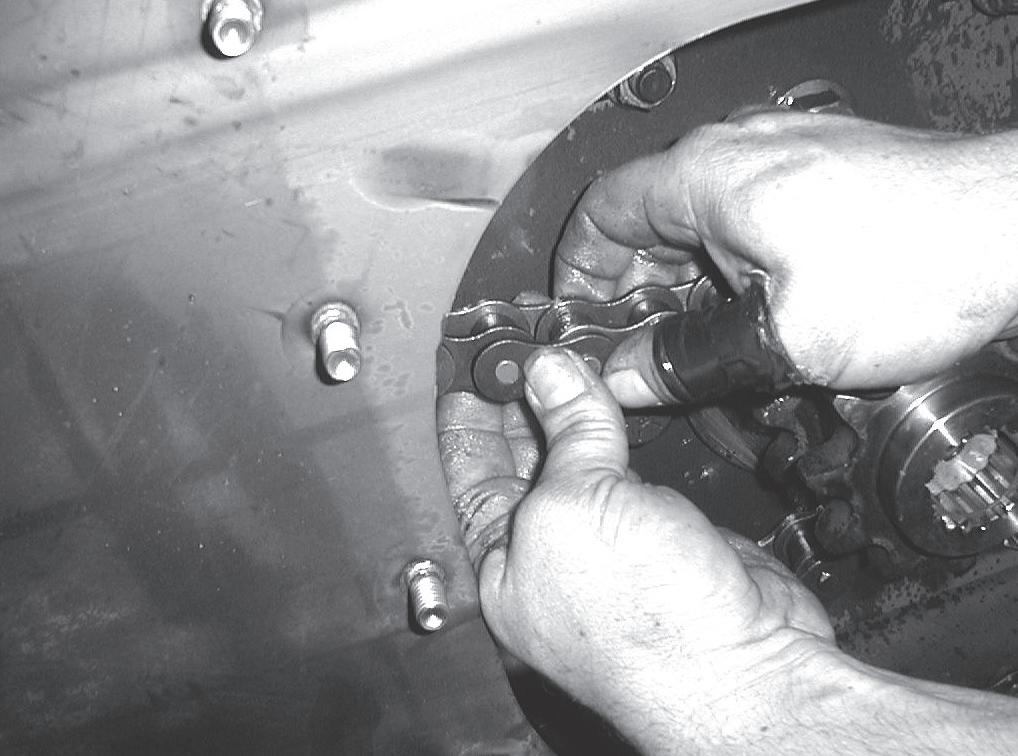
4.Split the drive chain by removing the connector pin and connector link. On the connector link, remove the sidebar, then pull the link out from the back of the chain. It may be necessary to rotate the drive chain for access to the connector link.
1.Wrap the chain around sprocket of the axle.
2.Wrap the chain around the drive motor sprocket.
3.Connect the drive chain with the connector link and sidebar.
4.Adjust the drive chain to the proper tension per the procedure in this chapter.
5.Install the chaincase access covers using oil-resistant RTV sealant (or equivalent) between the covers and chaincase. Refill the chaincase oil until the oil is up to the fill plug.
6.Reinstall the oil fill/level check plug.
7.Reinstall the wheels and tires. Wheel nut torque is: (120 ft-lbs.) (163 N•m).
Axle and Wheel Bearing Disassembly and Assembly
Disassembly Procedure
1.Remove the axle housing assembly per the procedure in this chapter.
2.Remove the outer bearing cone from the axle shaft.
3.Remove the axle shaft from the chassis per the procedure in this chapter.
4.Remove the inner bearing cone from the axle shaft.

5.Remove the axle seal and outer bearing cup from the axle housing assembly.
6.Turn housing assembly over and remove the inner bearing cup from the axle housing assembly.
Assembly Procedure
NOTE: Pack the tapered bearing cones with synthetic grease before assembling.
5.Remove the drive chain from the chaincase. Installation Procedure - Follow the Removal Procedure warnings first, then:
NOTE: When installing the left and right side drive chains, install the inside chain first.

Bearing Cups

2.Install the double-lip axle seal in the axle housing. Use suitable drivers or a press to countersink all components until they bottom out.
4.Place the axle shaft on a flat surface with the shaft in a vertical position. Press the bearing cone onto the axle shaft with a suitable driver or a press at a force of 6000 lbf. (26,7 kN). Note the orientation of the first bearing cone.


Bearing Cone
3.Turn the axle housing over and press an additional bearing cup into the other side of the axle housing with a force of 6000 lbf. (26,7 kN) using a bearing press.
Introduction
This chapter covers the removal, installation, assembly, and adjustment procedures for standard and optional controls on Gehl R105 and Mustang 1050R model skidsteer loaders.

Equipment Identification
Because there are a variety of options available for Gehl R105 and Mustang 1050R models, it is necessary to properly identify the controls before beginning the service procedures. Illustrations and photographs are provided with procedures to aid in servicing this equipment.
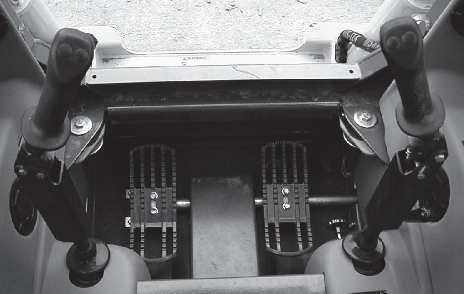
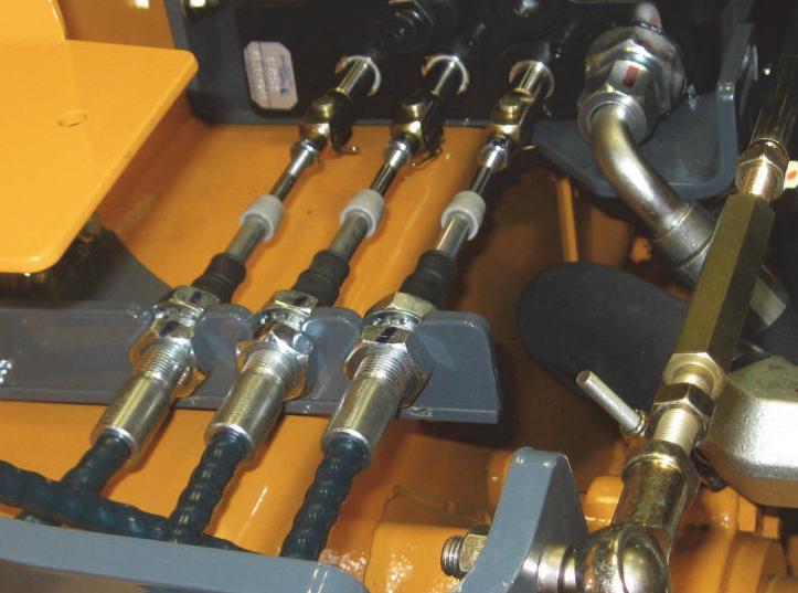
T-Bar Controls
On skid-steer loaders with “T-Bar Controls,” the left TBar operates the drive wheels and pumps for both sides of the skid-steer loader. The right T-Bar controls the lift and tilt functions of the lift arm and bucket. Engine speed is controlled by the hand and/or foot throttles. Standard-flow auxiliary hydraulics is controlled by a foot pedal.
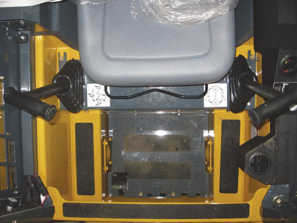
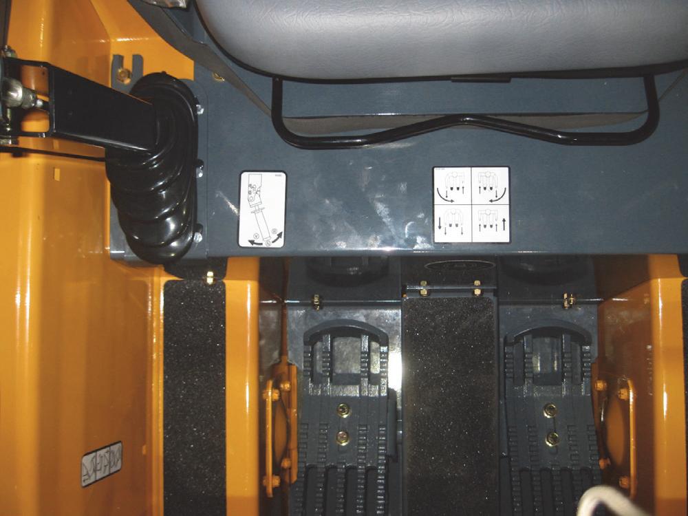
Hand/Foot Controls
On loaders with “Hand/Foot Controls”, the left and right drive control handles operate independently of each other. With both control handles pushed forward together, the loader moves forward, but push either one farther forward than the other and the loader turns. Separate foot pedals control the lift and tilt functions of the lift arm and bucket. Engine speed is controlled with a hand throttle on the right instrument panel. The auxiliary hydraulics are actuated by the right control handle.
Wheel Drives, Foot Throttle and Lift Tilt Components - T-Bar - DPF Models
NOTE:
1. USE THESE ITEMS TO PLUG UN-USED HOLES IN KICKPLATE TO HELP REDUCE OPERATOR SOUND LEVELS.
Wheel Drives, Foot Throttle and Lift Tilt Components - Parts Listing - T-Bar - DPF Models
1BEARING/FLANGE MOUNT/FM
2BEARING/FLANGE MOUNT/FL
3BOOT COVER/RH
4BOOT COVER/LH
5BUSHING/SUPER OILITE
6BUSHING/OILITE
7BUSHING/OILITE
8BALL JOINT
9BALL/JOINT ASSY
10FW
11NUT/FLLSUF
12LN
13LN
14LN
15CS FL LOCK
16HFS
17NUT/FLRSUF
18HFS
19DRIVE CONTROL PIVOT WELD
20DRIVE CONTROL
21HLN INST
22T-BAR STOP
23CENTERING DEVICE
24LT HANDLE ASSY-GRIP
25RT HANDLE ASSY-GRIP
26CONTROL BRKT ASSY
27HYDRAULIC CNTRL SUPPORT
28ROD/CONTROL LIFT
29BRACKET/STIFFENER
30CONTROL MOUNT/WELDMENT
31BRACKET WELD/CONTRL MNT
32CABLE
33CLEVIS/SHORT
34CABLE MOUNT/WELDMENT
35LN FL SERR
36LN FL SERR
37NUT/FLRCL
38HN CENTERLOK
39PIN/CLEVIS
40PIN/CLEVIS
41PIN/CLIP/RUE
42AUXILIARY PEDAL
43YOKE
44CONTROL ROD
45SCREW F/WHIZLOCK
46SPACER
47BOOT/T-BAR
48BUSHING
49FOOT THROTTLE/ELECTRIC
50CONTROL MOUNT
51PLATE/FLOOR
52FOAM/FOOT PLATE/T-BAR 53HWHTFS
Wheel Drives, Foot Throttle and Lift Tilt Components - T-Bar - Non-DPF Models
ADJUST BOLT UNTIL FOOT
PIVOT WELDMENT CONTACTS BOLT HEAD WHEN AUXILIARY SPOOL IS IN FULL FLOW POSITION
NOTE:
1. USE THESE ITEMS TO PLUG UN-USED HOLES IN KICKPLATE TO HELP REDUCE OPERATOR SOUND LEVELS.
Wheel Drives, Foot Throttle and Lift Tilt Components - Parts Listing - T-Bar - Non-DPF Models
1BEARING/FLANGE MOUNT/FM
2BEARING/FLANGE MOUNT/FL
3BOOT COVER/RH
4BOOT COVER/LH
5BUSHING/SUPER OILITE
6BUSHING/OILITE
7BUSHING/OILITE FLANGED
8BALL JOINT
9BALL/JOINT ASSY
16HFS
17NUT/FLRSUF
18HFS
19CABLE
20THROTTLE PEDAL WELDMENT
21DRIVE CONTROL PIVOT WELD
22DRIVE CONTROL
23BRACKET/CABLE MOUNT
24HLN INST
25T-BAR STOP
26CENTERING DEVICE
27LT HANDLE ASSY-GRIP
28RT HANDLE ASSY-GRIP
29SCREW/SHOULDER
30CONTROL BRKT ASSY
31HYDRAULIC CNTRL SUPPORT
32ROD/CONTROL LIFT
33BRACKET/STIFFENER
34CONTROL MOUNT
35BRACKET WELD/CONTRL MNT
36CONTROL MOUNT
37PLATE/FLOOR
38CABLE
39CLEVIS/SHORT
40CABLE MOUNT
41FOAM/FOOT PLATE/T-BAR
42YOKE/CLEVIS
43LN FL SERR
44NUT/FLRCL
45HN CENTERLOK
46PIN/CLEVIS
47PIN/CLEVIS
48PIN/CLIP/RUE
49AUXILIARY PEDAL
50YOKE
51CONTROL ROD
52SCREW F/WHIZLOCK
53SPACER
54SPRING
55BOOT/T-BAR
Wheel Drives, Auxiliary Hydraulics and Lift Tilt Components - Hand/Foot Models
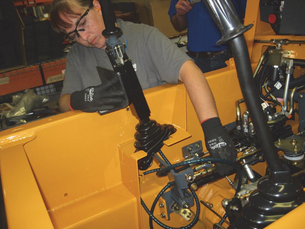
Control Handle Removal and Installation
Warning
BEFORE beginning this service procedure, perform the following SAFETY procedures:
■ Remove attachment from lift arm.
■ Raise lift arm; engage lift arm support device.
■ Shut off the engine.
■ Tilt back ROPS/FOPS until lock engages. (For detailed instructions, refer to the Safety chapter of this manual.)
Removal Procedure - T-Bar Models
1.Remove the kickplate per the procedure in the Mainframe chapter.
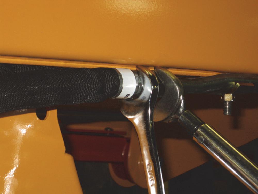
2. Right T-Bar: Remove the locknut and t-bar stop on the studded rod end attached to the tilt control rod at the control handle. Pull the rod end out of the control handle and remove the control handle. Left T-Bar: Remove the locknuts and capscrews securing the control handle to the drive control weldment and chassis.
4.Remove the left control handle.
Important
Note the wire terminal connections in the electrical connector for reassembling the control handle if replacing the handle’s electrical cable.
Installation Procedure: Follow all warnings first, then reverse the removal steps (see NOTE below).
NOTE: When the control handle is installed, and if the control rod(s) are adjusted correctly, the control handle shafts have a 10° forward tilt. If changes are needed, refer to the “Control Handle Position Adjustment” procedure in this chapter.
Removal Procedure - Hand/Foot Models
1.Remove the floor cover and kickplate per the procedure in the Mainframe chapter.
2. Right Handle: Remove the locknut and studded rod end and the shock absorber attached at the far left end of the control handle. Remove the large capscrew and locknut securing the control handle to the pivot weldment. Disconnect the auxiliary hydraulics control cable inside and below the hand grip and pull cable out from the bottom. Remove the control handle.
Installation Procedure: Follow all warnings first, then reverse the removal steps (see NOTE below).
NOTE: When the control handle is installed, and if the control rod(s) are adjusted correctly, the control handle shafts have a 10° forward tilt. If changes are needed, refer to the “Control Handle Position Adjustment” procedure in this chapter.


Control Handle Position Adjustment
Control handles are adjusted two ways for proper operation: a vertically straight appearance and the handle orientation.
Adjustment Procedure
Warning
BEFORE beginning this service procedure, perform the following SAFETY procedures:
■ Remove attachment from lift arm.
■ Raise lift arm; engage lift arm support device.
■ Shut off the engine.
■ Tilt back ROPS/FOPS until lock engages. (For detailed instructions, refer to the Safety chapter of this manual.)
1.Remove the floor cover and kickplate per the procedure in the Mainframe chapter.
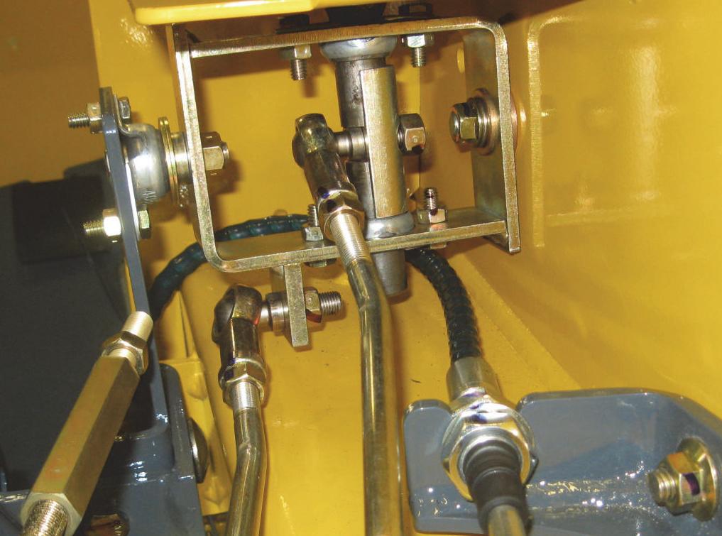
2. T-Bar Models; Left control handle: Install two 3/ 8” (9.5 mm) alignment rods, one through the pivot weldment and control weldment, and the other through the control weldment and the t-bar pivot. Loosen the jam nuts on the center control rod and adjust the rod between the rod ends. Retighten the jam nuts. Next, loosen the jam nuts on the turnbuckles and adjust the turnbuckles on the hydrostatic pump arm rods to obtain a 10° forward tilt to the left handle. Retighten the turnbuckle jam nuts. Remove the temporary alignment rods. BE SURE the adjustment allows for full activation of the hydrostatic pump arm in both directions of operation.
NOTE: If control handle does not return to NEUTRAL position after adjustment, refer to the “Neutral Centering Device” adjustment procedure in this chapter.
3. T-Bar Models; Right control handle: Remove the locknut and t-bar stop on the studded rod end attached to the tilt control rod at the control handle. Pull the rod end out of the handle. Remove the locknut on the studded rod end attached to the lift control rod and the bottom of the t-bar pivot. Loosen the jam nuts on the lift and tilt controls rods and adjust rod ends to obtain a 10° forward tilt to the control handle. After adjustment is made, retighten the jam nuts against the rod ends and reconnect the control rods to the handle and pivot with their hardware. BE SURE the adjustment allows for full activation of the control valve in both directions of handle operation.
4. Hand/Foot Models; Left and Right Control Handles: Loosen the jam nuts and adjust two turnbuckles on the hydrostatic pump arm rods to obtain a 10° forward tilt to the control handles. Retighten the turnbuckle jam nuts. BE SURE the adjustment allows for full activation of hydrostatic pump arms in both directions of handle operation.


Turnbuckles
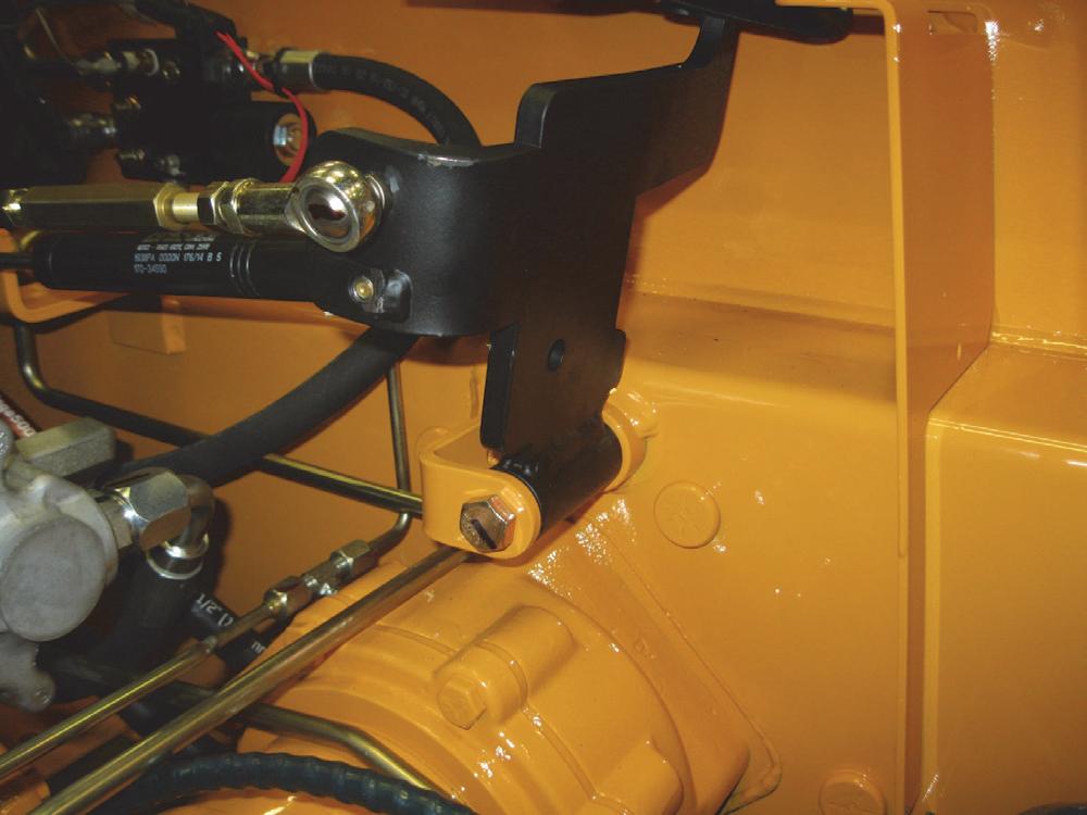
3.Remove the locknuts on the rod ends attaching the hydrostatic pump arms and central control arm to the pivot weldment.
Pivot Tube Weldment Removal and Installation - T-Bar
Pivot tube exploded views are good references for the pivot tube’s removal and installation procedures. Refer to these views for locations of components in the assemblies.
Removal Procedure
Warning
BEFORE beginning this service procedure, perform the following SAFETY procedures:

■ Remove attachment from lift arm.
■ Raise lift arm; engage lift arm support device.
■ Shut off the engine.
■ Tilt back ROPS/FOPS until lock engages.
(For detailed instructions, refer to the Safety chapter of this manual.)
1.Remove the floor cover and kickplate per the procedure in the Mainframe chapter.
2.Remove the control handles per the procedure in this chapter.
4.Remove the locknut and washer securing the neutral centering device to the pivot weldment.
5.Remove hardware on the pivot weldment securing the weldment on the left and right sides.
6.Remove the pivot weldment from the loader.
NOTE: It’s recommended that good notes be taken to aid in reassembly. If necessary, mark the holes on the levers.
Installation Procedure: Follow all warnings first, then reverse the removal steps.
1.Attach all the control rods and centering devices to the appropriate levers on the pivot tube assembly.
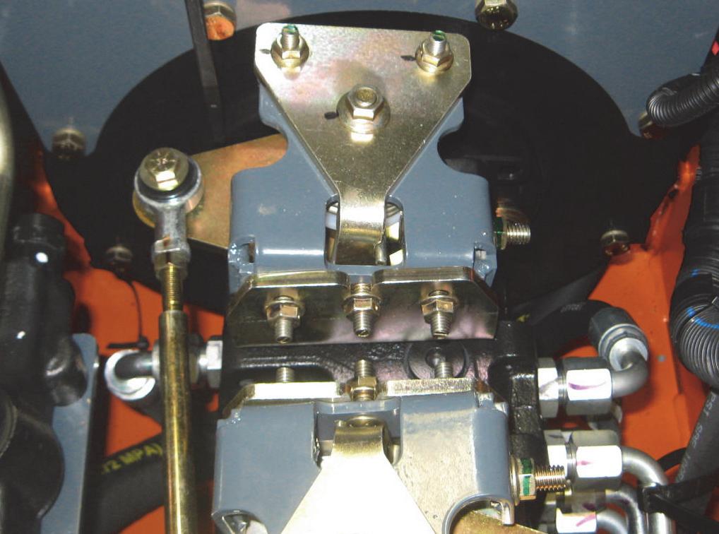

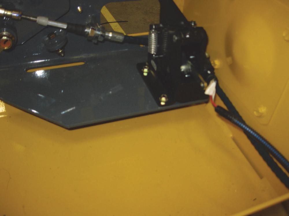
Neutral Centering Device and Pump Arm Removal and Installation
The neutral centering device and pump arm weldment are designed to be interchangeable on the front and rear hydrostatic pumps.
Remove Procedure
Warning
BEFORE beginning this service procedure, perform the following SAFETY procedures:
■ Remove attachment from lift arm.
■ Raise lift arm; engage lift arm support device.
■ Shut off the engine.
■ Tilt back ROPS/FOPS until lock engages. (For detailed instructions, refer to the Safety chapter of this manual.)
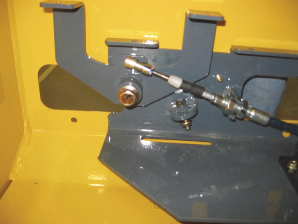
1.Disconnect the hydrostatic pump arm control rods from the pump arms.
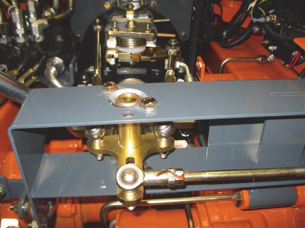
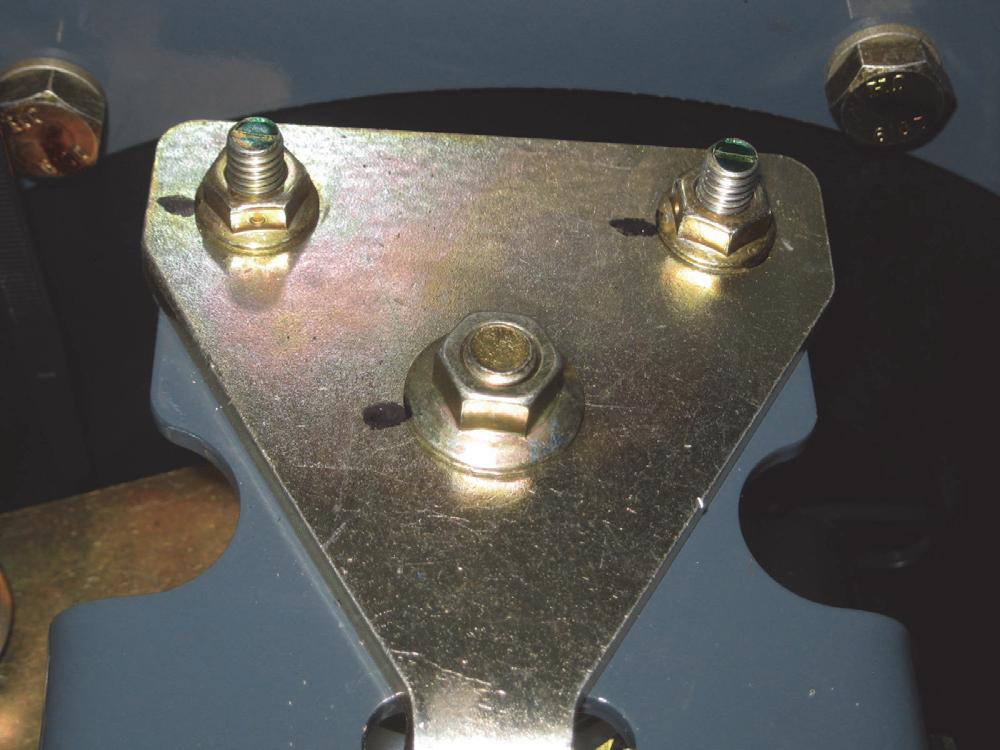
2.Remove the horizontal locknuts and capscrews securing the upper bracket to the lower bracket. Loosen the center locknut until the upper bracket lifts free.

4.Remove capscrews securing the pump arm retainer and pump arm weldment to the hydrostatic pump shaft.
(For detailed instructions, refer to the Safety chapter of this manual.)
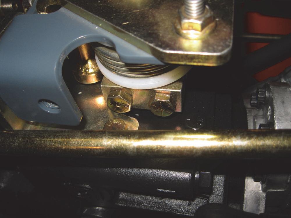
1.Rotate the neutral centering device, checking the centering torsion spring backlash.

2.Adjust torsion spring backlash by loosening three locknuts on the horizontal bolts.
5.Repeat steps 1-4 for the other neutral centering device.
Installation Procedure*: Follow all warnings first, then reverse the removal steps.
* After installation, perform the “Neutral Centering Device Adjustment” procedure in this chapter, BUT, if the control rods’ length were not altered and the rod end slips right in, then no adjustment should be necessary.

Neutral Centering Device Adjustment
Gehl R105 and Mustang 1050R skid-steer loaders come equipped with two neutral centering devices on the hydrostatic pump assembly. These devices allow the control handles and control arms to automatically return to NEUTRAL when the operator releases the control handles.
Adjustment Procedure
Warning
BEFORE beginning this service procedure, perform the following SAFETY procedures:
■ Remove attachment from lift arm.
■ Raise and block loader so the tires are off the ground.
■ Raise lift arm; engage lift arm support device.
■ Shut off the engine.
■ Tilt back ROPS/FOPS until lock engages.
3.Rock the upper bracket side-to-side to remove clearance between the torsion spring “legs”, neutral adjusting plate and the pump arm pin.
4.Retighten the three locknuts on the horizontal bolts.
5.Start the loader. Release the parking brake, lower the restraint bar down and depress the seat switch.
6.Run the loader at half throttle and check for a NEUTRAL setting of the hydrostatic pump arms. When the pump arms are in NEUTRAL, the tires MUST remain stationary.
7.To remove any noticeable tire creep, loosen the locknuts on bolts at the top of the centering device,
NOT the center bolt. Twist the upper bracket until any tire creep is eliminated. Retighten the locknuts.
Lift/Tilt Controls Removal and Installation
Warning
BEFORE beginning this service procedure, perform the following SAFETY procedures:
■ Remove attachment from lift arm.
■ Raise lift arm; engage lift arm support device.
■ Shut off the engine.
8.To test the operation of the control handle(s), move the control handle(s) forward and backward and allow the neutral centering devices to return the control handles to a NEUTRAL position.
■ Tilt back ROPS/FOPS until lock engages. (For detailed instructions, refer to the Safety chapter of this manual.)
Removal Procedure - Right T-Bar Control Handle valve. Loosen the jam nuts on the control cables and remove the lift and tilt cables from the loader.
1.Remove the locknut securing the studded rod end of the lift and tilt control rods to the control handle and pivot. Release the rod ends from the handle assembly.
2.Disconnect the lift and tilt control rods from the control valve spools by remove clip pins and clevis pins.

Installation Procedure: Follow all warnings first, then reverse the removal steps.
Remove Procedure - Hand/Foot Controls
1.Remove the floor cover and kickplate per the procedure in the Mainframe chapter.
2.Remove the clip pins and clevis pins on the short clevis at the foot controls pivot. Loosen the jam nuts on the control cables and slide the cable up and out.
Installation Procedure: Follow all warnings first, then reverse the removal steps.
Lift/Tilt Control Adjustment WARNING
BEFORE beginning this service procedure, perform the following SAFETY procedures:
■ Remove attachment from lift arm.
■ Raise lift arm; engage lift arm support device.
■ Shut off the engine.
■ Tilt back ROPS/FOPS until lock engages. (For detailed instructions, refer to the Safety chapter of this manual.)
Adjustment Procedure - T-Bar Controls
The lift and tilt control rod lengths can be adjusted to obtain proper position of the T-Bar. Refer to “Control Handle Position Adjustment” procedure in this chapter. The “Self-leveling Valve Adjustment” procedure in the Hydraulic System chapter is also related to the correct operation of the lift and tilt controls. Refer to this procedure as needed.

Adjustment Procedure - Hand/Foot Controls
1.Remove the floor cover and kickplate per the procedure in the Mainframe chapter.
2.With the lift and tilt spools in NEUTRAL position, adjust the lift and tilt control cables at the control valve so that both cables at the foot pedals are even and parallel to the kickplate. Tighten the hardware.
3.Reinstall the kickplate.
4.Check for full range of spool travel for both the lift and tilt cables.
5.Move the lift spool into detent (FLOAT) position.
6. On the lift pedal: Adjust the length of the lift control cable. Loosen the jam nut on the cable until the pedal is level and parallel to the floor plate.

7.Retighten the jam nut.
8. On the tilt pedal: Adjust the length of the tilt control cable. Loosen the jam nut on the cable until the tilt pedal matches the position of the lift pedal.
9.Retighten the jam nut.
Auxiliary Hydraulics Cable Removal and Installation
T-Bar models use a control cable between the auxiliary pedal and the control valve to actuate the auxiliary hydraulics. In Hand/Foot models, the actuation of the auxiliary hydraulics is in the right control handle.

Removal Procedure
Warning
BEFORE beginning this service procedure, perform the following SAFETY procedures: clip pin securing the auxiliary hydraulics cable to the main control valve spool.
■ Remove attachment from lift arm.
■ Raise lift arm; engage lift arm support device.
■ Shut off the engine.
■ Tilt back ROPS/FOPS until lock engages. (For detailed instructions, refer to the Safety chapter of this manual.)
1.Remove the floor cover and kickplate per the procedure in the Mainframe chapter.
5.Remove the cable. If replacing the auxiliary hydraulics control cable, remove the rod ends, washers and jam nuts from the old cable.
6. Hand/Foot Control Models Only: Remove the shoulder screw and washer attaching auxiliary control cable the right control handle. Loosen the jam nut on the auxiliary cable, and remove the cable from the control handle.
Auxiliary Hydraulics Cable Adjustment
The auxiliary hydraulics cable should be adjusted so that the hydraulic control valve is engaged when the auxiliary foot pedal is depressed for T-Bar Models, or, the right control handle cable is locked in ON position for Hand/Foot models. Refer to the exploded views for identifying the parts and components.
Warning
BEFORE beginning this service procedure, perform the following SAFETY procedures:
■ Remove attachment from lift arm.
■ Raise lift arm; engage lift arm support device.
■ Shut off the engine.
Installation Procedure: Follow all warnings first, then reverse the removal steps.*
* For cable adjustment, refer to the “Auxiliary Hydraulics Cable Adjustment” procedure in this chapter.
■ Tilt back ROPS/FOPS until lock engages. (For detailed instructions, refer to the Safety chapter of this manual.)
Adjustment Procedure - T-Bar Controls
1.Remove the floor cover and kickplate per the procedure in the Mainframe chapter.
2.With the auxiliary hydraulics spool in NEUTRAL position, loosen jam nuts on the auxiliary cable at the pivot foot pedal and adjust so that the foot pedal is horizontal (level).
3.Disconnect the ball joint on the cable from the auxiliary pedal assembly by removing the hex nut.
4.Twist the ball joint in to tighten or out to loosen the auxiliary hydraulics cable (most adjustments will require a tightening of the cable.)
5.Retighten the jam nut snug against the ball joint to set the adjustment.
6.Reinstall the ball joint and hex nut and secure it to the auxiliary hydraulics pedal assembly.
7.Check for full range of spool travel. Retighten the jam nuts on the auxiliary cable.
8.Check operation of auxiliary hydraulics cable by using an appropriate attachment.
Adjustment Procedure - Hand/Foot Controls
1.Remove the floor cover and kickplate per the procedure in the Mainframe chapter.
2.On the control valve, place the auxiliary hydraulics spool in NEUTRAL position.
3.At the right control handle, loosen the jam nuts securing the auxiliary cable to the control handle weldment.
Electric Foot Throttle Pedal Removal and Installation - DPF Models
Removal Procedure - T-Bar Controls
Warning
BEFORE beginning this service procedure, perform the following SAFETY procedures:
■ Shut off the engine.
■ Tilt back ROPS/FOPS until lock engages. (For detailed instructions, refer to the Safety chapter of this manual.)
1.Remove the floor cover and kickplate per the procedure in the Mainframe chapter.
4.Right the hand grip of the right control handle to its most vertical position and check that the auxiliary spool end at the control valve engages fully.
5.Check for full-range spool travel in the auxiliary hydraulics spool on the control valve by using an appropriate attachment.
2.At the foot throttle pedal, unplug the electrical harness that powers the pedal.
3.Remove capscrews and locknuts securing the electric foot pedal to the plate.
Installation Procedure: Follow all warnings first, then reverse the removal steps.
Handle Throttle, Hand Throttle Cable and Throttle Rod Removal and InstallationNon-DPF Models
Removal Procedure
Warning
BEFORE beginning this service procedure, perform the following SAFETY procedures:
■ Remove attachment from lift arm.
■ Raise lift arm; engage lift arm support device.
■ Shut off the engine.
■ Tilt back ROPS/FOPS until lock engages. (For detailed instructions, refer to the Safety chapter of this manual.)
1.Remove the floor cover and kickplate per the procedure in the Mainframe chapter.
2.Remove the clevis pin and cotter pin securing the hand throttle cable yoke to the throttle handle grip.
5.At the engine mount weldment, remove the clevis pin and cotter pin on the yoke attaching the other end of the throttle cable to the hand throttle pivot.
3.Remove the carriage bolt, locknut, friction washer and spring washers securing the hand throttle lever to the chassis. Note the orientation of the two spring washers for reassembly later. Remove the hand throttle grip.
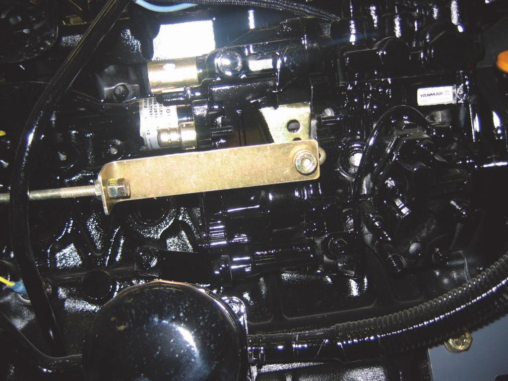

4.Loosen the jam nut on the throttle cable below the control handle and lift the cable our of the slot in the mainframe.

6.Loosen the jam nut securing the hand throttle cable to the tab welded to the engine mount weldment.
7.Remove the cable. If replacing the cable, remove the yokes, washers and jam nuts from the old cable.
8.Disconnect the ball joint on the ball stud securing the throttle control rod to the support bracket on the rear lower left side of the engine.
9.Remove the shoulder bolt and locknut securing the throttle rod support bracket to the fuel injector arm on the engine. Pull the throttle rod out the back of the loader.
Installation Procedure* - follow all warnings first, the reverse the removal steps.
* Perform the “Hand Throttle Adjustment” procedure found in this chapter after the installation is complete.
Foot Throttle and Foot Throttle Cable

Removal and Installation - Non-DPF Models
Removal Procedure - T-Bar Controls
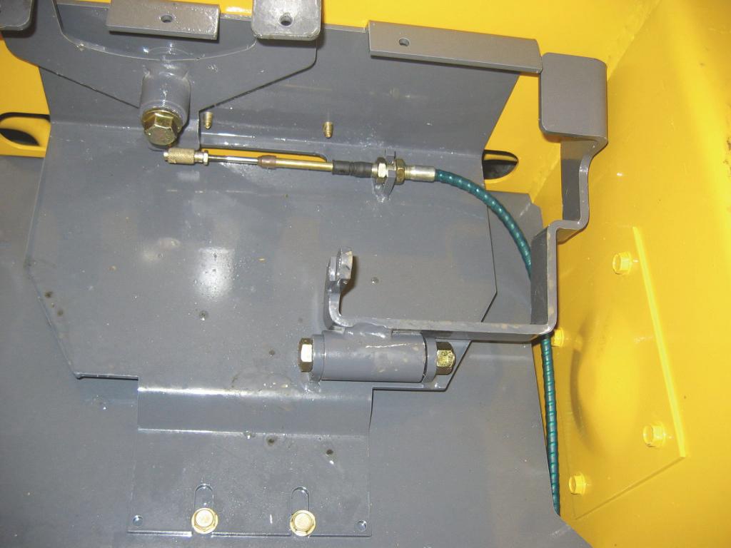
Warning
BEFORE beginning this service procedure, perform the following SAFETY procedures:
■ Remove attachment from lift arm.
■ Raise lift arm; engage lift arm support device.
■ Shut off the engine.
■ Tilt back ROPS/FOPS until lock engages. (For detailed instructions, refer to the Safety chapter of this manual.)
1.Remove the floor cover and kickplate per the procedure in the Mainframe chapter.
2.Remove the clevis pin and clip pin on the throttle cable yoke connected to the foot pedal assembly.
4.Remove the screw and locknut securing the foot pedal throttle to the auxiliary control mount weldment and remove the pedal.
5.Loosen the jam nut on the foot throttle cable securing the cable to the throttle tab. Slide the cable out of the tab.
6.At the engine cable mount weldment, disconnect the clevis pin and clip pin securing the yoke of the foot throttle cable to the foot throttle pivot.
3.Remove
7.Loosen the jam nut securing the foot throttle cable to the cable mount bracket and pull the cable out of the bracket.
8.Remove the cable. If replacing the cable, remove the yokes, washers and jam nuts from the old cable.
Installation Procedure* - follow all warnings first, the reverse the removal steps.
* Perform the “Foot Throttle Adjustment” procedure found in this chapter after the installation is complete.
Hand Throttle Adjustment - Non-DPF Models
The handle throttle is adjusted at the factory to provide a full range of engine speed adjustment, from IDLE to FULL throttle. If the hand throttle is replaced, it may be necessary to make the following adjustment.
Adjustment Procedure
The hand throttle can be adjusted at four different locations: (1) at the yoke attached to the throttle grip, (2) at the yoke on the throttle pivot, (3) at the ball joint end of the throttle rod, and (4) the clevis attached to the engine.
Warning
BEFORE beginning this service procedure, perform the following SAFETY procedures:
■ Remove attachment from lift arm.
■ Raise lift arm; engage lift arm support device.
■ Shut off the engine.
■ Tilt back ROPS/FOPS until lock engages. (For detailed instructions, refer to the Safety chapter of this manual.)
Important
DO NOT attempt to adjust the hand throttle lever at the two fuel injection pump adjustment screws.
1.Test the movement of the hand throttle to determine if the cable needs to be shortened or lengthened. When the hand throttle and the fuel injection pump are at the low idle position simultaneously, proper adjustment is achieved. BE SURE that the hand throttle lever does not interfere with the yoke attached to it.
2.If the cable needs adjustment, choose a location and: (1) loosen the jam nut on the yoke, clevis or ball joint, (2) remove the clevis pin and cotter pin on the yoke or the ball joint on the ball stud, (3) twist the yoke or ball joint to shorten or lengthen the throttle cable as needed, (4) reattach the yoke or ball joint.
3.Push and pull the hand throttle to check for correct operation. Repeat the adjustment steps as needed.
4.Tighten the jam nut against the yoke or ball joint to secure the adjustment.
Hand Throttle Tension Adjustment - NonDPF Models
Hand throttle tension should be tight enough to maintain the desired engine RPM, but loose enough to allow easy operation. The hand throttle tension can be INCREASED or DECREASED.
Adjustment Procedure
Warning
BEFORE beginning this service procedure, perform the following SAFETY procedures:
■ Shut off the engine.
(For detailed instructions, refer to the Safety chapter of this manual.)
NOTE: The spring washers and the friction washer must be installed properly to provide tension against the hand throttle.
1.To INCREASE TENSION, tighten the capscrew and locknut that attaches the hand throttle to the mainframe.
2.To DECREASE TENSION, loosen the capscrew and locknut that attaches the hand throttle to the mainframe.
Foot Throttle Adjustment - Non-DPF Models
Loaders with T-bar controls include a foot throttle to control the engine RPM, to match increased power requirements. The foot throttle is coupled to the hand throttle through a throttle rod pivot assembly. The foot throttle is at proper adjustment when pushing the hand throttle FULLY FORWARD causes the foot pedal to be pressed flush against the floor plate.
Adjustment Procedure - T-Bar Controls
Warning
BEFORE beginning this service procedure, perform the following SAFETY procedures:
■ Remove attachment from lift arm.
■ Raise lift arm; engage lift arm support device.
■ Shut off the engine.
■ Tilt back ROPS/FOPS until lock engages. (For detailed instructions, refer to the Safety chapter of this manual.)
1.Remove the floor cover and kickplate per the procedure in the Mainframe chapter.
2.With the hand throttle pulled back to the IDLE position, disconnect the clevis pin attaching the yoke on the foot pedal assembly.
3.Push down on the foot pedal until it is flush with the top of the auxiliary control mount weldment.
4.Loosen the jam nut on the yoke of the foot pedal assembly. Adjust the foot throttle cable after moving the hand throttle lever to its HIGH IDLE position. Retighten the jam nut on the yoke.
5.Start the engine and test the foot pedal throttle for full range of engine speed. Repeat the adjustment steps as needed.
Chapter Notes
Introduction
This chapter covers troubleshooting, testing, removal, installation, and adjustment procedures for the tandem pump system on Gehl R105 and Mustang 1050R model skid-steer loaders.
A hydrostatic pump assembly coupled to the engine provides power to two fixed-displacement hydrostatic drive motors. The motors drive the wheels on each side of the loader through a chain-and-sprocket system. The pumps and motors are controlled individually, allowing complete flexibility in forward, reverse, gradual, pivot and spin turns.
For detailed information on pump and motor internal repairs, consult the Gehl-Mustang Service Department or the component manufacturer’s service manual. Related hydraulic components are covered in the Hydraulic System chapter of this manual.
1FITTING/STRAIGHT
2FITTING/TEE
3FITTING/90°
4FITTING/STRAIGHT
5FITTING/STRAIGHT
Hydrostatic Controls
1BRACKET/NEUTRAL CENTERING
2PLATE/NEUTRAL ADJUST
3HUB/NEUTRAL SPRING MOUNT
4NUT/SERRATED LOCK
5NUT/LOCK
6SCREW/CAP
7NUT/SPIRALOCK
8ARM/PUMP
9ROD/CONTROL RIGHT
10ROD/CONTROL LEFT
11ASSY/CENTERING BRACKET
12TURNBUCKLE
13RETAINER/PUMP ARM
14NUT/LOCK FLANGE CENTERLOCK
15NUT/HEX
16SCREW/CAP WHIZLOCK
17SPRING/TORSION
18ROD END/FEMALE
19SCREW/CAP
20NUT/HEX
21BOLT/CARRIAGE
22SCREW/CAP
23SCREW/CAP
24WASHER/FLAT
Charge Pressure Test and Adjustment
Gehl R105 and Mustang 1050R model skid-steer loaders have, as standard equipment, a charge pressure test port as part of the hydrostatic pump system. Before performing the following test, run the skid-steer loader to be sure the hydraulic oil is at normal operating temperature.
NOTE: This test requires a minimum of a 500 psi (34.5 bar) pressure gauge.
Warning
BEFORE beginning this service procedure, perform the following SAFETY procedures:
■ Shut off the engine.
■ Raise and block the loader so that all four tires are off the ground.
■ Tilt back ROPS/FOPS until lock engages. (For detailed instructions, refer to the Safety chapter of this manual.)
Test Procedure
1.Using an Allen wrench, remove the plug and install the pressure gauge on the brake valve charge pressure port.
2.Start the engine ensuring that the brake switch on the instrument panel shows the parking brakes locked.
3.Check pressure reading on the gauge under three different conditions: (1) with the steering controls in NEUTRAL, (2) both pumps stroked forward and backward, and (3) when stroking each pump individually. The gauge should read as follows: 130150 psi (9-10 bar). Minimum pressure should be: 100 psi (7 bar).


4.A slight drop in pressure is normal when a load is put on the hydrostatic pump. If the pressure reading on the gauge is either lower or higher than specified, refer to the manufacturer’s service manual for the hydrostatic pump, and the charge pressure adjustment procedure that follows.
Adjustment Procedure
Add or remove shims on the charge pressure relief valve (next section) to adjust the charge pressure. Add shims to increase the charge pressure; remove shims to decrease the charge pressure.
Hydrostatic Pump Relief Valves
Each hydrostatic pump is equipped with two highpressure relief valves, for a total of four hydrostatic pump relief valves in the hydrostatic drive system. The two front relief valves on the hydrostatic pump assembly control the front hydrostatic pump, which drives the left side of the skid loader. The two rear relief valves on the hydrostatic pump assembly control the rear hydrostatic pump, which drives the right side of the skid-steer loader. Refer to the manufacturer’s manual for service procedures.
Hydrostatic Pump Removal / Installation
Warning
BEFORE beginning this service procedure, perform the following SAFETY procedures:
■ Remove attachment from lift arm.
■ Raise lift arm; engage lift arm support device.
■ Shut off the engine.
■ Tilt back ROPS/FOPS until lock engages. (For detailed instructions, refer to the Safety chapter of this service manual.)
Removal Procedure
1.Remove the pressure cap from the hydraulic reservoir to relieve any pressure.
2.Drain the oil from the hydraulic reservoir per the procedure in the Lubrication chapter.
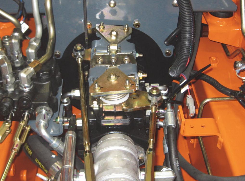
Important
Drive Motor Hot-Oil Shuttle Valve
The hot-oil shuttle valve is a spring-loaded spool valve located in the end cover of each drive motor. The purpose of the shuttle is to allow a small portion of the closed-loop circuit oil back to the hydraulic reservoir for cooling and filtering (this is referred to as “case drain” oil).
Cooling oil must be taken from the low-pressure side of the closed-loop circuit. This is necessary to prevent loss of drive power. Because the drive motor are reversible, neither of the ports are continuously high or low pressure, depending on the direction of travel.
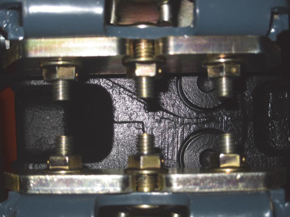
The spool valve senses pressure differentials and moves to block the high-pressure port and open the lowpressure side to the hydraulic reservoir. When the loader is in NEUTRAL, the spool is in a center position. There is another shuttle relief valve in the case drain line to control the amount of oil flow and to maintain pressure in the drive motor circuit. It is necessary to remove the drive motors to service this shuttle. Refer to the manufacturer’s manual for service procedures.
Mark the hoses, tubes and fittings for reassembly, and cap or plug them after they are disconnected to prevent contaminants from entering the hydraulic system.
3.Disconnect the hydrostatic pump are control rods from the neutral centering devices.
4.Disconnect three hydraulic pressure hoses at the gear pump.

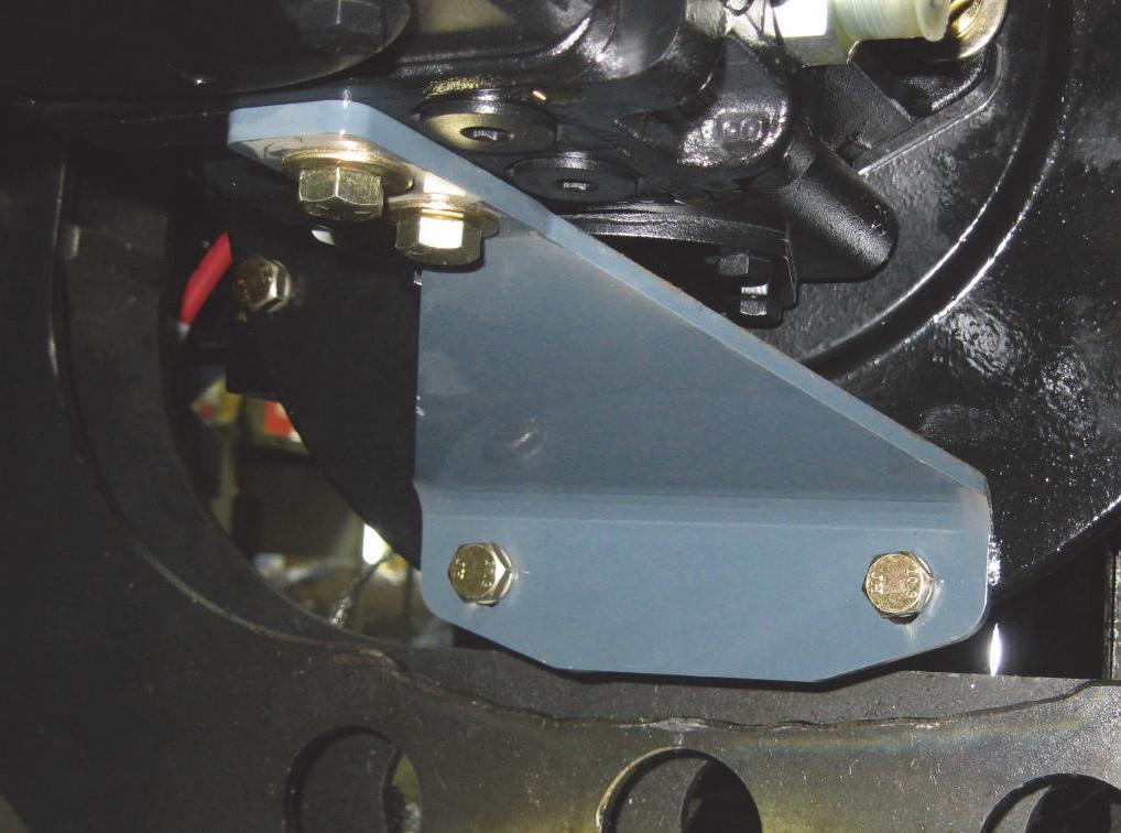
8.Remove two screws (35 ft-lbs) (48 N•m) connecting the pump support to the pump flange.
5.Support the gear pump. Remove two screws and washers securing the gear pump to the hydrostatic pump. Pull the gear pump forward and up, out of the chassis.
6.Label and disconnect all the hydraulic hoses connected to the hydrostatic pump.

9.Remove the two screws (80 ft-lbs.) (112 N•m) securing the hydrostatic pump to the flywheel housing cover. Lift the pump slightly to remove the screws.
7.Position a suitable hoist of adequate capacity and a positive locking mechanism able to support the hydrostatic pump. Attach lifting straps around the pump and raise the hoist to remove slack from the strap/hook. The hoist should now support the weight of the pump.
10.Shift the hydrostatic pump forward to disengage the splined shaft drive of the pump and pull the pump out of the flywheel.

11.Lift and maneuver the hydrostatic pump out of the skid-steer loader.
Installation Procedure* - Follow all warnings first, then reverse the removal steps.
* Coat pump shaft splines (male and female) with molybdenumdisulfide (“moly”) grease.
Hydrostatic Pump Flexible Drive Coupling Removal and Installation
Removal Procedure
Warning
BEFORE beginning this service procedure, perform the following SAFETY procedures:
■ Remove attachment from lift arm.
■ Raise lift arm, engage lift arm support device.
■ Shut off the engine.
■ Tilt back ROPS/FOPS until lock engages. (For detailed instructions, refer to the Safety chapter of this manual.)
1.Remove the hydrostatic pump per the procedure in this chapter.
2.Remove two screws (50 ft-lbs.) (70 N•m) and washers securing the pump support to the flywheel housing cover.


3.Remove three carriage bolts (80 ft-lbs.) (112 N•m) and locknuts securing the top of the engine mount weldment to the engine cross-angle brace.


* Regrease the tooth spline of the flexible drive coupling plate before reinstalling the hydrostatic pump.
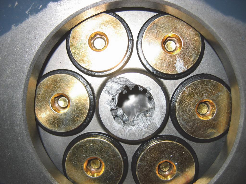
Drive Motor Removal and Installation
Warning
BEFORE beginning this service procedure, perform the following SAFETY procedures:
■ Remove attachment from lift arm.
■ Raise lift arm; engage lift arm support device.
■ Shut off the engine.
■ Tilt back ROPS/FOPS until lock engages.
■ Raise and securely block the loader so all four tires are off the ground.
(For detailed instructions, refer to the Safety chapter of this manual.)
Removal Procedure
1.Underneath the skid-steer loader, remove the screws securing the front belly pan and then remove the belly pan from the chassis.
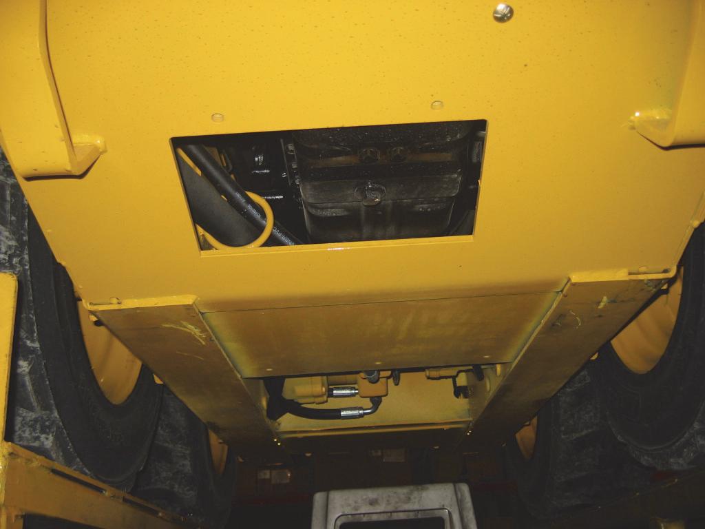
2.Remove drive chains per the procedure in the Wheel Drives chapter.
3.If necessary, drain oil from hydraulic reservoir per the procedure in the Hydraulic System chapter.
NOTE: If the hydraulic hoses and tubes are plugged after removal to prevent oil leakage, it should not be necessary to drain the hydraulic reservoir. Hydraulic hoses and tubes should be plugged to prevent contaminants from entering the hydraulic system.
4.BEFORE disconnecting hydraulic hoses and tubes from the drive motor, mark each hose/tube and the port where it attaches to the drive motor (so that hoses/tubes can be correctly re-attached during installation).
5.Disconnect all hydraulic hoses and tubes on each drive motor.

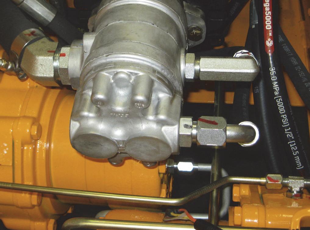

6.Remove screws (120 ft-lbs.) (168 N•m) (Loctite 242) and seal washers attaching the drive motor to the chaincase. Lower the drive motor and o-ring seal through the belly pan with a suitable hoist of adequate capacity and a positive locking mechanism to support the drive motor.
Installation Procedure - Follow all warnings first, then reverse the removal steps.
NOTE: Install o-ring seal on the drive motor. Scrape off old gasket material and apply new sealant to mating surface of the drive motor before reassembly to the chassis. Perform the drive chain adjustment procedure in the Wheel Drives chapter after reinstallation of the drive chains.


Troubleshooting Guide
The troubleshooting guide lists potential hydrostatic system problems, as well as possible causes and remedies.
If you cannot locate a particular hydrostatic system problem in this chart, consult the troubleshooting chart in the Hydraulic System chapter.
When a problem occurs, don’t overlook simple causes. A malfunction could be caused by something as simple as low fluid level in the hydraulic reservoir. After a mechanical failure has been corrected, be sure to locate the cause of the problem.
ProblemPossible CauseRemedy
Noresponsefromthehydrostaticdrive orthelift/tiltsystems
Hydraulicoilviscositytoohigh
Hydraulicoilsupplytoolow
Hydrostaticpumpdrivedisconnected Drivecouplingfailure.
Tractiondrivewillnotoperateineither direction Parkingbrakeengaged.
Hydraulicoilsupplytoolow
Controlrodlinkagedisconnected
Allowlongerwarm-uporreplaceoil withtheproperviscosityoil.
Checkforlowoillevelinreservoir.Add oilasneeded.
Checkforbrokenorwornpumpdrive couplingandreplace,asneeded.
Disengageparkingbrake.
Checkforlowoillevelinreservoir.Add oilifnecessary.
Checklinkageconnectionatcontrol leversandneutralcenteringmechanisms.Reconnectlinkage.
Drivewheelsdonotturninproper directionforT-Barmovement
Lowornochargepressure
Hydrostaticpumpreliefvalvesmalfunctioning
Highpressurehydraulichoses betweenhydrostaticpumpanddrive motorsconnectedincorrectly
Lift/tiltcontrolsfailtorespondHydraulicoilviscositytoohigh
Hydraulicoillevellow
Solenoidvalve(s)malfunctioning
Restraintbarorseatswitchmalfunction
Seehydrostaticpumpmanual.
Inspectandcleanthereliefvalves. Replacethemasneeded.
Reconnecthosestoproperportson thedrivemotors.Refertoschematic andfiguresinthe Hydrostatic System chapter.
Allowlongerwarm-uporreplacewith theproperviscosityoil.
Checkoillevelinreservoir.Ifoilislow, checkforanexternalleak.Repairand addoil.
Checkelectricalconnectionstolift/tilt solenoidsandrepair.
Checkswitches.
ProblemPossible CauseRemedy
NeutraldifficulttomaintainRodendslooseoncenteringmechanismorservorod
Neutralcenteringmechanism(s)outof adjustment
Clampingboltloose Hydrostaticpumpoutofadjustment
SluggishaccelerationAirinthehydraulicsystem
Checkandtightenorreplacecomponents.
Adjustneutralcenteringmechanism(s). See Controls chapterforprocedure.
Tightenclampbolt.
Seehydrostaticpumpmanual.
Cycletheliftandtiltcylinderstomaximumstrokeandmaintainpressurefor ashorttimetoclearairfromsystem. Checkhydraulicoilreservoir;fillas needed.
Hydraulicoilsupplytoolow
Lowhydrostaticsystemchargepressure
Drivemotor(s)orhydrostaticpump(s) haveinternaldamageorleakage
Enginenotrespondingunderload
Automaticparkingbrakepartially engaged
HydrostaticdriveoverheatingDrivesystemoverloadedcontinuously
Lift,tiltorauxiliarysystemoverloaded continuously
Drivemotor(s)orhydrostaticpump(s) haveinternaldamageorleakage
Oilcoolerpluggedwithdebris
Loaderbeingoperatedinahightemperatureareawithnoaircirculation
Checkhydraulicoilreservoir.Addoil,if necessary.
Seehydrostaticpumpmanual.
Refertocomponentmanufacturer’s servicemanual.
Troubleshootengine.
Contactyourdealer.
Improveefficiencyofoperation.
Improveefficiencyofoperation.
Refertocomponentmanufacturer’s servicemanual.
Cleanoilcoolerfins.
Reducedutycycleandimproveaircirculation.
ProblemPossible CauseRemedy
Hydrostatic(drive)systemnoisyHydraulicoilviscositytoohigh
Drivemotor(s)orhydrostaticpump(s) haveinternaldamageorleakage Airinhydraulicsystem.
Allowlongerwarm-uporreplaceoil withtheproperviscosityoil.
Refertocomponentmanufacturer’s servicemanual.
Cycleliftandtiltcylinderstomaximum strokeandmaintainpressurefora shorttimetoclearairfromsystem. Checkoillevelinreservoir;fillas needed.
Rightsidedoesn’tdriveineitherdirection.Leftsideoperatesnormally
Excessiveinternalleakageinright drivemotor
Repairorreplaceasneeded.Referto motormanufacturer’sservicemanual.
Excessiveleakageinengine-end hydrostaticpump
Servocontrollermalfunctioning
Reliefvalvesonengine-endhydrostatic pumpmalfunctioning Controlrodlinkagetoengine-end hydrostaticservoisdisconnected
Keymissingonrearpumparmcontrol shaft.
Rightsidedoesn’tdriveinonedirectionReliefvalveonengine-endhydrostatic pumpmalfunctioning
Refertothepumpmanufacturer’smanualforserviceprocedures.Repairor replacerearpumpasneeded.
Refertothepumpmanufacturer’smanualforserviceprocedures.Repairor replacerearpumpasneeded.
Switchvalveswiththoseonfront hydrostaticpump.See“Hydrostatic PumpReliefValves”informationinthis chapter;problemshouldswitchtothe leftside.Replacedefectivereliefvalve. Reattachcontrolrodlinkage.
Replacethekey.Torquescrewonthe armto30fit-lbs.(40N•m).
Switchonereliefvalvewiththeother reliefvalveonrearpump;problem shouldswitchtoreversedirection. Cleanorreplacethefaultyvalveas needed.
Engine-endhydrostaticpumpmalfunctioning
Servocontrollermalfunctioning
Refertopumpmanufacturer’smanual forserviceprocedures.Repairor replacerearpumpasneeded.
Refertopumpmanufacturer’smanual forserviceprocedures.Repairor replacerearpumpasneeded.
ProblemPossible CauseRemedy
Leftsidedoesn’tdriveineitherdirection.Rightsideoperatesnormally
Excessiveinternalleakageinleftdrive motor
Excessiveleakageingear-endhydrostaticpump
Reliefvalvesongear-endhydrostatic pumpmalfunctioning
Repairorreplaceasneeded.Referto motormanufacturer’sservicemanual.
Refertopumpmanufacturer’smanual forserviceprocedures.Repairor replacethefrontpumpasneeded.
Switchvalveswiththoseonrearhydrostaticpump.See“HydrostaticPump ReliefValves”informationinthischapter;problemshouldswitchtotheright side.Replacedefectivereliefvalveas needed.
Servocontrollermalfunctioning
Controlrodlinkagetogear-endhydrostaticservodisconnected
Keymissingonfrontpumparmcontrol shaft.
Leftsidedoesn’tdriveinonedirectionReliefvalveongear-endhydrostatic pumpmalfunctioning
Refertothepumpmanufacturer’smanualforserviceprocedures.Repairor replacerearpumpasneeded.
Reattachcontrolrodlinkage.
Replacethekey.Torquescrewonthe armto30fit-lbs.(40N•m).
Switchreliefvalvewithotherrelief valveonfrontpump;problemshould switchtothereversedirection.Clean orreplacethefaultyvalveasneeded.
Gear-endhydrostaticpumpmalfunctioning
Servocontrollermalfunctioning
Refertopumpmanufacturer’smanual forserviceprocedures.Repairor replacefrontpumpasneeded.
Refertopumpmanufacturer’smanual forserviceprocedures.Repairor replacefrontpumpasneeded.
Hydrostatic/Hydraulic Schematic - Gehl R105
Hydrostatic/Hydraulic Schematic - Mustang 1050R
Introduction
This chapter covers troubleshooting, testing, removal, installation and adjustment procedures for hydraulic system components on Gehl R105 and Mustang 1050R model skid-steer loaders. Primary hydraulic system components in this chapter are shown below and on following pages.
Power for the lift arm functions and auxiliary hydraulics is provided by a gear pump attached to the front of the tandem pumps.
Models include a standard-flow auxiliary hydraulics system with two hydraulic couplers on the left lift arm for attachment hookup.
Information on recommended hydraulic fluids, capacities and filter change intervals is in the Lubrication chapter. For detailed information on gear pump or control valve internal repair, consult the GehlMustang Service Department and/or the hydraulic component manufacturer’s service manual. Hydraulic components related to the drive system are covered in the Hydrostatic System chapter.
When a problem occurs, don’t overlook simple causes. A malfunction could be caused by something as simple as low fluid level in the hydraulic reservoir. After a mechanical failure has been corrected, be sure to locate the cause of the problem.
Hydraulics - Lift Arm Components
1BRACKET/COUPLER RETAINER
2FITTING/STRAIGHT
3FITTING/90
4SCREW/CAP LOCKING
5FITTING/TEE
6FITTING/90
7NUT/LOCK
8FITTING/90
9FITTING/45
10COUPLER/HYDRAULIC
11COUPLER/HYDRAULIC
12TIE/CABLE
13CYLINDER/LIFT
14HYDRAULIC LINE/OUTER
15HYDRAULIC LINE/INNER
16HOSE/HYDRAULIC
17ASSY/HOSE AND TUBE
18ASSY/HYDRAULIC HOSE
19HYDRAULIC LINE/LIFT CYLINDER
20ASSY/HYDRAULIC LINE
21ASSY/HYDRAULIC LINE
22ASSY/HYDRAULIC HOSE
23CLAMP/HOSE
30PIN/PIVOT TILT CYLINDER
31SCREW/CAP
32SEAL
33RING/SNAP
34CLIP/HYDRAULIC LINE
35CLIP/HYDRAULIC LINE
36WASHER/SPECIAL
37WASHER/SPECIAL
38WASHER/SPECIAL
39FITTING/STRAIGHT
40FITTING/90
41SCREWCAP
42SCREW/CAP
Hydraulics - Chassis Components - DPF Models
46 36
AUXILIARY CIRCUIT
1ELBOW 90
2CLAMP/HOSE 3ELBOW/SWIVEL
4FITTING/90
5Elbow/90
34 38
47
24 4 26
13 RETURN TO TANK THROUGH COOLER TO GEAR PUMP 7 7
40 35
3
30
12 26
33
9 37 37 36
18OIL TEMP SWITCH
20FITTING/TEE RUN
23 23 45
2 31
36 36 44 LIFT CIRCUIT TILT CIRCUIT
28FITTING/TEE RUN
29TUBE/VALVE TO LIFT/LEFT
30VALVE/CONTROL 31FITTING/TEE
47 36
15
10 22 19
39TUBE/AUXILIARY/LOWER 40TUBE/TILT LOWER 18 48 17 25
RETURN 11
24 4 29
20
21 46 36
14 43
45 6
41 38 39 6 6 4 16
37CLIP/HYD LINE 21 7 37 1 27 5
28
42 13 11
FILTER TO TANK
Hydraulics - Chassis Components - Non-DPF Models
1ELBOW 90
2CLAMP/HOSE
3ELBOW/SWIVEL
4FITTING/90
5Elbow/90
6FITTING/ST
7FITTING/ST
8FITTING/TEE RUN
9CLAMP/HOSE
10BHSCS
11CAP
12PLATE/TOP TWIN
13CLAMP/TUBE
14HFS
15UNION/HYDRAULIC
16OIL TEMP SWITCH
17FITTING/90
18FITTING/TEE
19FILTER ASSEMBLY
20FITTING/ST
21NUT/SPIRALOCK
22STRAP
23VALVE PACKAGE
24VALVE/SOLENOID
25TUBE/TANK-BRAKE
26FITTING/TEE RUN
27TUBE/VALVE TO LIFT
28VALVE/CONTROL
29FITTING/TEE
30TUBE/VALVE TO LIFT 31TUBE/LIFT
32TUBE/TILT UPPER 33TUBE/TANK RETURN 34NUT/FLRSUF
LINE
Pressure Tests, Control Valve
The control valve on the skid-steer loader controls lift and tilt functions of the lift arm and standard auxiliary hydraulics. It is located on the right side of the chassis. The relief valve in the control valve can be tested at the lift arm couplers.
Test Procedure
Warning
BEFORE beginning this service procedure, perform the following SAFETY procedures:
■ Shut off the engine.
■ Relieve hydraulic system pressure.
(For detailed instructions, refer to the Safety chapter of this manual.)
NOTE: To prevent contamination, ALWAYS clean the area around hydraulic fittings before disconnecting any hydraulic plug, hose or tube.

1.What you’ll need: an assistant and a minimum 5000 psi (345 bar) pressure gauge.
2.Perform the pressure tests at the auxiliary hydraulic couplers located on the left lift arm.
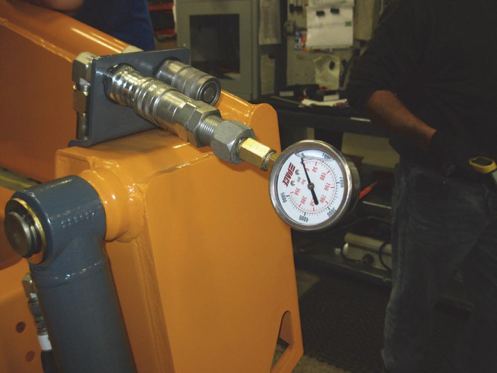
Warning
BEFORE continuing this service procedure, perform the following SAFETY procedures: a. Standard auxiliary relief valve can be found at the front of the control valve.
■ Shut off the engine.
■ Tilt back ROPS/FOPS until lock engages. (For detailed instructions, refer to the Safety chapter in this manual.)
3.Install the pressure gauge in the end of the male coupler and activate the auxiliary hydraulic circuit to pressurize the line.
4.For this test, engine should be at HIGH IDLE.
5.Have assistant observe the pressure reading on the gauge. The pressure reading on the loader should be at least 2750 psi (190 bar).
6.If the pressure reading is NOT at the specified pressure, adjust pressure as follows: b. With an Allen wrench, turn the adjuster screw IN to increase pressure or OUT to decrease pressure.
Tilt Cylinder Test
If the bucket (or attachment) drifts down with the tilt control in the NEUTRAL position, first check the tilt cylinders for external leakage. If external leakage is evident, a new seal kit should be installed in the leaking cylinder(s). If no external leakage is evident, check the tilt cylinders for internal leakage according to the following procedure.
NOTE: When checking for drifting, the ignition key MUST BE in the OFF position, operator in the seat, and the restraint bar lowered. The maximum allowable tilt cylinder circuit drifting with a loaded bucket is 0.88" (22 mm) of cylinder extension in 15 minutes.
Test Procedure
c. Repeat steps 4 and 5.
d. After the pressure is within the correct PSI range, tighten the locknut on the control valve adjuster screw to secure the adjustment.
7.If, after the adjustment, there is NO CHANGE in the pressure reading, this indicates either a defective hydraulic gear pump or relief valve cartridge (on the control valve). To determine which is the cause, first replace the relief valve cartridge. If the pressure reading still does not change, the hydraulic gear pump should be repaired or replaced.
Warning
BEFORE beginning this service procedure, perform the following SAFETY procedures:
■ Shut off the engine.
■ Relieve hydraulic system pressure. (For detailed instructions, refer to the Safety chapter of this manual.)

1.Load the bucket and allow it to rest on the ground.
NOTE: To prevent contamination, ALWAYS clean the area around hydraulic fittings before disconnecting any hydraulic hose or tube.
2.Checking the right tilt cylinder: Remove the lower hydraulic hose from the right tilt cylinder and cap or plug the hose and cylinder port. Caps or plugs MUST BE able to withstand full hydraulic pressure.

3.Crack open (slightly loosen) the upper hydraulic hose on the right tilt cylinder.
Warning
BEFORE raising a loaded bucket, BE SURE no personnel are near the loader. Serious personal injury can result if bucket drops suddenly or its contents spill out.
4.Climb back into the operator’s seat, lower the restraint bar, and start the engine.
5.Raise the lift arm enough for the bucket (or attachment) to clear the ground.
6.Shut off the engine, turn the ignition key to the ON position (engine OFF) and operate the tilt control in both directions.
7.If the bucket drifts, the blocked tilt cylinder has leaking piston seals. If it DOES NOT drift, lower the lift arm and reconnect/retighten the hydraulic hose(s) to the cylinder.
8.Checking the left tilt cylinder: Remove the lower hydraulic hoses on the left tilt cylinder and cap or plug the cylinder ports. Caps or plugs MUST BE able to withstand full hydraulic pressure.
9.Connect the two hoses, just removed, together with a straight fitting.
10.Crack open (slightly loosen) the inside upper hydraulic hose on the left tilt cylinder.
11.Repeat steps 4 - 7 for the left tilt cylinder.
12.After both tilt cylinders have been tested, be sure the hydraulic hoses are reconnected or retightened.
NOTE: If both tilt cylinders have good seals, and the bucket still drifts, the fault could be in either the control valve or the self-leveling valve. Continue the test procedure with step 13, below. Also, refer to the Troubleshooting Guide in this chapter.
13.To determine if either the control valve or self-leveling valve is faulty and causing the bucket to drift, perform the “Self-Leveling Valve Test” procedure in this chapter.
Self-Leveling Valve Test
Test Procedure
Warning
BEFORE beginning this service procedure, perform the following SAFETY procedures:
■ Shut off the engine.
(For detailed instructions, refer to the Safety chapter in this manual.)
1.Open the engine access cover and lock open the rear grille.
2.Loosen the jam nut on the self-leveling valve adjuster screw.
Lift Cylinder Test
If the lift arm drifts with the lift control in NEUTRAL position, and the ignition key OFF, first check the lift cylinders for external leakage. If external leakage is evident, a new seal kit should be installed in the leaking cylinder(s). If no external leakage is evident, check the lift cylinders for internal leakage according to the following procedure.
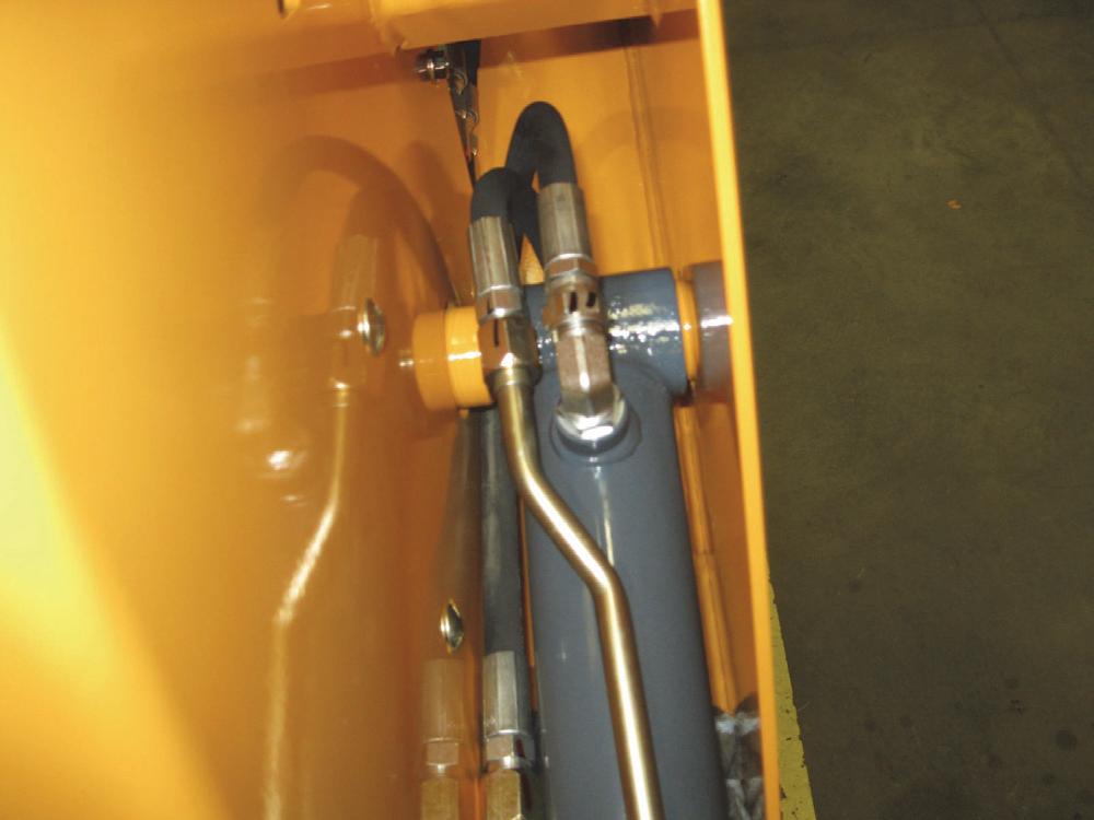
NOTE: When checking lift arm for drifting, BE SURE the ignition key is in the OFF position. The maximum allowable lift cylinder drifting is 0.75" (19 mm) of cylinder retraction in 15 minutes.

Test Procedure
1.Remove the bucket or attachment from the attachment bracket.
2.Raise the lift arm to maximum height. Then release the lift cylinder lift arm support device and slowly lower the lift arm to engage the device.
Warning
BEFORE continuing this service procedure, perform the following SAFETY procedures:
■ Shut off the engine.
■ Relieve hydraulic system pressure.
(For detailed instructions, refer to the Safety chapter in this manual.)
NOTE: For step 3, BE SURE to count and record the number of turns, so the adjuster screw can be returned to its original setting after the test.
3.With an Allen wrench, turn the adjuster screw in (clockwise) until it bottoms out. The self-leveling valve is now disabled and will not affect the tilt operations.
4.Perform steps 4 - 7 of the “Tilt Cylinder Test” procedure. If the bucket no longer drifts, the self-leveling valve is defective. If the bucket continues to drift, the control valve is defective and in need of repair or replacement.
5.Refer to the “Self-Leveling Valve Adjustment” procedure in this chapter for correct adjustment of the self-leveling valve.
3.Remove the clamp securing the hydraulic tubes to the lift cylinder on the side being tested.
NOTE: To prevent contamination, ALWAYS clean around hydraulic fittings before disconnecting any hydraulic lines.
4.Disconnect the hydraulic tube from the rod end port of the lift cylinder to be tested.
Solenoid Valve Test - Tilt, Lift, Brake
During normal operations, the solenoid valves should prevent operation of the lift arm and drive functions if any of the safety interlock system switches are open, for example:
» Operator not sitting on the seat.
» Restraint bar not lowered.
Test Procedure
1.Climb into the operator’s seat, lower the restraint bar and start the engine.
2.Using the lift control, raise the lift arm off the ground enough so that the attachment can be tilted.
5.Install a plug on hydraulic tube. Attach a hose to rod end port of the cylinder and run the other end of the hose into a suitable container. Lower the ROPS.
6.Climb back into the operator’s seat, lower the restraint bar and start the engine.
7.Hold the lift control in the RAISE position. If the seals in the cylinder are defective and leaking, oil will flow out of the rod-end port.
8.Lower the lift arm support device back against the lift cylinder. Shut off the engine and move the lift control in both directions to relieve hydraulic pressure.
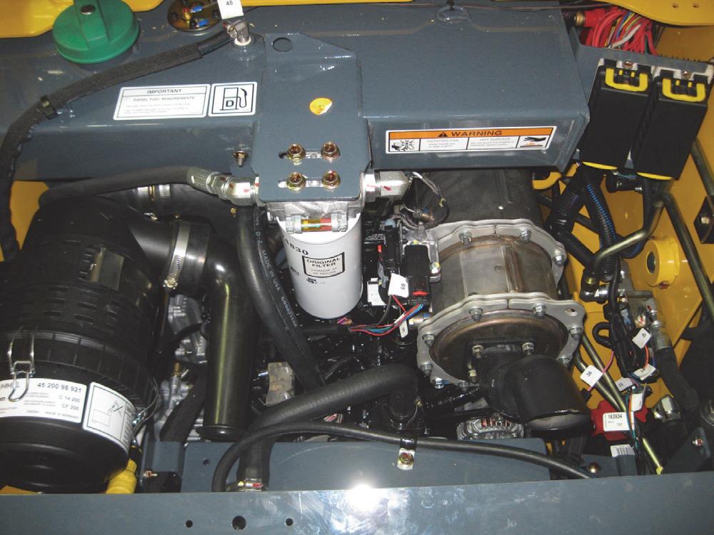
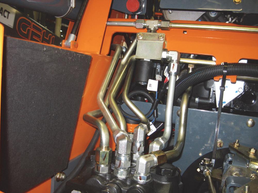
9.Reconnect the hydraulic tube to the cylinder, then reattach the clamp around the hydraulic tubes and cylinder.
NOTE: If neither lift cylinder shows signs of external or internal leakage, and the lift arm still drifts, the problem could be due to leaking hydraulic hose fittings between the control valve and the lift cylinders. Check all hydraulic hose fittings thoroughly. The fault could also be in either the control valve or the self-leveling valve. Continue the test procedure with step 11. Also refer to the Troubleshooting Guide in this chapter.
10.The other cylinder can be checked the same way.
11.To determine if either the control valve or the selfleveling valve is faulty, perform the “Self-Leveling Valve Test” procedure in this chapter.
3.Raise the restraint bar, use the lift and tilt controls (one at a time) to see if either function will operate.
» If the lift arm can be raised or lowered, the lift solenoid is malfunctioning.
» If the attachment can be tilted, the tilt solenoid is malfunctioning.

4.Lower the restraint bar. BE SURE the parking brake on the instrument panel is in the OFF position.
5.Raise the restraint bar. Use the drive controls (one at a time) to see if the tires will move.
» If the skid loader moves forward or backward, the brake solenoid is malfunctioning.
Hydraulic Oil Filter Element Replacement
Gehl R105 and Mustang 1050R model skid-steer loaders have one hydraulic oil filter. The hydraulic oil filter element should be replaced after every 250 hours of operation or annually (whichever occurs first).

NOTE: There is an initial 50-hour element replacement schedule for new skid-steer loaders with original filters.
6.If any solenoid in the above tests appears to be malfunctioning, test that solenoid coil as follows:


Warning
BEFORE continuing this service procedure, perform the following SAFETY procedure:
■ Remove attachment from lift arm.
■ Raise lift arm; engage lift arm support device.
(For detailed instructions, refer to the Safety chapter of this manual.)
» Have an assistant sit in the operator’s seat, lower the restraint bar and turn the keyswitch to ON. DO NOT start the engine.
» Using a thin strip of steel (such as a pocket ruler), check the suspected solenoid by moving the steel strip close to the solenoid coil.
» If the steel strip is magnetically attracted to the solenoid coil, the coil works and the solenoid cartridge may be causing the malfunction.
7.For service procedures, refer to “Solenoid Valve Removal and Installation/Disassembly and Reassembly” procedure in this chapter.
Replacement Procedure
Warning
BEFORE beginning this service procedure, perform the following SAFETY procedure:
■ Shut off the engine.
(For detailed instructions, refer to the Safety chapter in this manual.)
1.Open the engine access cover and lock open the rear grille.
2.Using a filter wrench, turn the filter element counterclockwise to remove it from the filter head.
3.Install the filter element. Before installation, apply a light coat of oil to the gasket, and then install it on the filter head.
4.Hand-tighten element until the gasket contacts the filter head. Turn element another 3/4 turn to seat the gasket.
5.Refer to the Lubrication chapter in this manual for the hydraulic fluid requirements and specifications.
Warning
NEVER use your hands to search for hydraulic fluid leaks. Use a piece of cardboard or paper. Escaping fluid under pressure can be invisible and penetrate the skin causing serious injury. If any fluid is injected into your skin, see a doctor at once. Injected fluid MUST be surgically removed by a doctor familiar with this type of injury or gangrene may result.
Warning
ALWAYS wear safety glasses when checking for hydraulic fluid leaks. Escaping fluid under pressure can be invisible and can cause permanent eyesight damage if safety glasses are not worn.
6.ALWAYS check for hydraulic fluid leaks after reassembling components of the hydraulic system.
Hydraulics - Auxiliary
Tilt Cylinder Removal and Installation

Removal Procedure
NOTE: Refer to the “Lift Arm Removal and Installation” procedure in the Mainframe chapter for instructions on removing the complete lift arm group, including the tilt cylinders.
1.Remove the bucket or attachment.
2.With the engine running, lower the lift arm until it is in contact (or near contact) with the lift arm stops (on front of chassis).
Warning
BEFORE continuing this service procedure, perform the following SAFETY procedures: the pin free of the taper. Remove the capscrew and washer. Remove the upper tilt cylinder pin while supporting the tilt cylinder and remove the tilt cylinder. tor at once. Injected fluid MUST be surgically removed by a doctor familiar with this type of injury or gangrene may result.
■ Shut off the engine.
■ Relieve hydraulic system pressure.
(For detailed instructions, refer to the Safety chapter in this manual.)
3.Position a suitable hoist of adequate capacity and a positive locking mechanism able to support the attachment bracket (hitch).
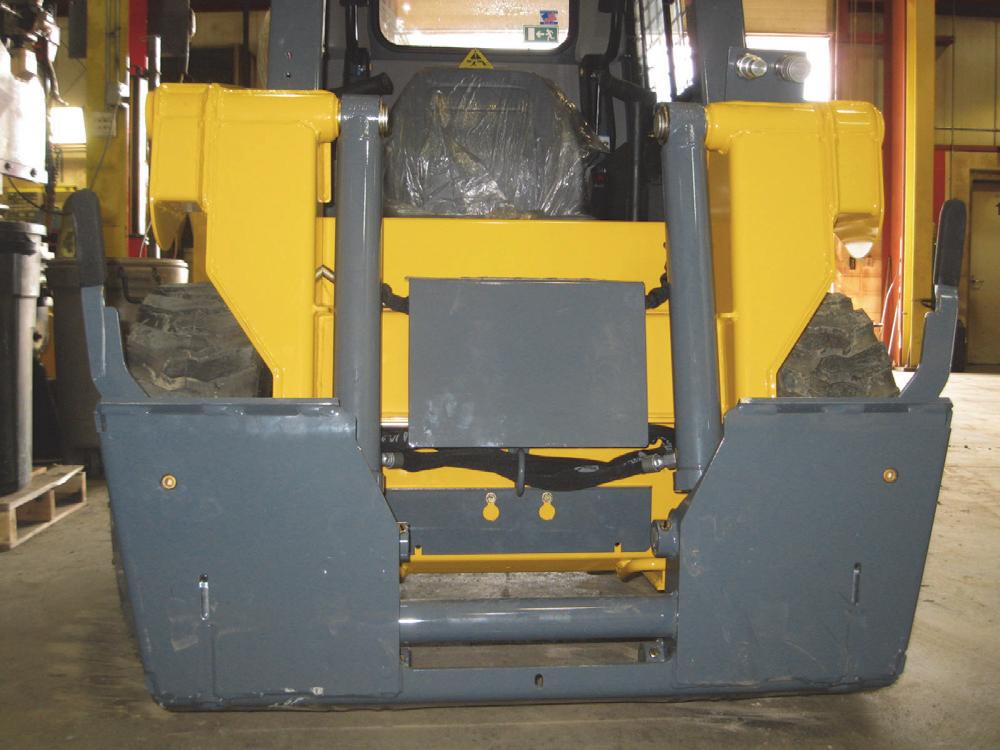
4.Disconnect the upper and lower tilt cylinder hoses from the cylinder ports. BE SURE to install plugs in the hoses and cap the fittings to prevent fluid loss and contamination of the hydraulic system.
5.While supporting the weight of the tilt cylinder, remove the capscrew and locknut securing the lower tilt cylinder pivot pin. Then drive the pivot pin out to release the lower end of the tilt cylinder.


Warning
ALWAYS wear safety glasses when checking for hydraulic fluid leaks. Escaping fluid under pressure can be invisible and can cause permanent eyesight damage if safety glasses are not worn.
4.ALWAYS check for hydraulic fluid leaks after reassembling components of the hydraulic system.
8.Using a punch, remove the upper tilt cylinder pins and remove the cylinders.
Installation Procedure
1.Install the upper end of the tilt cylinder in position on the lift arm and insert the pivot pin. Use Loctite® 242 or equivalent on the capscrew before reinstalling and torque to 80 ft.-lbs. (108 N•m). Secure the pivot pin with its snap ring.
2.Position the lower end of the tilt cylinder and insert the pivot pin through the cylinder and attachment mount. Secure the pivot pin with a capscrew and locknut.
NOTE: The grease fitting on the base and rod end of the tilt cylinder should face inward as installed.

3.Remove plugs/caps and attach the upper and lower tilt cylinder hoses to the cylinder.
NOTE: After removing/replacing any component in the hydraulic system, ALWAYS check the level of hydraulic fluid in the reservoir. Add fluid if necessary. Refer to the Lubrication chapter in this manual for the hydraulic fluid requirements and specifications.
Warning
NEVER use your hands to search for hydraulic fluid leaks. Use a piece of cardboard or paper. Escaping fluid under pressure can be invisible and penetrate the skin causing serious injury. If any fluid is injected into your skin, see a doc-
Lift Cylinder Components
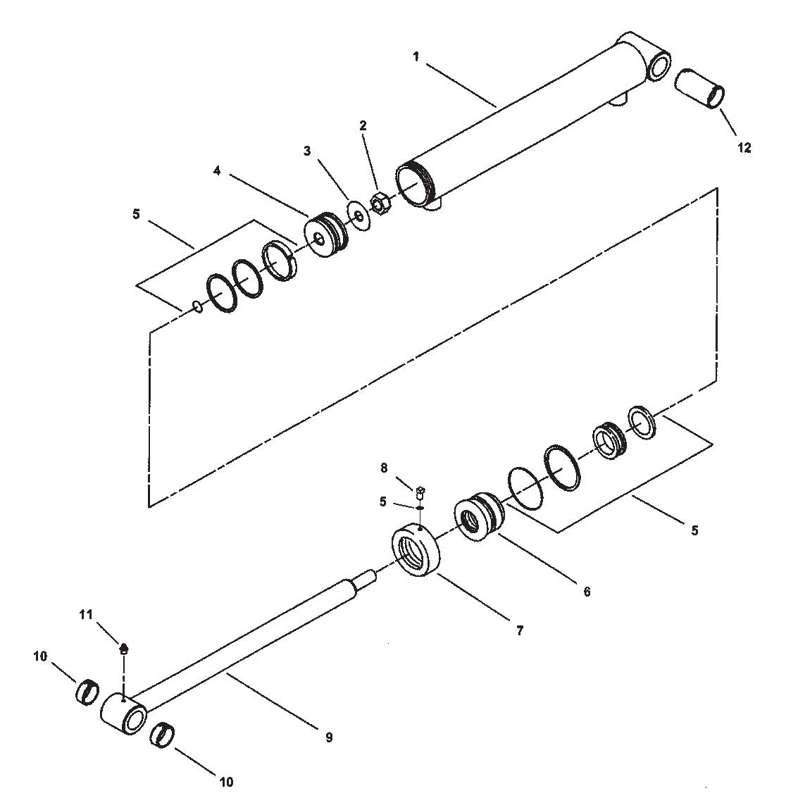

1WELDMENT/BARREL
2NUT/HEX
3WASHER/SPECIAL
4PISTON
5KIT/SEAL
6GLAND
7CAP/HEAD GLAND
8SCREW/SET
9WELDMENT/ROD
10BUSHING/OILITE
11ZERK/GREASE
1WELDMENT/BARREL
2NUT/HEX
3WASHER/SPECIAL
4PISTON
5KIT/SEAL
6GLAND
7CAP/HEAD GLAND
8SCREW/SET
9WELDMENT/ROD
10BUSHING
11ZERK/GREASE
12BUSHING
Lift Cylinder Removal and Installation
Removal Procedure
1.Remove the bucket or attachment.
Warning
BEFORE continuing this service procedure, perform the following SAFETY procedures: plugs/caps in the hoses/tubes to prevent fluid loss and contamination of the hydraulic system.
■ Shut off the engine.
■ Relieve hydraulic system pressure. (For detailed instructions, refer to the Safety chapter in this manual.)
2.Attach a suitable hoist of adequate capacity and a positive locking mechanism able to support the hitch and raise the lift arm to a position where access to the tubes and hoses on the lift cylinder is maximized.
3.Remove the clamp that secures the hydraulic tubes to the lift cylinder.

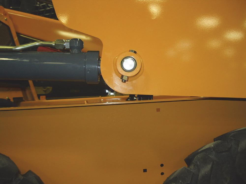
NOTE: To aid in correct reassembly of the hydraulic hoses/tubes, mark the hoses/tubes to be removed BEFORE disassembly in step 3.
4.Disconnect the hydraulic hoses from their hydraulic tubes on the lift cylinder. BE SURE to install

5.Remove the capscrew and locknut securing the front lift cylinder pivot pin. Then drive the pivot pin out to release the rod end of the lift cylinder.
6.Open the engine access cover and lock open the rear grille.
7.While supporting the weight of the lift cylinder, remove the capscrew and locknut securing the rear lift cylinder pivot pin. Drive the pivot pin out the hole on the outside of the chassis. Remove the lift cylinder from the chassis.
8.Remove fittings and any o-rings from the cylinder.
Installation Procedure
1.Attach a suitable hoist of adequate capacity and a positive locking mechanism able to support the hitch and raise the lift arm to a position where access to the tubes and hoses on the lift cylinder is maximized.
2.Install the lift cylinder on the chassis so the rod end is facing forward and the hydraulic tube ports on the cylinder are facing up.
3.Insert the rear and front pivot pins through the lift cylinder pivots and secure them with capscrews and locknuts.
4.Remove the plugs/caps and connect the hydraulic hoses to their hydraulic tubes on the lift cylinder according to the markings made at removal. If no markings were made or new parts were installed, refer to the Hydraulic System chapter exploded views.
5.Secure the lift tubes/hoses to the cylinder with the hose clamp.
NOTE: After removing and/or replacing any component in the hydraulic system, ALWAYS check the level of hydraulic fluid in the reservoir. Add fluid if necessary. Refer to the Lubrication chapter in this manual for the hydraulic fluid requirements and specifications.
Warning
NEVER use your hands to search for hydraulic fluid leaks. Use a piece of cardboard or paper. Escaping fluid under pressure can be invisible and penetrate the skin causing serious injury. If any fluid is injected into your skin, see a doctor at once. Injected fluid MUST be surgically removed by a doctor familiar with this type of injury or gangrene may result.
Warning
ALWAYS wear safety glasses when checking for hydraulic fluid leaks. Escaping fluid under pressure can be invisible and can cause permanent eyesight damage if safety glasses are not worn.
6.ALWAYS check for hydraulic fluid leaks after reassembling components of the hydraulic system.
7.Remove the hoist.
Lift/Tilt Cylinder Disassembly / Assembly
Disassembly Procedure
Remove the cylinder from the skid-steer loader. See “Lift Cylinder Removal” or “Tilt Cylinder Removal” in this chapter.
1.Purge the oil from the cylinder by facing the ports downward and pumping the cylinder rod back and forth several times.
2.Use an Allen wrench to loosen the set screw on the cylinder collar.
3.Clamp a suitable shaft in a vise and slide the cylinder onto the shaft to prevent the cylinder tube from turning.

4.Use a chain clamp or pipe wrench to remove the collar from the cylinder tube.

8.Slide the head and
9.Change the seals as needed.
NOTE: Soaking the seals in warm water prior to installation will make them pliable and easier to install. However, BE SURE to dry them and coat with hydraulic oil for proper installation.
Assembly Procedure
1.Slide the collar onto the cylinder rod (threaded end of the collar should face the threaded end of the cylinder rod).
2.Slide the head gland, larger diameter first, onto the cylinder rod.
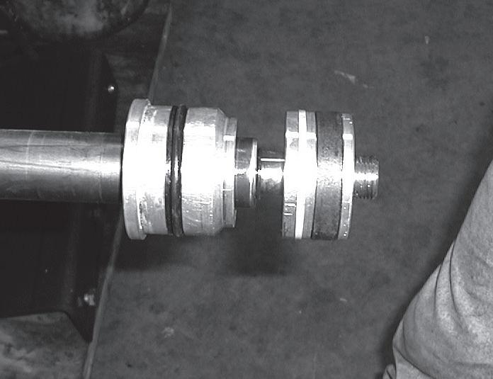
3.Install the piston on the cylinder rod.

4.Secure the head gland and piston on the cylinder rod with a locknut. The locknut should be torqued to 350 ft.-lbs. (474 N•m).
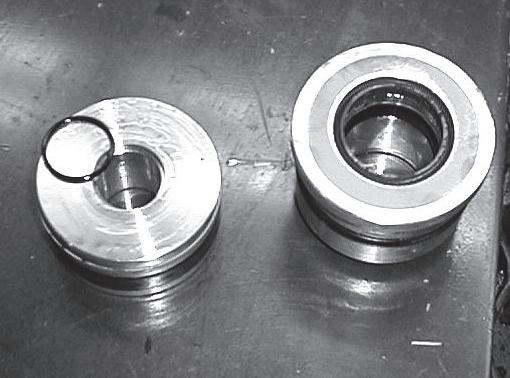
5.Install the cylinder rod into the tube.
6.Slide the collar down to the cylinder tube, thread it onto the tube and tighten with a chain clamp wrench. Tighten the set screw on the collar and torque to 79 ft-lbs. (107 N•m).
7.Install the cylinder on loader. See the “Lift Cylinder Installation” or the “Tilt Cylinder Installation” procedures in this chapter.

Gear Pump Removal and Installation
Removal Procedure
Warning
BEFORE beginning this service procedure, perform the following SAFETY procedures:
■ Remove attachment from lift arm.
■ Raise lift arm; engage lift arm support device.
■ Shut off the engine.
■ Relieve hydraulic system pressure.
■ Tilt back ROPS/FOPS until lock engages. (For detailed instructions, refer to the Safety chapter in this manual.)
1.Drain the oil from the hydraulic reservoir per the procedure in the Lubrication chapter.
2.Loosen the hose clamp on the suction line and pull the hose off the beaded insert. Plug hose and cap the insert.
3.Disconnect two hydraulic pressure hoses at the gear pump.
Note: Mark the hoses, tubes and fittings for reassembly, and cap or plug them after they are disconnected to prevent contaminants from entering the hydraulic system.
4.Position a suitable hoist of adequate capacity and a positive locking mechanism able to support the gear pump. Remove two capscrews securing the gear pump to the hydrostatic pump.
5.Pull the gear pump forward and out of the hydrostatic pump. BE CAREFUL not to lose the o-ring.
Installation Procedure
1.Install the o-ring on the mating surface of the gear pump.
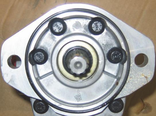
2.Attach the gear pump to the hydrostatic pump (BE SURE the gear pump shaft engages the splined coupler). Install two capscrews with Loctite® 242 applied to secure the gear pump to the hydrostatic pump.
3.Remove the caps/plugs and connect the hydraulic hoses to the gear pump.
4.Install a new hydraulic oil filter.
5.Reinstall the hydraulic reservoir drain plug.
6.Replace the hydraulic oil drained out of the reservoir in step 1.
NOTE: After removing and/or replacing any component in the hydraulic system, ALWAYS check the level of the hydraulic fluid in the reservoir. Add fluid if necessary. Refer to the Lubrication chapter for the hydraulic fluid requirements and specifications.
Warning
NEVER use your hands to search for hydraulic fluid leaks. Use a piece of cardboard or paper. Escaping fluid under pressure can be invisible and penetrate the skin causing serious injury. If any fluid is injected into your skin, see a doctor at once. Injected fluid MUST be surgically removed by a doctor familiar with this type of injury or gangrene may result.
Warning
ALWAYS wear safety glasses when checking for hydraulic fluid leaks. Escaping fluid under pressure can be invisible and can cause permanent eyesight damage if safety glasses are not worn.
7.ALWAYS check for hydraulic fluid leaks after reassembling components of the hydraulic system.
Self-Leveling Valve Removal and Installation

Removal Procedure
Warning
BEFORE beginning this service procedure, perform the following SAFETY procedures:
■ Shut off the engine.
■ Relieve hydraulic system pressure. (For detailed instructions, refer to the Safety chapter in this manual.)
NOTE: Cap or plug the hydraulic hoses and fittings after disconnecting them to prevent fluid loss and contamination of the hydraulic system.
NOTE: In order to remove the hydraulic tubes from their fittings on the self-leveling valve, it may be necessary to loosen the hydraulic tube at the other end to give it some free-play.
1.Open the engine access cover and lock open the rear grille.
2.Disconnect the rear grille electrical harness and move the harness out of the way.
3.Disconnect all the hydraulic tubes from their hydraulic fittings on the self-leveling valve.
7.If replacing, remove the fittings from the valve ports.
NOTE: After removing and/or replacing any component in the hydraulic system, ALWAYS check the level of the hydraulic fluid in the reservoir. Add fluid if necessary. Refer to the Lubrication chapter for the hydraulic fluid requirements and specifications.
Installation Procedure - Follow all warnings first, then reverse the removal steps.
ALWAYS check for hydraulic fluid leaks after reassembling components of the hydraulic system.
Warning
NEVER use your hands to search for hydraulic fluid leaks. Use a piece of cardboard or paper. Escaping fluid under pressure can be invisible and penetrate the skin causing serious injury. If any fluid is injected into your skin, see a doctor at once. Injected fluid MUST be surgically removed by a doctor familiar with this type of injury or gangrene may result.
Warning
ALWAYS wear safety glasses when checking for hydraulic fluid leaks. Escaping fluid under pressure can be invisible and can cause permanent eyesight damage if safety glasses are not worn.
Self-Leveling Valve Adjustment Adjustment Procedure
1.Raise and lower the lift arm several times to ensure there is no air in the hydraulic system.
2.Lower the lift arm completely then fully retract the tilt cylinders (roll back).
3.Raise the lift arm to its maximum height; then lower it to the ground.
4.Measure how far the tilt cylinder rod extends from the tilt cylinder. The distance should be between 81/4 and 8-1/2” (210-216 mm). If measurement is outside this range, the self-leveling valve should be adjusted according to steps 5 - 9 of this procedure.
Warning
BEFORE continuing this service procedure, perform the following SAFETY procedures:
■ Shut off the engine.
■ Surfaces inside the engine compartment may be extremely hot, particularly the engine muffler and exhaust pipes. Serious injury may occur from touching components which have become hot while the engine was running. (For detailed instructions, refer to the Safety chapter in this manual.)
Warning
Surfaces inside the engine compartment may be extremely hot, particularly the engine muffler and exhaust pipes. Serious injury may occur from touching components that have become hot while the engine was running.
5.Open the engine access cover and lock open the rear grille.
6.Loosen the jam nut on the self-leveling valve adjuster screw.


extension. Turn the screw OUT (counterclockwise) to lengthen the cylinder extension.
8.To check for proper operation, lower the ROPS/ FOPS, climb into the operator’s seat, lower the restraint bar and start the engine.
9.Repeat steps 2 through 4 above to check for proper operation of the self-leveling valve. If further adjustment is needed, perform the safety procedures again and repeat steps 7 through 9.
10.After adjustment is complete, tighten the adjuster screw locknut while holding the adjuster screw with the Allen wrench.
Safety Lock Valves - Removal/Installation
Gehl R105 and Mustang 1050R model skid-steer loaders have separate electric solenoid safety interlock valves for the lift, tilt and drive functions of the hydraulic system. The lift safety interlock valve is located behind the ROPS/FOPS on the right side. The tilt safety interlock valve is located on the right side of the chassis, near the self-leveling valve. The brake solenoid valve is located on top the left inside chaincase.
Lift, Tilt and Brake Solenoid Valve Removal Procedure
Warning
BEFORE beginning this service procedure, perform the following SAFETY procedures:
■ Remove attachment from lift arm.
■ Raise lift arm; engage lift arm support device.
■ Shut off the engine.
■ Relieve hydraulic system pressure.
■ Tilt back ROPS/FOPS until lock engages. (For detailed instructions, refer to the Safety chapter in this manual.)
1.Disconnect the electrical connector on the solenoid coil. Disconnect the hydraulic tubes/hoses from their fittings on the solenoid body. Remove all hardware securing the solenoid to the chassis.
2.Remove the solenoid from the skid-steer loader.
NOTE: Cap or plug ALL hydraulic hoses, tubes, fittings, and control valve ports immediately after they are disconnected to prevent fluid loss and contamination of the hydraulic system.

Installation Procedure - Follow all warnings first, then reverse the removal steps.
NOTE: After removing and/or replacing any component in the hydraulic system, ALWAYS check the level of hydraulic fluid in the reservoir. Add fluid if necessary. Refer to the Lubrication chapter for hydraulic fluid requirements and specifications.
Lift, Tilt and Brake Solenoid Valves - Disassembly and Assembly

Lift, tilt and brake solenoid valves can be removed from the loader for parts replacement, but it may not be necessary. If it is necessary, refer to the procedure in this chapter.
Disassembly Procedure
1.Remove the nut that secures the coil to the cartridge.
3.Unscrew cartridge from the valve body.

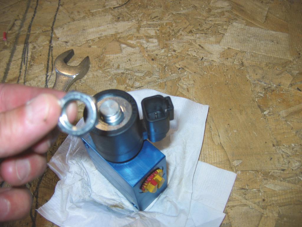
2.Remove the coil from the cartridge.
4.Install seal kit (or other new parts). Assemble solenoid valve in reverse order of disassembly.
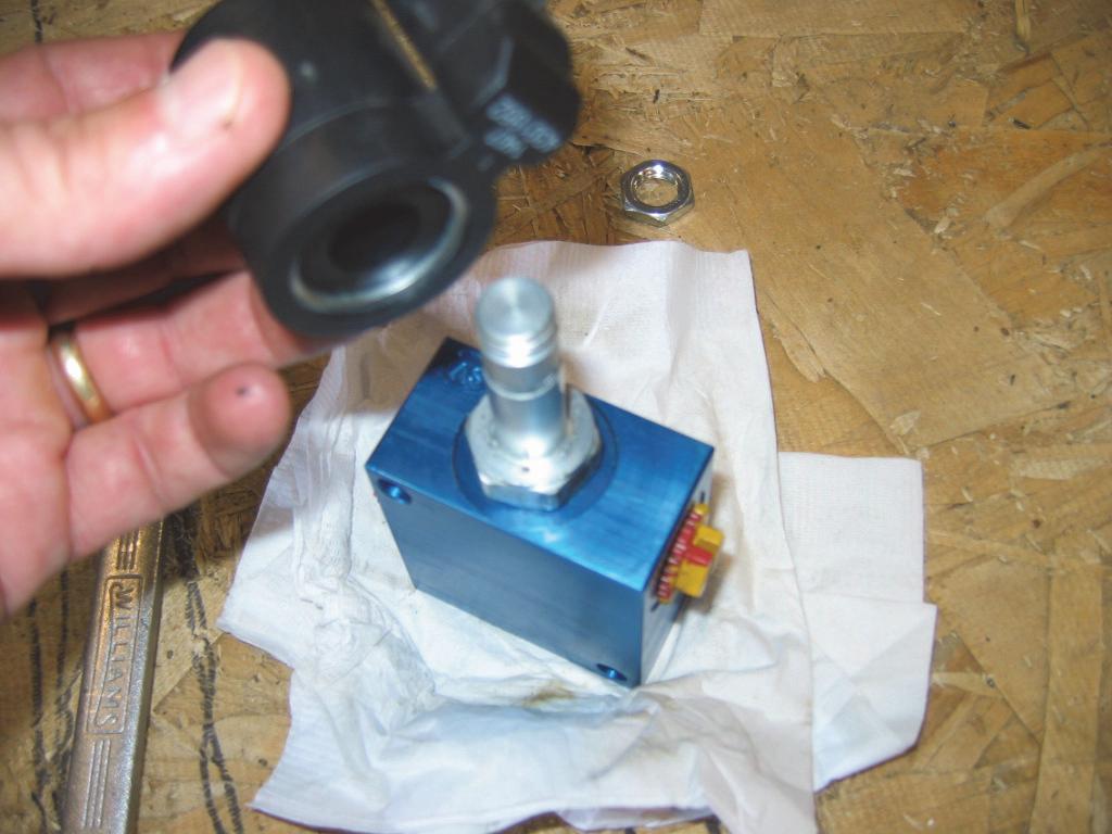
Important
DO NOT torque coil retaining nut more than 45 in.-lbs. (5.1 N•m).
5.If removed from the loader, install the lift, tilt or brake solenoid on the hydraulic system. Refer to the applicable procedure in this chapter.
Main Control Valve Components
NOTES:
1. 192658 IS AN O-RING KIT.
2. 192685 COIL IS AVAILABLE AS SINGLE PART, OR, AS A COMPONENT OF KIT 240285.
Control Valve Removal and Installation
The main hydraulic control valve is located on the right side of the chassis, in front of the engine. This procedure highlights steps for removing the hydraulic hoses/tubes that connect to the control valve in order to remove the control valve. The removal of the lift, tilt and auxiliary connections at the control valve are highlighted in their respective procedures in the Controls chapter of this manual. The control valve ports are numbered for reference.


Removal Procedure
Warning
BEFORE beginning this service procedure, perform the following SAFETY procedures: disconnected to prevent fluid loss and contamination of the hydraulic system.
■ Remove attachment from lift arm.
■ Raise lift arm; engage lift arm support device.
■ Shut off the engine.
■ Relieve hydraulic system pressure.
■ Tilt back ROPS/FOPS until lock engages. (For detailed instructions, refer to the Safety chapter of this manual.)
1.If necessary (see following NOTE), drain oil from hydraulic reservoir. For this procedure refer to “Hydraulic Reservoir” in the Lubrication chapter.
NOTE: If hydraulic hoses and tubes are plugged to prevent oil leakage, it should not be necessary to drain hydraulic reservoir. BE SURE to plug/cap ALL hydraulic hose and tube fittings to prevent contamination of the hydraulic system.
2.Remove control rods and/or cables that control the lift, tilt and auxiliary hydraulics of the skid-steer loader. Refer to their removal procedures in the Controls chapter of this manual.
NOTE: To aid in re-assembly of hydraulic hoses and tubes, mark hoses and tubes to be removed before disassembly.
Installation Procedure
1.Secure the control valve to the chassis with four capscrews and locknuts. If straight or 90° fittings are not in the valve, install them at this time.
2.Port A1: Connect the hydraulic tube to the 90° fitting on the control valve.
3.Port A2: Connect the hydraulic tube to the 90° fitting on the control valve.
4.Port A3: Connect the hydraulic tube to the straight fitting on the control valve.
5.Port B1: Connect the hydraulic tube to the 90° fitting on the control valve.
6.Port B2: Connect the hydraulic tube to the 90° fitting on the control valve.
7.Port B3: Connect the hydraulic tube to the straight fitting on the control valve.
8.Re-connect the auxiliary hydraulics spool lock electrical connector at the front of the control valve.
9.Re-connect the electrical connector at the rear of the control valve.
4.Port B3: Disconnect the hydraulic tube from the straight fitting on the control valve.
5.Port B2: Disconnect the hydraulic tube from the 90° fitting on the control valve.
6.Port B1: Disconnect the hydraulic tube from the 90° fitting on the control valve.
7.Port A3: Disconnect the hydraulic tube from the straight fitting on the control valve.
8.Port A2: Disconnect the hydraulic tube from the 90° fitting on the control valve.
9.Port A1: Disconnect the hydraulic tube from the 90° fitting on the control valve.
10.Remove four screws and locknuts securing the control valve to its mounting bracket.
11.Lift out the control valve. Removal may require loosening the opposite ends of some of the disconnected hydraulic tubes.
NOTE: Cap or plug ALL hydraulic hoses, tubes, fittings and control valve ports immediately after being
10.Connect control rods and/or cables that control the lift, tilt and auxiliary hydraulics of the skid-steer loader. Refer to their installation procedures in the Controls chapter of this service manual.
11.Install hydraulic reservoir drain plug and refill with correct type of hydraulic oil. Refer to the Lubrication chapter for hydraulic oil requirements and specifications.
12.ALWAYS check for hydraulic fluid leaks after reassembling any component of the hydraulic system.
Warning
NEVER use your hands to search for hydraulic fluid leaks. Use a piece of cardboard or paper. Escaping fluid under pressure can be invisible and penetrate the skin causing serious injury. If any fluid is injected into your skin, see a doctor at once. Injected fluid MUST be surgically removed by a doctor familiar with this type of injury or gangrene may result.
Warning
ALWAYS wear safety glasses when checking for hydraulic fluid leaks. Escaping fluid under pressure can be invisible and can cause permanent eyesight damage if safety glasses are not worn.
1.With a wrench, loosen and remove the relief valve from the main control valve.
Main Relief Valve Removal and Installation
A main relief valve is integrated within the control valve. It activates when oil pressure inside the control valve reaches an unacceptable level, to relieve that pressure and prevent damage to valve and the hydraulic system.
Removal Procedure
Warning
BEFORE beginning this service procedure, perform the following SAFETY procedures:
■ Shut off the engine.
■ Relieve hydraulic system pressure.

■ Tilt back ROPS/FOPS until lock engages. (For detailed instructions, refer to the Safety chapter of this manual.)
2.Check condition of o-rings and clean off debris.


