
30 minute read
CHAPTER 12 STORAGE

from Gehl Mixer Feeders 7000 Series MF7210 MF7285 MF7335 MF7435 MF7500 Operators Manual 907060A - PDF

Because a Mixer Feeder is year–round implement, it should be in ready–to–operate condition at all times. Several provisions have been designed into the Mixer Feeder to enable it to be used in cold, moderate and warm outside temperatures. The most important factor for continuous proper operation is lubrication. Routine lubrication should be repeated more frequently in both temperature extremes. If the trailer-type unit is stored outside, BE SURE to remove the Drain Plugs and adjust the Hitchjack to angle the unit to be lower in front, when the unit is NOT being used.
NOTE: When operating the Mixer Feeder in freezing temperatures, the unit should be stored inside, if possible.
Chapter 13 Troubleshooting
NOTE: This Troubleshooting guide presents problems, causes and suggested remedies beyond the extent of loose, worn or missing parts and it was developed with the understanding that the machine is in otherwise good operating condition. Refer to the index at the back of this manual for Chapter and Topic page references. BE SURE to exercise the MANDATORY SAFETY SHUTDOWN PROCEDURE (page 8), BEFORE making any adjustments or repairs.
Miscellaneous Problems
Problem Cause Remedy
Bottom and Top Augers will NOT turn. Obstruction in Augers. Remove obstruction.
Key sheared on Drive Sprocket inside Chain Case. Replace key.
Key on PTO Input Shaft either sheared or missing. Replace key.
Chain has slipped-off Sprocket. Reinstall Chain, being certain that it is tight enough that it does NOT slip off Sprocket; Sprockets MUST be properly aligned.
Shear Bolts are sheared. Replace Shear Bolts.
Star Coupling has come apart. Move Auger towards Chain Case for better engagement. Securely tighten Locking Collars and Set Screws.
Sprockets are coming loose. Set Screws are missing. Replace and/or re-install Cup Point Set Screws.
Set Screws are loose. Re-tighten Set Screws and either place two Screws in the same hole or use Loctite to prevent Screws from vibrating-out.
Chains are hitting each other and/ or other components.
Sprockets are NOT properly aligned. Re-align Sprockets and retighten Sprocket Set Screws.
Chain itself is stretched. Replace Chain.
Locking Collars are missing or loose. Replace and/or re-tighten Locking Collars.
Main Drive Shaft moves. Bearing Collars are missing or loose. Replace and/or re-tighten Locking Collars.
PTO is NOT telescoping properly or damaged.
Lubricate PTO so that is telescopes properly or replace.
MISCELLANEOUS PROBLEMS (Cont.)
Problem Cause Remedy
Two-Piece Discharge Conveyor Cylinder does NOT work.
Hydraulic Hose(s) plugged. Clear obstruction in Hose(s).
Hydraulic Valve is plugged. Clear obstruction in Valve. Leak has developed in Hydraulic system. Carefully locate and repair leak.
Hydraulic system is NOT turned on. Turn on system.
Hydraulic sytem oil level is too low. Refill system to proper oil level in Reservoir.
Feed does NOT come out the Discharge Conveyor. Discharge Conveyor Door is NOT open. Open Door.
Conveyor is NOT operating. Start Discharge Conveyor.
Augers are NOT turning. (See first PROBLEM topic) Conveyor is obstructed. Remove obstruction.
Key on Hydraulic Motor is sheared. Replace Key.
Conveyor Drive Motor is damaged. Repair or replace Motor.
Excessive Chain and/or Sprocket wear. Sprockets are NOT properly aligned. Re-align Sprockets and retighten Sprocket Set Screws.
Chain Case oil bath is empty or too low. Replenish and maintain proper oil level.
Drive Chain(s) will NOT stay properly tensioned.
Tensioner Spring(s) NOT properly adjusted. Readjust Tensioner Spring(s).
Idler Pivot Arm(s) binding. Lubricate until Idler Arm pivots freely.
Tensioner Spring(s) broken. Replace Spring(s).
Scale system is NOT working properly. Trouble with Indicator or Weighbars. Refer to separate Scale manual provided.
CHAPTER 14 SET-UP & ASSEMBLY
General Information
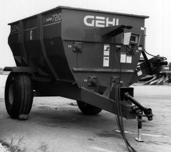
MF7000 Series Trailer-type Mixer Feeders are shipped in varying stages of disassembly, as well as with the optional One-Piece or Two-piece Discharge Conveyor NOT installed. This Set-up & Assembly chapter is divided into two sections; Standard Components and Accessory Components. The following procedures should be performed inside an enclosed workshop which is equipped with the proper tools and an overhead hoist. Although the procedures imply a single set-up person, two people can and will be able to assemble the components to the machine more quickly and easily.
NOTE: The following abbreviations are used herein:
CS-Cap Screw (Hexagon Head)
RHMS-Round Head Machine Screw
SHSS-Socket Head Set Screw
N-Nut (Hexagon)
LN-Lock Nut (Hexagon)
L-Lock (Washer)
P-Plain (Washer)
NPT-National Pipe Thread
Unless otherwise noted, the standard fastening procedure is to secure two parts with a CS, L and N. A part with a mounting slot should be secured with a P against the slotted surfaces. LN’s are sometimes used to prevent two parts from separating but still to allow one part to move or rotate next to the other. Attaching hardware, which will require installation in the path of material flow should always be installed with the head of the screw on the same side of part which will be in contact with the material.
Standard Components
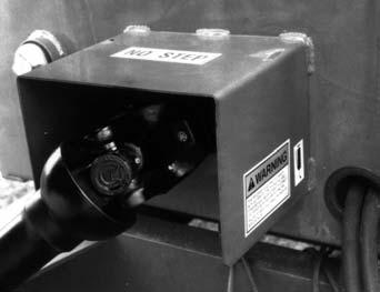
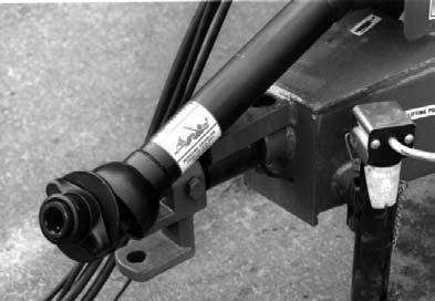
Telescoping PTO Drive
Connect the Telescoping PTO Drive to the Mixer Feeder Drive Shaft making sure that the Shaft is clean and lightly greased before installing the Drive Yoke. Slide the Yoke all the way onto the Shaft and secure it with the Key and Set Screw and the CS and LN.
One-piece Discharge Conveyor (Fig. 28)
NOTE: If Mixer Feeder is going to be set-up with an accessory Single Valve Conversion package, those components should be installed first. The One-piece Discharge Conveyor is shipped in three component subassemblies; the One-piece Conveyor subassembly, the hydraulic Hoses and the completing parts package. Assemble the components of the Onepiece Conveyor to the Mixer Feeder, in the following manner:
1.Using an overhead hoist or other appropriate safe means of raising and supporting the Conveyor assembly, proceed to position and install the Conveyor assembly to the Discharge Door opening. When properly positioned, the top flange of the Conveyor assembly should be below the flange at the bottom of the Discharge Door opening and the Side Panels of the Conveyor should be to the inside of the Mounting Plate on each side of the Discharge Door. Attach the Conveyor Side Panels to the Mounting Plates with (3 each side) 3/8 x 1 CS, N and L. A pair of upper mounting holes are provided in each Mounting Plate to enable attaching the Conveyor assembly in either a 30° or a 40° position. BE SURE that the Conveyor is attached in the same upper mounting hole on both sides. If the 30° position is used, the middle holes will need to be reamed-out to pass a Cap Screw through them. Tightly secure the attaching hardware after all six Cap Screws are installed.
2.Install 90° Elbow Fittings into each of the Motor ports. Install the Check Valve into the Elbow Fitting in the right Motor port (as viewed from the Shaft end). Position both Elbow Fittings so they point away from the shaft of the Motor.
3.Properly position and install the Orbital Motor to the bottom Shaft of the Conveyor with the Shaft Coupler, a 1/4 x 1 Woodruff Key and (2) 5/16 x 5/16 SHSS. When properly positioned, the hydraulic Fittings on the Motor should be next to the Mixer Feeder Frame. Secure the Motor to the Motor Mount Bracket with (4 each) 3/8 x 1 CS & L. Then, tightly secure the (2) SHSS to secure the Motor to the Conveyor Shaft.
4.Route the Hydraulic Hoses as follows: a.For setting-up a unit for a standard hydraulics hookup, pass one end of each of the hydraulic Hoses through the Access Hole in the top of the Front Bearing Stand, over the Drawbar and through Hose Holder at the front lower left corner of Mixer Feeder Tank. b.For setting-up a unit for operation in conjunction with a Single Valve Conversion package, route each of the Hoses coming from the 3-Position Valve with Detent (on left side) over the Drawbar and through the Hose Holder at the front lower left corner of the Mixer Feeder Tank.
5.Connect one Hose to Elbow Fitting on the upper Motor port and connect the other Hose to the Check Valve on the lower Motor port. Install quick-disconnect couplers (purchased locally) to the tractor connection ends of the Hoses. Properly tighten all Hose and Fitting connections before test-running the unit.
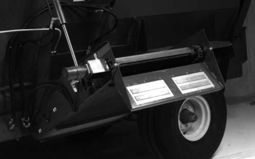
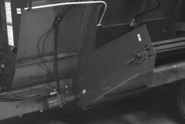
Two-piece Discharge Conveyor (Figs. 29, 30 & 31)
NOTE: If Mixer Feeder is going to be set-up with a Single Valve Conversion package, those components should be installed first.
The Two-piece Discharge Conveyor is shipped in five component subassemblies: the Lower Half Conveyor subassembly, the Upper Half Conveyor subassembly, the Apron Chain, the hydraulic Hoses and the completing parts package. Assemble the components of the Two-piece Conveyor to the Mixer Feeder, in the following manner:
3.Using an overhead hoist or other appropriate safe means of raising and supporting the Conveyor subassembly, proceed to position and install the Lower Half Conveyor subassembly to the Discharge Door opening. When properly positioned, the top flange on the Lower Half Conveyor subassembly should be below the flange at the bottom of the Discharge Door opening. Attach the bottom two holes of the Lower Half Conveyor to the aligning slots in the Conveyor Mount with (2 each side) 3/8 x 1 CS, N, L and a P against all slotted hole surfaces. BE SURE to install the Bolts from the bottom up so that the heads of the Bolts will end up against the bottom. Do NOT tightly secure the attaching hardware at this time.
4.Properly position and loosely attach a Chain Guide on the underside of the Lower Half Conveyor flange at the top two hole positions on each side with (2 each side) 3/8 x 1-1/4 CS, N, L and a P against all slotted hole surfaces. BE SURE to install the Bolts from the bottom up so that the heads of the Bolts will end up against the bottom. Position the lower half approximately in the center of the slots and tightly secure all of the attaching hardware at this time.
5.Properly position and attach the rod end of the Conveyor Lift Cylinder to the Cylinder Lift Bracket with the Cylinder Hinge Pin and (2) 3/16 x 1-3/4 Cotter Pins.
1.From inside the Mixer Feeder, install the Conveyor Cylinder Backing Plate with (4) 3/8 x 1-1/4 CS through the holes provided. Then, properly position and install the Cylinder Lift Bracket over the (4) CS and attach the Bracket with (4 each) 3/8 P, L and N. Tightly secure the attaching hardware.
2.On the insides of the right and left Conveyor Mounts on each side of the Discharge Door opening, properly position and attach the respective Right and Left Mounting Plates with (2 each) 3/8 x 1 CS, L and N. Tightly secure attaching hardware.
6.Using an overhead hoist or other appropriate safe means of raising and supporting the Upper Half Conveyor subassembly, proceed to position and install the Upper Half Conveyor subassembly onto the Pivot Tube of the Lower Half Conveyor subassembly. Secure the two subassemblies together with a 1/2 x 3-1/4 CS and LN and Spacer on each side. Tighten the LN enough to prevent the CS from falling-out but to allow the Upper Half to pivot freely.
7.Raise the top end of the Upper Half Conveyor to align the end of the Anchor Stud with Clevis on the end of the Cylinder. Place one end of the Clevis onto the Stud, install the Bushing and slide the Clevis all the way onto the Stud. Install a 5/16 x 1 CS, L and N through the Bushing and Stud to secure the assembly. As long as there are NO Hose connections to the Cylinder ports and the shipping plugs have been removed, the Conveyor can be pulled-down.
8.Connect the Shaft Coupler to the Orbital Motor Shaft with the 1/4 x 1 Woodruff Key and tighten the 5/16 x 5/16 SHSS. Properly position (with port facing “up”) and install the Orbital Motor and Shaft Coupler to the Upper Half Conveyor Shaft and secure the Motor to the Motor Mount Bracket with (4 each) 3/8 x 1 CS and L. Then, secure the Shaft Coupler to the Conveyor Shaft with the other 5/16 x 5/16 SHSS.
9.Looking opposite the Shaft end of the Orbital Motor, install a Tee Fitting into the right Motor port, the Check Valve into the left Motor port and the other Tee Fitting into the Check Valve. osition the Fittings so that the Tee connections are parallel to the Motor Shaft.
10.With the Conveyor in the completely lowered position, properly position and place the Conveyor Apron onto the Conveyor. Slide the Apron down the Conveyor and route it around the Sprocket on the Lower Half Conveyor Shaft. Then, pass two pieces of wire between the Conveyor Slide and the bottom of the Conveyor and, working through the Cleanout Door opening, attach a wire to each Conveyor Chain. With equal pressure, draw both ends of the Apron Chain to the top end of the Upper Half Conveyor so that the two ends of each Apron Chain can be coupled together. After the ends of the Apron have been properly coupled together, refer to the Adjustments chapter for Apron Chain tension adjustment details. As necessary, remove the appropriate number of Links from each side of the Chain to facilitate adjustment.
11.Install a 90° Elbow Fitting into each Cylinder port and position the Fittings so that the Elbows face each other. Then, attach one short Hose between the rod end Elbow on the Cylinder and leg of the Tee into the Check Valve which is facing away from the Conveyor. Similarly, attach the other short Hose between the anchor end Elbow on the Cylinder and the leg of the other Tee in the Orbital Motor which is facing away from the Conveyor.
12.Route the Hydraulic Hoses as follows: a.For setting-up a unit for a standard hydraulics hookup, pass one end of each of the hydraulic Hoses through the Access Hole in the top of the Front Bearing Stand and route the ends of the Hoses along the same path as the Door Cylinder Hoses. b.For setting-up a unit for operation in conjunction with a Single Valve Conversion package, route each of the Hoses coming from the 3-Position Valve with Detent (on left side), through the Access Hole in the front base of the Mixer Feeder Tank and along the same path as the Door Cylinder Hoses.
13.Once through the Access Hole in the left Frame member, route the Hoses along the side of the Discharge Conveyor and connect one Hose to the open leg of each Tee Fitting on the Orbital Motor. For a standard hydraulics hookup, install quickdisconnect couplers (purchased locally) to the tractor connection ends of the Hoses. After the connections have been made to the Tee Fittings, anchor both Hoses to the side of the Upper Half Conveyor with the two Tube Clips and attach both Clips with a 1/4 x 1-1/4 CS, (2) P, L and N. Make sure all hardware and Fitting connections are tight before test-running the unit.
14.Raise the Conveyor all the way up and install the Cleanout Door in the direction shown in Fig. 31.

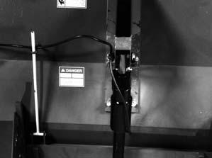
WEIGH SCALE INDICATOR (Figs. 32, 33, 34, 35 & 36)
Mount and secure the Indicator to the Indicator Mounting Bracket with the two fasteneres provided with the Indicator.
After the Indicator and Extended-view Indicator
Mounting parts are installed, use the Cable Clips (provided) to anchor the Power and Junction Box Cords to the bottom side edge of the Indicator Support as shown in Fig. 32.
Refer to the Power Connection drawings provided for additional information on the Trailer Connection mounting and battery power supply connections to the tractor.
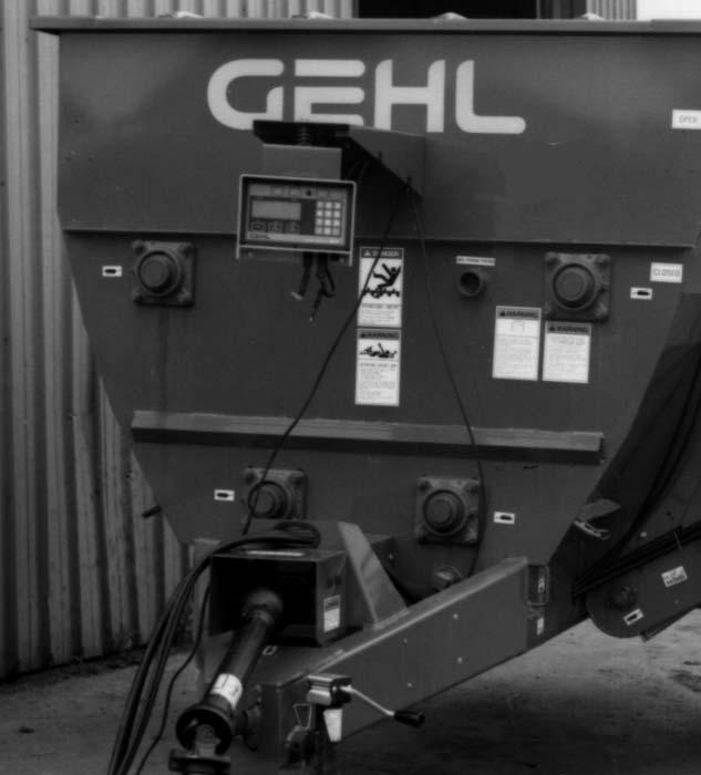
The Weigh Scale Indicator is shipped separate of the Mixer Feeder and MUST be installed in a convenient location on the unit. Typically, the Indicator is installed using an Extended-view Indicator Mounting package. This package enables mounting the Indicator out from the front of the Mixer Feeder so that it can be conveniently pivoted for viewing from the front or side of the Mixer Feeder. BE SURE to select the appropriate position for attaching the Indicator Support to avoid covering up the Danger Decal, 091442. Locate the Support in the middle of the Tank (or slightly to the left of center) and just above the ledge, as shown. Refer to the exploded-view drawing and associated parts list and assemble the components as shown. Use the Indicator Support as a template for marking and drilling the four (4) 13/32″ diameter mounting holes in the front of the Tank. Mount the Indicator Support to the Tank with (4 each) 3/8 x 3/4 CS, L and N. Attach the Indicator Bracket to the Indicator Support with the 1/2 x 3 CS, 3 P, Compression Spring and NILN, as shown in Fig. 33. Then, attach the Indicator Mounting Bracket to the Indicator Bracket with (4 each) 1/4 x 1/2 CS, N and L.
Power Connections
NOTE: When required and if NOT already done, make sure that the Weigh Bar is installed with the identifying arrow facing “up”. Weighbar Spindles should be installed with “TOP” facing up. Refer to the Indicator manual, provided, for additional set-up and assembly, calibration and operation information.
Fig.
Accessory Components
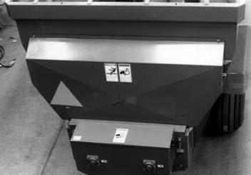
Battery Mount Package (Fig. 37)
The Accessory Battery Mount is designed to enable operating the Trailer-type or Truck-mounted Mixer Feeder Weigh Scale system with a 12 volt D.C. wet cell battery independently of the tractor or truck electrical system. The Battery Mount consists of the Mount Case, a Case Cover and attaching hardware. A photograph of a typical installation is provided. The four 13/32″ diameter holes, for attaching the Mount Case, will have to be drilled through the front of the Mixer Feeder, using the Case as a template. The 12 volt battery is to be purchased locally.
Route the Power Cord through the side of the Battery Case and attach the black and white Power Leads of the Tractor Plug (shown in Figs. 34, 35 & 36) to the Battery, using the appropriate Terminal connectors.
Handling Battery Safely WARNING
Explosive gas is produced while a Battery is in use or being charged. Keep flames or sparks away from the Battery area. Make sure Battery is charged in a well-ventilated area.
NEVER lay a metal object on top of a Battery as a short circuit can result.
Battery acid is harmful on contact with skin or fabrics. If acid spills, follow these first aid tips:
1.Immediately remove any clothing on which acid spills.
2.If acid contacts the skin, rinse the affected area with running water for 10 to 15 minutes.
3.If acid comes in contact with the eyes, flood the eyes with running water for 10 to 15 minutes. See a doctor at once. NEVER use any medication or eye drops unless prescribed by the doctor.
4.To neutralize acid spilled on the floor, use one of the following mixtures: a.1 pound (0.5 kg) of baking soda in 1 U.S. Gallon (4 liters) of water b.1 Pint (0.4 liters) of household ammonia in 1 U.S. Gallon (4 liters) of water
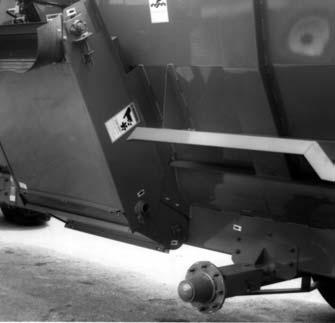
Discharge Conveyor Magnet (Fig. 38)
The Accessory Discharge Conveyor Magnet assembly can be installed on the end of either the One-piece or the Two-piece Discharge Conveyor. To install the Magnet assembly on either Conveyor, first remove the Belt Deflector, Deflector Strap and the attaching hardware. Then, properly position and install the Magnet assembly with (4 each of the original) 1/4 x 3/4 CS, L and N, on the bottom flange.Then, using the Magnet as a template, locate and drill two (2) 13/32″ diameter holes for the top corners. Then secure the Magnet with a 3/8 x 1 CS, (2) P and LN, in each top corner.
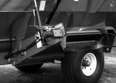
Single Valve Conversion Package (Figs. 13-12 & 13-13)
The Single Valve Conversion package is designed to be installed on a Trailer-type Mixer Feeder that will be operated by a tractor with only one remote hydraulics circuit. Proceed as follows:
NOTE: These instructions are developed in consideration of the Mixer Feeder being adapted with the Single Valve Conversion package before the One-piece or Two-piece Conveyor is installed. Hose connections between the Door Cylinder and the Conveyor Lift Cylinder and/or Orbital Motor MUST be made to the Single Valve Conversion Valves before they are attached to their respective Cylinder(s) and Motor Fittings.
1.Begin by selecting the desired mounting position in the middle of the flange on the front of the Mixer Feeder. Using the Valve Mount as a template, locate and drill (2) 13/32″ diameter mounting holes in the flange.
2.Properly position and attach the Valve Mount to the flange with (2 each) 3/8 x 1 CS, L and N.
3.Couple the output port of the Valve with 3-Position Detent to the input port of the Valve (without Detent) with the 1/2″ Close Nipple. Screw the Valves together onto the Close Nipple until both Valves are facing the same direction.
4.Using (3 each) 3/8 x 1-3/4 CS, P, L and N, secure both Valves to the Valve Mount in the position and direction shown.
5.Install a 90° Elbow Fitting into the input port of the Valve with 3-Position Detent and into the output port of the Valve (without Detent). position the Fittings so that the Elbows face away from the Valve Mount.
6.Properly position and loosely attach the Brace to the hole in the Valve Mount Pipe with a 3/8 x 2 CS, L and N. Then, level the Valve Mount and align the other end of the Brace to mark the hole location in the front of the Mixer Feeder for securing the Brace. With the hole marked, drill a 13/32″ diameter hole through the front of the Mixer Feeder and secure the Brace with a 3/8 x 1 CS, L and N.
7.Properly position and install the Hanger over the end of the Valve Mount Pipe and temporarily secure it with the CS. Pass a Console Handle through each hole in the Hanger and slide a Valve Handle into each Console Handle. Link a Valve Handle to each Valve Lever Knob by installing a 1/8 x 1 Cotter Pin through the hole in each Valve Handle. With both Valves in their “neutral” positions, tighten the Lock Screws on each Console Handle.
8.Install the long Hose onto each Elbow Fitting. Pass the Hoses through the Access Hole in the top of the Front Bearing Stand. Install quick-disconnect couplers (purchased locally) to the tractor connection ends of the long Hoses.
9.Temporarily detach the Hose Clips that anchor the existing Hoses routed to the Relief Valve on the Door Cylinder and disconnect these Hoses from the Relief Valve so that the ends of the Hoses will pivot freely. Take the Hoses for the Door Cylinder out of the Access Hole in the Front Bearing Stand and connect the ends of the Hoses to the two ports of the Valve (without Detent) on the right side. After the connections are made to the Valve, the Relief Valve connections can be restored and the Hose Clips can be re-anchored.
10.In a similar manner, make the Hose connections to the 3-Position Valve with Detent, on the left side, and route these Hoses per details given under the One-piece or Two-piece Discharge Conveyor topics.
11.Because the Single Valve Conversion assembly and interconnection Hoses cover-up the factory installed DANGER Decal 091442 and WARNING Decal 093653, each Decal is provided in the Kit of parts and should be attached to the front of the Mixer Feeder in the position indicated. Refer to Chapter 16, Decal Locations, for new Decal application information.
Self-contained Hydraulics
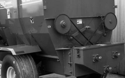
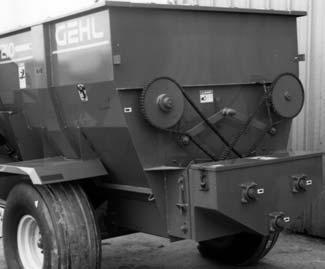
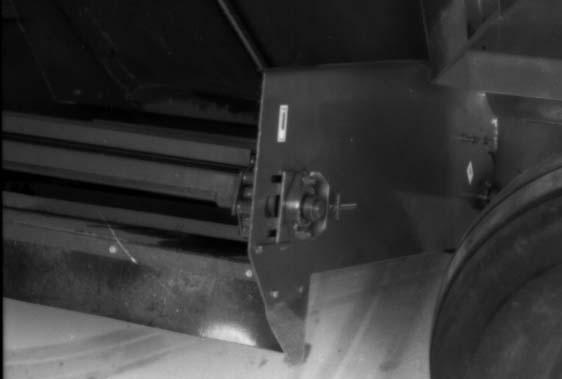
Pump & Drive Chain (Fig. 43)
3.Loosen the two Lock Collars on the lower Input Shaft of the Chaincase.
4.Slide the lower Input Shaft backwards until it is approximately half way out of the Chaincase. BE CAREFUL so as NOT to damage the Oil Seals .
5.Place Sprocket and Key onto lower Input Shaft.
6.Carefully slide the lower Input Shaft back into its original position.
7.Tighten the two Lock Collars on the lower Input Shaft.
To install the Accessory Self-contained Hydraulics package on any Trailer-type Mixer Feeder (except the MF7210), proceed as follows:
1.Refer to Fig. 40 and remove the large Rear Shield and the two Roller Chains that drive the upper Augers.
2.Refer to Fig. 41 and remove and discard the Gear Pump Cover Plate from inside the Chaincase.
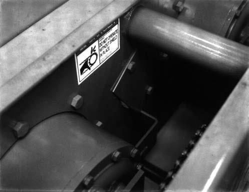
8.Install the Fittings into Hydraulic Pump. The 1-5/16 to 3/4 Fitting goes into the Inlet Port of the Pump, while the 1-5/16 to 1/2 Fitting goes into the Outlet Port. The 3/4 Elbow then goes into the 3/4 Fitting. When installed, the Elbow should face away from the Shaft of the Pump and will be turned to its final position later.
9.Apply silicon (or other sealing compound) on the face of the Pump and install it from the front side of the Chaincase into the hole, where the Gear Pump Cover Plate was installed, so that Pump Shaft extends into Chaincase. The Elbow Fitting should be facing up. Use the 1/2 x 1-3/4 CS, L and N, to attach the Pump.
10.Install the Sprocket and Key onto the Shaft of the Pump.
11.Put the Chain over the Sprocket on the Input Shaft and the Sprocket on the Pump.
12.Install the Idler Sprocket onto the Idler Guide using the 5/8 x 2-1/4 Cap Screw, Nut and Shim Washers, as required.
13.Align the Sprocket on the Pump with the Sprocket on the Input Shaft and tighten the Set Screws in the Sprockets.
14.Tighten the Roller Chain.
Reservoir & Filter (Fig. 44)
15.Install the Oil Filter Head assembly onto the side of the Oil Reservoir. Install the Elbow into the other side of the Filter Head assembly.
16.Mount the Oil Reservoir onto the left rear side of the box by drilling 3/8 holes in the box. The top of the Oil Reservoir should be even with the bend line in the Side Sheet. Use 3/8 x 1 Cap Screws, L & N to attach the Reservoir.
17.Attach the 3/4 x 60” Hydraulic Hose to the bottom of the Oil Reservoir. Attach the other end of this Hose to the Elbow on top of the Hydraulic Pump on the Chaincase. Route the Hose through the hole in the End Panel.
18.Attach the 1/2 x 276” Hydraulic Hose to the bottom port on the Hydraulic Pump. Route the other end of this Hose along the frame rail of the Mixer Feeder up to the area where the control components will be installed per the following information.
19.Attach the 1/2 x 300” Hydraulic Hose to the Elbow on the Filter of the Reservoir Pump. Run this Hose through the hole in the End Panel and then along the Frame Rail of the Mixer Feeder up to the control components.
Control Components (Fig. 44)
20.Begin by selecting the desired mounting position in the middle of the flange on the front of the Mixer Feeder. Using the Valve Mount as a template, locate and drill (2) 13/32″ diameter mounting hole in the flange.
21.Properly position and attach the Valve Mount to the flange with (2 each) 3/8 x 1 CS, L and N.
22.Couple the output port of the Valve with 3-Position Detent to the input port of the Valve (without Detent) with the 1/2″ Close Nipple. Screw the Valves together onto the Close Nipple until both Valves are facing the same direction.
23.Using (3 each) 3/8 x 1-3/4 CS, P, L and N, secure both Valves to the Valve Mount in the position and direction shown.
24.Install a 90° Elbow Fitting into the input port of the Valve with 3-Position Detent and into the output port of the Valve (without Detent). position the Fittings so that the Elbows face away from the Valve Mount.
25.Properly position and loosely attach the Brace to the hole in the Valve Mount Pipe with a 3/8 x 2 CS, L and N. Then, level the Valve Mount and align the other end of the Brace to mark the hole location in the front of the Mixer Feeder for securing the Brace. With the hole marked, drill a 13/32″ diameter hole through the front of the Mixer Feeder and secure the Brace with a 3/8 x 1 CS, L and N.
26.Properly position and install the Hanger over the end of the Valve Mount Pipe and temporarily secure it with the CS. Pass a Console Handle through each hole in the Hanger and slide a Valve Handle into each Console Handle. Link a Valve Handle to each Valve Lever Knob by installing a 1/8 x 1 Cotter Pin through the hole in each Valve Handle. With both Valves in their “neutral” positions, tighten the Lock Screws on each Console Handle.
27.Temporarily detach the Hose Clips that anchor the existing Hoses routed to the Relief Valve on the Door Cylinder and disconnect these Hoses from the Relief Valve so that the ends of the Hoses will pivot freely. Take the Hoses for the Door Cylinder out of the Access Hole in the Front Bearing Stand and connect the ends of the Hoses to the two ports of the Valve (without Detent) on the right side. After the connections are made to the Valve, the Relief Valve connections can be restored and the Hose Clips can be re-anchored.
28.In a similar manner, make the Hose connections to the 3-Position Valve with Detent, on the left side, and route these Hoses per details given under the One-piece or Two-piece Discharge Conveyor topics.
29.The Hydraulic Hose which comes from the Hydraulic Pump in the Chaincase is connected to the Input Port of the Valve with 3-Position Detent.
30.The Hydraulic Hose which comes from the Oil Filter on the Oil Reservoir is connected to the Output Port of the Valve without 3-Position Detent.
31.Replace and retention the Upper Auger Drive Chains and replace and resecure the large Rear Shield.
32.Because some of the control components coverup the original factory installed DANGER Decal and WARNING Decal, both Decals are provided with the Kit of parts and should be attached to the front of the Mixer Feeder in the position indicated. Refer to Chapter 16, Decal Locations, for new Decal application information.
1000 RPM Conversion Kits (Fig. 45)
This Instruction provides illustrated details for installation of the 1000 RPM PTO Conversion Kits 092694 and 092780 onto any MF7000 Series trailer-type Mixer Feeder (except the MF7210 model). Installation involves replacement of the (2 each) original 21T and 27T Sprockets with respective 30T and 21T Sprockets, adding Offset Links to both Drive Chains, replacing the original Chaincase Input Drive Shear Bolt, and, replacing the Telescoping PTO Drive assembly.
Warning
BEFORE proceeding, exercise the following MANDATORY SAFETY SHUTDOWN PROCEDURE:
1. Disengage the tractor PTO.
2. Shut off the tractor engine, remove the starter key and take it with you.
3. Wait for all movement to stop.
4. Remove the Telescoping PTO Drive and ALL power connections from the tractor.
Proceed as follows: a.For 7285 or 7335 units with Slide Lock Coupler, replace Grade 8 Shearbolt with the Grade 5 Shear Bolt furnished in the Kit. b.For 7435 or 7500 units, secure the Star Coupler to the Input Shaft with the original Bolt.
1.Place an oil catch pan under the Chaincase, remove the Drain Plug and drain the oil out of the Chaincase.
2.Loosen (but do NOT remove) the (4 each) Cap Screws that secure the four Bearing Housings. Loosen and remove all Bearing Lock Collars.
3.Loosen (but do NOT remove) the Cap Screw that secures each Chain Idler and move each Idler to loosen Chain tension. Locate and detach the Chain Couplers, split both Chains and remove them.
NOTE: Observe the Chain routing around the various Sprockets so that the original routing can be restored after the appropriate Sprockets are changed.
4.Move each of the Planetary Gearbox Drive Shafts rearward so that the original 21T Sprocket can be slid off the Shaft and replaced with a 30T Sprocket. Then, reposition each Shaft so that it properly engages its Planetary Gearbox.
5.Move the Input Shaft rearward so that the two original 27T Sprockets can be slid off the Shaft and replaced with the two 21T Sprockets. Then, reposition the Input Shaft so that it properly engages the Coupler.
6.After all of the new Sprockets have been installed, retighten the attaching hardware on all four Bearing Housings. Then, replace and retighten the Lock Collars.
7.Reinstall and re-couple the two Drive Chains by adding the Offset Links to obtain the necessary additional lengths required. Then, restore proper Drive Chain tension by adjusting the Idler positions and tightly secure the Idler attaching hardware.
8.Loosen the Set Screw and remove the Cap Screw to detach the 540 RPM Telescoping PTO Drive Shaft from the Line Shaft. Properly orient and install the 1000 RPM Telescoping PTO Drive Shaft furnished with the Kit.
04092697a MF7285/7335 PTO SHAFT ASS’Y1 04092781a MF7435/7500 PTO SHAFT ASS’Y1 b CS 1/4X2 GR 5 (LATER STYLE) 1 a) Not available for repair as a complete assembly;see pages titled UNIVERSAL DRIVES, in appropriate Service Parts Manual. b) For replacement,order Shear Bolt Kit 080453 containing 8 Bolts & LN.
Chapter 15
OPTIONAL FEATURES & ACCESSORIESS
Most of the optional features & accessories, listed in this chapter, are covered by information listed in the Set-up & Assembly chapter. Some accessories are shipped with separate instructions to install. Refer to your Gehl “Farm Equipment Suggested List Prices” for stock numbers and ordering information.
Scale Power Battery Box Accessory
An accessory Battery Box is available. Installation details are provided in the Set–up & Assembly chapter.
Discharge Conveyor Options
The Trailer-type or Truck-mounted Mixer Feeder Discharge Conveyor MUST be ordered separately and dealer installed.
One–Piece Conveyor
Trailer-type and Truck-mounted Mixer Feeders can be equipped with a One–Piece, Two–Position (fixed 30° or 40°) Discharge Conveyor. Installation instructions are provided in the Set–up & Assembly chapter.
Two–Piece Conveyor
Trailer-type and Truck-mounted Mixer Feeders can be equipped with a two–Piece, hydraulic raise–lower–type Discharge Conveyor. Installation instructions are provided in the Set–up & Assembly chapter.
Discharge Conveyor Magnet Accessory
An accessory Magnet Assembly can be obtained for field installation onto the end of either the One–Piece or the Two–Piece Discharge Conveyor assembly. Installation details are provided in the Set–up & Assembly chapter.
Safety Chain Accessories
If the Mixer Feeder is going to be transported on a public highway, a Safety Chain package should be obtained and installed per details in the Transporting chapter. Depending on the size Mixer Feeder, two different Safety Chain packages are available.
SCALES & ACCESSORIES
All Mixer Feeders are provided with Weigh Scale Systems. Weighbars are factory installed and the customer can order any one of the three model Scale Indicators for field mounting per details in the Set-up & Assembly chapter information. Accessory Audible and Visual Alarms are also available.
Shear Bolt Service Accessories
Shear Bolts are used on specific parts of the various model Mixer Feeders. Replacement Shear Bolts and Locknuts are available in packaged quantities of (8) Bolts and Locknuts per package. Part numbers for the various Shear Bolt packages are provided in the Operation chapter.
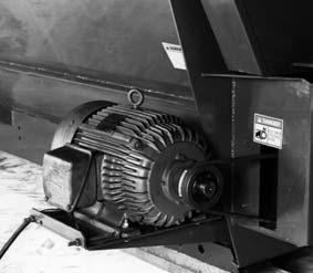
SELF-CONTAINED HYDRAULICS ACCESSORY
An accessory Self-contained Hydraulics package is available for installation onto a Trailer-type Mixer Feeder (except MF7210) which is going to be operated by a tractor with NO (or otherwise an inadequate) remote hydraulic output. Installation details are provided in the Set–up & Assembly chapter.
Single Valve Conversion Accessory
An accessory Single Valve Conversion package is available for installation onto a Trailer-type Mixer Feeder which is going to be operated by a tractor with only one remote hydraulics output. Installation details are provided in the Set–up & Assembly chapter.
1000 Rpm Conversion Accessory
An accessory 1000 RPM Conversion Kit is available for installation onto a Trailer-type Mixer Feeder (except MF7210) which is going to be operated by a tractor with a 1000 RPM PTO. Installation details are provided in the Set–up & Assembly chapter.
WHEEL & TIRE OPTIONS
As desired or required, some model Mixer Feeders are available with different selectable Wheel and Tire options.
Chapter 16 Decal Locations
General Information
Decal Location information is provided to assist in the proper selection and application of new decals, in the event the original decal(s) become(s) damaged or the machine is repainted. Refer to the listing for the illustration reference number, part number, description and quantity of each decal provided in the Kit. Refer to the appropriate illustration(s) for replacement location(s).
NOTE: Refer to the SAFETY Chapter of the Operator’s Manual for the specific information provided on all of the various Safety Decals furnished in the Decal Kit(s).
To ensure proper selection for correct replacement decal(s), compare all of the various close-up location photographs to your machine BEFORE starting to refinish the unit. Then, circle each pictured decal (applicable to your machine) while checking-off its part number in the listing. After you have verified all the decals needed for replacement, set aside unneeded decals for disposal.
New Decal Application
Surfaces MUST be free from dirt, dust, grease and other foreign material before applying the new decal. To apply a solid-formed decal, remove the smaller portion of the decal backing paper and apply this part of the exposed adhesive backing to the clean surface while maintaining proper position and alignment. Slowly peel off the other portion of the backing paper while applying hand pressure to smooth-out the decal surface.
Caution
ALWAYS observe Safety Rules shown on Decals. If Decals become damaged, or if the unit is repainted, replace the Decals. If repainting, BE SURE that ALL Decals from the Kit(s) which apply to your machine, are affixed to your unit.
The Decal Set Number for the MF7210 is 113349, for the MF7285 is 113350, for the MF7335 is 113351, for the MF7435 is 113352 and. for the MF7500 is 113353. The Sets include the following:
PAINT NOTICE
Use this list to order paint for refinishing:
906315One Gal. AG Red
906324One Qt. Light Grey
9063166 (12 oz. Spray Cans) AG Red
9063256 (12 oz. Spray Cans) Light Grey
NOTE: Order adequate numbers of Part Number 126757 for 10 ft rolls of replacement Striping.
Ref.Part No.No.Description & Quantity
1047272SMV (Slow Moving Vehicle)
2067493Red Reflector (3 Places)
3067926Amber Reflector
4060510Jack Storage Position
5060511Jack Lifting Position
6080247NO Step
7091438WARNING - Chain Drive (2 Places)
8091440DANGER - Do NOT Operate With Shield Missing (2 or 3 Places)
9091442DANGER - Rotating Auger (4 Places)
10091444DANGER - Rotating Component
11091446ATTENTION - Add Lubrication (1 or 2 Places)
12091447Open
13091448Closed
14091727WARNING – Automatic Conveyor (2 Places)(Two–Piece Conveyor Only)
15092282WARNING – Electrical Component Compliance (Stationary-mounted ONLY)
16093020Lubrication Symbol (19* Places) (18* Places 7210 ONLY)
17093367WARNING - Owner’s Responsibility & Read Manual
18093369WARNING - Hydraulic Oil & Unplugging
19093373WARNING - General Safety
20093466WARNING - 540 RPM Operation ONLY
093465WARNING - 1000 RPM Operation ONLY (1000 RPM Converted Units ONLY)
21093489WARNING - Pinch Point
22093653WARNING - Rotating Drive Line
23093967DANGER - Rotating Component (Stationary-mounted ONLY)
24094951Made in USA
25094963Colorbar (2 Places)
260950407210 (2 Places, see NOTE below)
0950417285 (2 Places, see NOTE below)
0950427335 (2 Places, see NOTE below)
0950387435 (2 Places, see NOTE below)
0950437500 (2 Places, see NOTE below)
27112710TMR COW (2 Places)
28122617GEHL
29122736GEHL (2 Places)
NOTE: Decal sets vary only by the model number Decals (item 26). * Quantities based on 2-piece Conveyor requirements.

NOTE: This list is a repeat of the Decal List on a previous page and is provided for your convenience when selecting Decals from the second page of photographs.
Ref.Part
No.No.Description & Quantity
1047272SMV (Slow Moving Vehicle)
2067493Red Reflector (3 Places)
3067926Amber Reflector
4060510Jack Storage Position
5060511Jack Lifting Position
6080247NO Step
7091438WARNING - Chain Drive (2 Places)
8091440DANGER - Do NOT Operate With Shield Missing (2 or 3 Places)
9091442DANGER - Rotating Auger (4 Places)
10091444DANGER - Rotating Component
11091446ATTENTION - Add Lubrication (1 or 2 Places)
12091447Open
13091448Closed
14091727WARNING – Automatic Conveyor (2 Places)(Two–Piece Conveyor Only)
15092282WARNING – Electrical Component Compliance (Stationary-mounted ONLY)
16093020Lubrication Symbol (19* Places) (18* Places 7210 ONLY)
17093367WARNING - Owner’s Responsibility & Read Manual
18093369WARNING - Hydraulic Oil & Unplugging
19093373WARNING - General Safety
20093466WARNING - 540 RPM Operation ONLY
093465WARNING - 1000 RPM Operation ONLY (1000 RPM Converted Units ONLY)
21093489WARNING - Pinch Point
22093653WARNING - Rotating Drive Line
23093967DANGER - Rotating Component (Stationary-mounted ONLY)
24094951Made in USA
25094963Colorbar (2 Places)
260950407210 (2 Places, see NOTE below)
0950417285 (2 Places, see NOTE below)
0950427335 (2 Places, see NOTE below)
0950387435 (2 Places, see NOTE below)
0950437500 (2 Places, see NOTE below)
27112710TMR COW (2 Places)
28122617GEHL
29122736GEHL (2 Places)
NOTE: Decal sets vary only by the model number Decals (item 26). * Quantities based on 2-piece Conveyor requirements.

Chapter 17 Maintenance Log
SERVICE EVERY 10 HOURS (or daily)
COMPONENT and SERVICE REQUIRED
PROCEDURE and/or CHAPTER TOPIC REFERENCE (Check Page No. in Index)
Lubricate Telescoping PTO Drive Grease Fittings. Refer to Lubrication chapter for Grease Fitting locations.
Date After Service is Completed
SERVICE EVERY 50 HOURS (or monthly)
Check Tire pressures and retorque Wheel Lugs. Refer to Service chapter.
Check Drive Chain and Conveyor Apron tensions. Refer to Adjustments chapter.
Lubricate appropriate grease fittings. Refer to Lubrication chapter.
On Two–Pieces Discharge Conveyor Models, clean–out debris through Cleanout Door.
Refer to Service chapter.
Check Chaincase Oil Level. Refer to Lubrication chapter.
Check Planetary Gearbox Oil Levels. Refer to Lubrication chapter.
Date After Service is Completed
SERVICE EVERY 500 HOURS (or yearly)
Drain and replace Chaincase Oil. Refer to Lubrication chapter.
Lubricate appropriate grease fittings and repack Wheel Bearings. Refer to Lubrication chapter.
Date After Service is Completed
Adjustments, 27–28 B
Ball Bearing service, 32
Battery installation, 47 C
Chaincase lubrication, 29
Checklists, 5–7
Controls & Safety Equipment, 16–20
Conveyor Magnet available, 57
Decal Locations, 58–60
Decals
Application, 58 location details, 59
Set numbers, 58
Discharge Conveyor Apron Chain tension adjustment, 27
Discharge Conveyor Magnet, 17
Discharge Conveyor Magnet installation, 48
Discharge Conveyors available, 57
Discharge Door Control & Indicator, 17
Drain Plugs. See Water Drain Plugs
Drive Chain tension, 27
Electronic Weigh Scales. See Scales
Emergency shut-down, 21
Extended-view Indicator Mount installation. See Scale Indicator
Feed supplement
Bulk feeds, 24
Chopped hay, 24
Green chop, 24
Installation, 24
Square bales, 24
General installation information, 40
General operation information, 21
Grease Fitting locations, 30
Greasing, 29
Guards & Shields, 18
Highway towing, 36
Highway Transport Lighting. See Transport lighting
Hirtchjack, 18
Hydraulic system operation, 22
Hydraulic systems, 18
Introduction, 2
Loading Mixer Feeder, 23
Lower Auger positioning adjustment, 28
Maintenance, 62
Mandatory Safety Shutdown Procedure, 8
Oiling Drive Chains, 29
One-piece Discharge Conveyor, 16
One-piece Discharge Conveyor installation, 41
Operation, 21–26
Optional Features & Accessories, 57
Overload protection, 25
Paint Notice, 58
Planetary Gearcase Drive chain tension adjustment, 28
Planetary Gearcase lubrication, 29
Preparing for Field Operation, 34
PTO connection. See Telescoping PTO connection
RPM Conversion kit, 19
RPM Conversion kit available, 57
RPM Conversion kit installation, 55
Safety, 8–15
Safety Chain & Transport Lighting, 19
Safety Chain attachment, 35
Safety Chain available, 57
Scale Battery available, 57
Scale Indicator installation, 46
Scale Power Battery hook up, 46
Scales, 17
Scales available, 57
Self-contained hydraulic system Reservoir oil level. See Separate truck-mounted Supplemented
Self-contained Hydraulics operation, 23
Self-contained Hydraulics package available, 57
Self-contained Hydraulics package installation, 51
Self-contained Hydraulics system, 19
Service, 32–33
Cleanout Door on Two-piece Conveyor, 32
General Information, 32
Set-up & Assembly, 40–56
Shear Bolts. See Overload protection
Single Valve Conversion kit available, 57
Single Valve Conversion package, 19
Single Valve Conversion package installation, 49
Single Valve Conversion package operation, 23
Slow Vehicle Emblem mounting, 35
Specifications, 3
Standard hydraulics operation. See Standard hydraulics operation
Standard hydraulics package. See Hydraulics systems
Stationary-mounted Mixer Feeder, 20
Storage, 37
Table of Contents, 1
Telescoping POT Drive, 19
Telescoping PTO Drive connection, 22
Telescoping PTO installation, 40
Tires & Wheels, Service, 33
Towing on highway, 36
Tractor hook-up, 21
Transport lighting, 36
Transporting, 35–36
Troubleshooting, 38–39
Truck-mounted Mixer Feeder, 20
Two-piece Discharge Conveyor installation, 43
Two-piece Discharge Conveyor, 16
Unloading Mixer Feeder, 24
Unplugging, 26
Warranty, 2
Water Drain Plugs, 16
Weigh Scale operation. See See separate manual
Wheels & Tires available, 57
Torque Specifications
NOTE: Use these torque values when tightening GEHL hardware (excluding: Locknuts and Self–tapping, Thread Forming and Sheet Metal Screws) unless specified otherwise.
All torque values are in Lb-Ft except those marked with an * which are Lb-In (For metric torque value Nm, multiply Lb-Ft value by 1.355 or Lb-In value by 0.113)